Flight-Testing of the FAA Onboard Inert Gas Generation System on ...
Flight-Testing of the FAA Onboard Inert Gas Generation System on ...
Flight-Testing of the FAA Onboard Inert Gas Generation System on ...

Create successful ePaper yourself
Turn your PDF publications into a flip-book with our unique Google optimized e-Paper software.
3. THE <str<strong>on</strong>g>FAA</str<strong>on</strong>g> OBIGGS.<br />
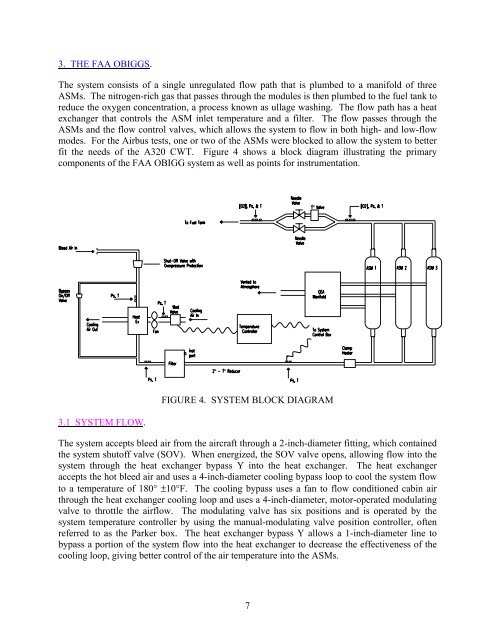
The system c<strong>on</strong>sists <str<strong>on</strong>g>of</str<strong>on</strong>g> a single unregulated flow path that is plumbed to a manifold <str<strong>on</strong>g>of</str<strong>on</strong>g> three<br />
ASMs. The nitrogen-rich gas that passes through <str<strong>on</strong>g>the</str<strong>on</strong>g> modules is <str<strong>on</strong>g>the</str<strong>on</strong>g>n plumbed to <str<strong>on</strong>g>the</str<strong>on</strong>g> fuel tank to<br />
reduce <str<strong>on</strong>g>the</str<strong>on</strong>g> oxygen c<strong>on</strong>centrati<strong>on</strong>, a process known as ullage washing. The flow path has a heat<br />
exchanger that c<strong>on</strong>trols <str<strong>on</strong>g>the</str<strong>on</strong>g> ASM inlet temperature and a filter. The flow passes through <str<strong>on</strong>g>the</str<strong>on</strong>g><br />
ASMs and <str<strong>on</strong>g>the</str<strong>on</strong>g> flow c<strong>on</strong>trol valves, which allows <str<strong>on</strong>g>the</str<strong>on</strong>g> system to flow in both high- and low-flow<br />
modes. For <str<strong>on</strong>g>the</str<strong>on</strong>g> Airbus tests, <strong>on</strong>e or two <str<strong>on</strong>g>of</str<strong>on</strong>g> <str<strong>on</strong>g>the</str<strong>on</strong>g> ASMs were blocked to allow <str<strong>on</strong>g>the</str<strong>on</strong>g> system to better<br />
fit <str<strong>on</strong>g>the</str<strong>on</strong>g> needs <str<strong>on</strong>g>of</str<strong>on</strong>g> <str<strong>on</strong>g>the</str<strong>on</strong>g> A320 CWT. Figure 4 shows a block diagram illustrating <str<strong>on</strong>g>the</str<strong>on</strong>g> primary<br />
comp<strong>on</strong>ents <str<strong>on</strong>g>of</str<strong>on</strong>g> <str<strong>on</strong>g>the</str<strong>on</strong>g> <str<strong>on</strong>g>FAA</str<strong>on</strong>g> OBIGG system as well as points for instrumentati<strong>on</strong>.<br />
3.1 SYSTEM FLOW.<br />
FIGURE 4. SYSTEM BLOCK DIAGRAM<br />
The system accepts bleed air from <str<strong>on</strong>g>the</str<strong>on</strong>g> aircraft through a 2-inch-diameter fitting, which c<strong>on</strong>tained<br />
<str<strong>on</strong>g>the</str<strong>on</strong>g> system shut<str<strong>on</strong>g>of</str<strong>on</strong>g>f valve (SOV). When energized, <str<strong>on</strong>g>the</str<strong>on</strong>g> SOV valve opens, allowing flow into <str<strong>on</strong>g>the</str<strong>on</strong>g><br />
system through <str<strong>on</strong>g>the</str<strong>on</strong>g> heat exchanger bypass Y into <str<strong>on</strong>g>the</str<strong>on</strong>g> heat exchanger. The heat exchanger<br />
accepts <str<strong>on</strong>g>the</str<strong>on</strong>g> hot bleed air and uses a 4-inch-diameter cooling bypass loop to cool <str<strong>on</strong>g>the</str<strong>on</strong>g> system flow<br />
to a temperature <str<strong>on</strong>g>of</str<strong>on</strong>g> 180° ±10°F. The cooling bypass uses a fan to flow c<strong>on</strong>diti<strong>on</strong>ed cabin air<br />
through <str<strong>on</strong>g>the</str<strong>on</strong>g> heat exchanger cooling loop and uses a 4-inch-diameter, motor-operated modulating<br />
valve to throttle <str<strong>on</strong>g>the</str<strong>on</strong>g> airflow. The modulating valve has six positi<strong>on</strong>s and is operated by <str<strong>on</strong>g>the</str<strong>on</strong>g><br />
system temperature c<strong>on</strong>troller by using <str<strong>on</strong>g>the</str<strong>on</strong>g> manual-modulating valve positi<strong>on</strong> c<strong>on</strong>troller, <str<strong>on</strong>g>of</str<strong>on</strong>g>ten<br />
referred to as <str<strong>on</strong>g>the</str<strong>on</strong>g> Parker box. The heat exchanger bypass Y allows a 1-inch-diameter line to<br />
bypass a porti<strong>on</strong> <str<strong>on</strong>g>of</str<strong>on</strong>g> <str<strong>on</strong>g>the</str<strong>on</strong>g> system flow into <str<strong>on</strong>g>the</str<strong>on</strong>g> heat exchanger to decrease <str<strong>on</strong>g>the</str<strong>on</strong>g> effectiveness <str<strong>on</strong>g>of</str<strong>on</strong>g> <str<strong>on</strong>g>the</str<strong>on</strong>g><br />
cooling loop, giving better c<strong>on</strong>trol <str<strong>on</strong>g>of</str<strong>on</strong>g> <str<strong>on</strong>g>the</str<strong>on</strong>g> air temperature into <str<strong>on</strong>g>the</str<strong>on</strong>g> ASMs.<br />
7