High-Current Bus-Powered Devices - FTDI
High-Current Bus-Powered Devices - FTDI
High-Current Bus-Powered Devices - FTDI

Create successful ePaper yourself
Turn your PDF publications into a flip-book with our unique Google optimized e-Paper software.
VCC5<br />
GND<br />
R1 - 100 K<br />
- LOAD ON<br />
FT8U232 / FT8U245<br />
<strong>High</strong>-<strong>Current</strong> <strong>Bus</strong>-<strong>Powered</strong> <strong>Devices</strong><br />
Q1<br />
R2 - 1 K<br />
TO LOAD<br />
Application Note AN232-10<br />
There are several points to consider when designing a high current, bus powered device<br />
with the FT8U232 or FT8U245 chips:<br />
1. The high power logic can only be switched on if the device is configured by the system.<br />
The power to the extra logic must be controlled to ensure the chip is powered off when the device<br />
is first plugged in. If you are plugged into a bus-powered hub and require more than 100mA, then<br />
you will not be configured. In addition, it is advisable to try to prevent sudden changes in power<br />
requirements. These can cause the voltage rail to drop down to 3 volts, although momentarily, and<br />
cannot be smoothed by capacitance alone.<br />
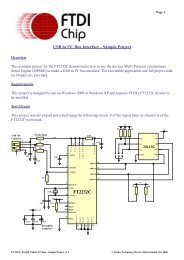
The following circuit performs two functions; It allows the power to the load to be switched off and<br />
on, and it provides a ‘slow start’ feature to prevent glitches on VCC. For Q1 a BCP69 - SOT223, or<br />
a ZTX718 - E line, or similar can be used.<br />
C1 - 100 nF<br />
C2 - 47pF<br />
<strong>High</strong> <strong>Current</strong> <strong>Bus</strong> <strong>Powered</strong> Designs (c) Future Technology <strong>Devices</strong> Intl. Ltd. 2002
Application Note AN232-10<br />
The following oscilloscope trace shows the circuit driving a 25 Ohm / 5uF load.<br />
<strong>High</strong> <strong>Current</strong> <strong>Bus</strong> <strong>Powered</strong> Designs (c) Future Technology <strong>Devices</strong> Intl. Ltd. 2002
Application Note AN232-10<br />
2. The high power part of the circuit must be powered down during suspend or reset.<br />
For the FT8U232 device the -LOAD ON signal should be controlled by a CMOS 2 input NAND<br />
gate. The inputs used should be RCCLK (to indicate suspend) and USBEN (to indicate the<br />
configuration). The USBEN signal should be pulled down using a 100K resistor as it will tri-state<br />
during reset. If the Base of the transistor is being driven by CMOS logic, then it is not necessary to<br />
connect a resistor between the Base and Emitter. The high drive of the CMOS gate will ensure that<br />
the transistor is turned off<br />
USB VCC5<br />
100 K<br />
A<br />
1K<br />
To Load<br />
0.1 uF<br />
47 pF<br />
(a) Circuit for use with the FT8U232AM to control the power to a high power load<br />
<strong>High</strong> <strong>Current</strong> <strong>Bus</strong> <strong>Powered</strong> Designs (c) Future Technology <strong>Devices</strong> Intl. Ltd. 2002
Application Note AN232-10<br />
In the case of the FT8U245 device the design needs to be a bit more complex. In order to indicate<br />
that the device has been configured a latch arrangement should be used. If RESET# is used to<br />
pull up RCCLK instead of VCC, then RCCLK can be used to set the latch output high (OFF - The<br />
output of the NAND gate is driving -Load On). If RXFULL# goes low then this can be used to reset<br />
the latch output to low, and thus turn the power on. In this manner, the device is powered up by<br />
writing a byte to it.<br />
USB VCC5<br />
RCCLK<br />
RXFULL#<br />
A<br />
B<br />
To Load<br />
<strong>High</strong> <strong>Current</strong> <strong>Bus</strong> <strong>Powered</strong> Designs (c) Future Technology <strong>Devices</strong> Intl. Ltd. 2002<br />
1K<br />
GND<br />
0.1 uF<br />
47 pF<br />
(b) Circuit for use with the FT8U245AM to control the power to a high power load
3. Telling the system that you need more than 100mA.<br />
Application Note AN232-10<br />
The system needs to be told that more than 100mA of current is required. This is done within the<br />
EEPROM using the application FTD2XXST.exe. A field is available which specifies the maximum<br />
number of milliamps required. An example of this is shown on the screenshots below.<br />
Start the application and select ‘‘File / New’’. You should have an empty screen like the following:<br />
<strong>High</strong> <strong>Current</strong> <strong>Bus</strong> <strong>Powered</strong> Designs (c) Future Technology <strong>Devices</strong> Intl. Ltd. 2002
Application Note AN232-10<br />
Next fill in the required fields. Use the TAB key to move between fields. You will notice that when<br />
you have filled in all the fields and gone back to the beginning, that the hand with pointing finger is<br />
highlighted in the toolbar. See the sample screenshot below:<br />
<strong>High</strong> <strong>Current</strong> <strong>Bus</strong> <strong>Powered</strong> Designs (c) Future Technology <strong>Devices</strong> Intl. Ltd. 2002
Application Note AN232-10<br />
Next click on the hand in the<br />
toolbar and select the appropriate<br />
for your design. You should not<br />
make it ‘’Self <strong>Powered</strong>’’ (don’t<br />
check the box) and put an<br />
appropriate amount into the ‘‘Max<br />
Power (mA)’’ field. The maximum<br />
amount allowed here is 500mA,<br />
but don’t specify this value. Use<br />
490mA instead<br />
Click ‘OK’ to return to the main screen. A save option will now be highlighted on the toolbar,<br />
immediately to the left of the pointing hand.<br />
<strong>High</strong> <strong>Current</strong> <strong>Bus</strong> <strong>Powered</strong> Designs (c) Future Technology <strong>Devices</strong> Intl. Ltd. 2002
Application Note AN232-10<br />
Clicking here will save the information for you, and will then allow you advance to program the<br />
device. More options will be available on the toolbar as illustrated in the screenshot below:<br />
<strong>High</strong> <strong>Current</strong> <strong>Bus</strong> <strong>Powered</strong> Designs (c) Future Technology <strong>Devices</strong> Intl. Ltd. 2002
Application Note AN232-10<br />
Click the button with hand and pen icon. The following screen should be shown after you have<br />
successfully programmed a device. (Note: the serial number will be different.)<br />
The device is now ready to use.<br />
<strong>High</strong> <strong>Current</strong> <strong>Bus</strong> <strong>Powered</strong> Designs (c) Future Technology <strong>Devices</strong> Intl. Ltd. 2002