Groove Welds Unit 16 - Goodheart-Willcox
Groove Welds Unit 16 - Goodheart-Willcox
Groove Welds Unit 16 - Goodheart-Willcox

Create successful ePaper yourself
Turn your PDF publications into a flip-book with our unique Google optimized e-Paper software.
This sample chapter is for review purposes only. Copyright © The <strong>Goodheart</strong>-<strong>Willcox</strong> Co., Inc. All rights reserved.<br />
1<br />
TO<br />
3<br />
<strong>16</strong> <strong>16</strong><br />
ANGLE X<br />
45° MIN<br />
20° MIN<br />
12° MIN<br />
X<br />
R 1 4 MIN<br />
3<br />
<strong>16</strong> MAX.<br />
POSITION<br />
ALL<br />
F, V, O<br />
F<br />
DETAIL E<br />
(EXCEPT FROM DWG B2345,<br />
"GROOVE WELD STANDARDS")<br />
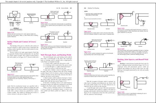
Figure <strong>16</strong>-<strong>16</strong>.<br />
<strong>Groove</strong> radii and root faces of U- and J-groove welds are<br />
shown by cross section, detail, or other means with a welding<br />
symbol reference.<br />
Surface Finish and Contour of <strong>Groove</strong><br />
<strong>Welds</strong><br />
The buildup of the groove weld above the surface of<br />
the base material is called reinforcement. Sometimes the<br />
welding symbol specifies that the reinforcement be minimized<br />
or removed.<br />
<strong>Groove</strong> welds to be made approximately flush (but<br />
not generally finished flush mechanically) are specified<br />
by a flush contour symbol. This symbol is placed above<br />
the weld symbol, as in Figure <strong>16</strong>-17. <strong>Groove</strong> welds to be<br />
Weld deposited<br />
flush with<br />
base metal<br />
SEE DWG B2345<br />
DETAIL E<br />
Symbol<br />
Desired weld Symbol<br />
Figure <strong>16</strong>-17.<br />
A flush contour symbol is placed above the weld symbol when<br />
the groove weld is to be made approximately flush<br />
and without the use of grinding, chipping, hammering, or<br />
machining.<br />
made flush by mechanical means are specified with a<br />
flush contour symbol and the method of making the weld<br />
flush, Figure <strong>16</strong>-18. <strong>Groove</strong> welds to be finished mechanically<br />
with a convex contour are specified by a convex<br />
contour symbol. The method of finishing the weld to a<br />
convex contour is also given, Figure <strong>16</strong>-19.<br />
Weld made flush<br />
with base metal<br />
by grinding<br />
Desired weld Symbol<br />
Figure <strong>16</strong>-18.<br />
<strong>Groove</strong> welds to be made flush mechanically are specified by<br />
a flush contour symbol and by the method to use to make the<br />
weld flush.<br />
Finished to smooth<br />
convex contour<br />
by machining<br />
<strong>Unit</strong> <strong>16</strong> <strong>Groove</strong> <strong>Welds</strong> 201<br />
Desired weld Symbol<br />
Figure <strong>16</strong>-19.<br />
When groove welds are to be finished mechanically to a flush<br />
contour, they are specified by a convex contour symbol and<br />
the method of finishing.<br />
Melt-Through, Back, and Backing <strong>Welds</strong><br />
The melt-through, back, and backing weld symbols<br />
show that a melt-through to the other side, bead-type<br />
back, or backing weld is needed with a single-groove<br />
weld. Points to remember include:<br />
❍ A back weld is made after the groove weld.<br />
❍ A backing weld is made before the groove weld.<br />
❍ A melt-through is a visible reinforcement produced<br />
in a groove weld from one side.<br />
A note states whether a back or backing weld is to<br />
be made. This note is placed in the tail of the welding<br />
symbol, Figure <strong>16</strong>-20. As shown, a back or backing weld<br />
symbol is located on the side of the reference line that is<br />
opposite the groove weld symbol.<br />
A flush contour symbol, added to the back or backing<br />
weld symbol, indicates the weld should be approximately<br />
flush with the base metal, Figure <strong>16</strong>-21.<br />
If the back or backing weld is to be made flush by<br />
mechanical means, the method of making the weld flush<br />
is added to the flush contour symbol, Figure <strong>16</strong>-22.<br />
When a back or backing weld is to be finished to<br />
a convex contour by mechanical means, a convex contour<br />
symbol and finish symbol are added to the weld<br />
symbol.<br />
G<br />
M<br />
M<br />
202 Welding Print Reading<br />
NOTE-<br />
1. GROOVE WELD MADE BEFORE<br />
WELDING OTHER SIDE.<br />
2.<br />
(ABOVE FOUND ELSEWHERE ON PRINT)<br />
Back weld<br />
Desired welds<br />
Backing weld machined<br />
flush with base metal<br />
Weld deposited flush<br />
with base metal<br />
Symbol<br />
Desired welds Symbol<br />
Desired welds Symbol<br />
Figure <strong>16</strong>-22.<br />
A symbol added above the flush contour symbol identifies the<br />
mechanical method used to finish the weld flush.<br />
With the exception of height, which is optional, no<br />
other back or backing weld dimensions are shown with<br />
the weld symbol, Figure <strong>16</strong>-23. If other dimensions are<br />
required, they are shown on the drawing.<br />
A melt-through weld assures full joint penetration.<br />
The melt-through weld symbol is similar to the back or<br />
backing weld symbol with the bead filled in as shown in<br />
Figure <strong>16</strong>-24. A dimension to the left of the symbol specifies<br />
the amount of melt-through.<br />
M<br />
NOTE 1<br />
Figure <strong>16</strong>-20.<br />
Specifications for a back weld. A note in the tail of the reference<br />
line indicates whether to make a back or backing weld.<br />
NOTE 1<br />
Figure <strong>16</strong>-21.<br />
A flush contour symbol indicates the weld is to be finished<br />
approximately flush with the base metal.<br />
NOTE 2<br />
1<br />
<strong>16</strong><br />
1<br />
<strong>16</strong><br />
Desired weld Symbol<br />
Figure <strong>16</strong>-23.<br />
Only the back or backing weld height dimension is shown on<br />
the welding symbol. If other dimensions are needed, they are<br />
given elsewhere on the print.<br />
1<br />
8<br />
Desired weld Symbol<br />
Figure <strong>16</strong>-24.<br />
The melt-through weld symbol resembles the back or backing<br />
weld symbol, but the bead is filled in. The height of root reinforcement<br />
may appear as a dimension specified to the left of<br />
the melt-through symbol. (American Welding Society)<br />
Backing, Joint Spacers, and Runoff Weld<br />
Tabs<br />
Backing is material placed against the back side of a<br />
joint to withstand molten weld metal, Figure <strong>16</strong>-25. It is<br />
employed when full penetration groove welds are<br />
required and welding can only be done from one side.<br />
Backing is thoroughly penetrated by the weld and usually<br />
left in place.<br />
Backing<br />
Desired weld Symbol<br />
Figure <strong>16</strong>-25.<br />
Backing used in a joint. A specification indicating its use is<br />
shown in the tail of the reference line.<br />
1<br />
8<br />
B-3