Installation OB60 & OB90 - Fisher & Paykel
Installation OB60 & OB90 - Fisher & Paykel
Installation OB60 & OB90 - Fisher & Paykel

You also want an ePaper? Increase the reach of your titles
YUMPU automatically turns print PDFs into web optimized ePapers that Google loves.
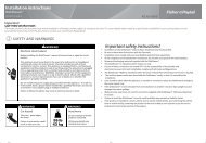
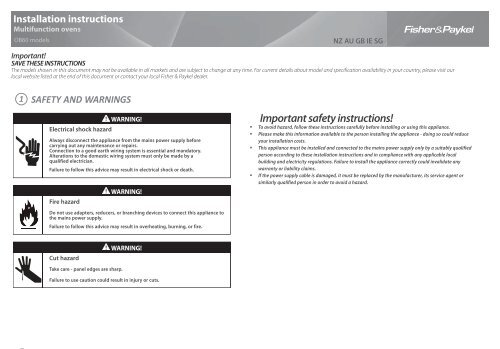
<strong>Installation</strong> instructions<br />
Multifunction ovens<br />
<strong>OB60</strong> models NZ AU GB IE SG<br />
Important!<br />
SAVE THESE INSTRUCTIONS<br />
The models shown in this document may not be available in all markets and are subject to change at any time. For current details about model and specification availability in your country, please visit our<br />
local website listed at the end of this document or contact your local <strong>Fisher</strong> & <strong>Paykel</strong> dealer.<br />
1<br />
SAFETY AND WARNINGS<br />
WARNING!<br />
Electrical shock hazard<br />
Always disconnect the appliance from the mains power supply before<br />
carrying out any maintenance or repairs.<br />
Connection to a good earth wiring system is essential and mandatory.<br />
Alterations to the domestic wiring system must only be made by a<br />
qualified electrician.<br />
Failure to follow this advice may result in electrical shock or death.<br />
Fire hazard<br />
WARNING!<br />
Do not use adapters, reducers, or branching devices to connect this appliance to<br />
the mains power supply.<br />
Failure to follow this advice may result in overheating, burning, or fire.<br />
Cut hazard<br />
Take care - panel edges are sharp.<br />
WARNING!<br />
Failure to use caution could result in injury or cuts.<br />
Important safety instructions!<br />
To avoid hazard, follow these instructions carefully before installing or using this appliance.<br />
Please make this information available to the person installing the appliance - doing so could reduce<br />
your installation costs.<br />
This appliance must be installed and connected to the mains power supply only by a suitably qualified<br />
person according to these installation instructions and in compliance with any applicable local<br />
building and electricity regulations. Failure to install the appliance correctly could invalidate any<br />
warranty or liability claims.<br />
If the power supply cable is damaged, it must be replaced by the manufacturer, its service agent or<br />
similarly qualified person in order to avoid a hazard.
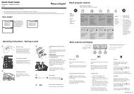
2 PRODUCT & CABINETRY DIMENSIONS<br />
Product dimensions (mm) <strong>OB60</strong>S<br />
A overall height* of product 597 450**<br />
B overall width of product 595 595<br />
C overall depth of product (excluding handle and knobs) 567 556<br />
D height of chassis 582 436<br />
E width of chassis 556 536<br />
F depth of chassis 545 534<br />
G<br />
depth of oven frame and control panel<br />
(=distance between front of chassis and front of oven door, excl. knobs)<br />
22 22<br />
H<br />
<strong>OB60</strong>S & <strong>OB60</strong>N MODELS<br />
<strong>Installation</strong> diagrams for<br />
illustration purposes only<br />
H<br />
A<br />
C E<br />
B<br />
depth of oven door when fully open (measured from front of<br />
control panel)<br />
G<br />
<strong>OB60</strong>N<br />
435 289<br />
I minimum inside width of cavity 560 560<br />
I I overall width of cavity 600 600<br />
J inside height of cavity 585 440**<br />
J I overall height of cavity 600 455**<br />
K minimum inside depth of cavity 550 550<br />
L flush fitting cabinetry clearance 22 22<br />
Note: If installing a cooktop above the oven, ensure adequate clearance is provided for the cooktop as per the cooktop<br />
manufacturer’s instructions.<br />
*All height measurements include mounted feet.<br />
** If fi tting the lower trim extension kit, the overall height of product (A) increases by 25 mm (to 475 mm).<br />
The height of the cavity (J and Ji) therefore needs to be increased by 25 mm also (to 465 mm and 480 mm respectively).<br />
F<br />
D<br />
L<br />
K<br />
I<br />
I<br />
I<br />
L<br />
J<br />
J I<br />
16-20 mm<br />
2.5 mm<br />
Product dimensions (mm) <strong>OB60</strong>B<br />
A overall height* of product 888 1077<br />
B overall width of product 595 595<br />
C overall depth of product (excluding handle and knobs) 567 567<br />
D height of chassis 874 1057<br />
E width of chassis 556 556<br />
F depth of chassis 545 545<br />
G<br />
depth of oven frame and control panel<br />
(=distance between front of chassis and front of oven door, excl. knobs)<br />
22 22<br />
H<br />
H I<br />
<strong>OB60</strong>B & <strong>OB60</strong>D MODELS<br />
H<br />
H I<br />
C<br />
A<br />
depth of upper oven door when fully open<br />
(measured from front of control panel)<br />
depth of lower oven door when fully open<br />
(measured from front of control panel)<br />
<strong>OB60</strong>D<br />
261 435<br />
435 450<br />
I minimum inside width of cavity 560 560<br />
I I overall width of cavity 600 600<br />
J inside height of cavity 877 1065<br />
J I overall height of cavity 893 1082<br />
K minimum inside depth of cavity 550 550<br />
L flush fitting cabinetry clearance 22 22<br />
*All height measurements include mounted feet.<br />
B<br />
G<br />
E<br />
F<br />
D<br />
L<br />
I<br />
I<br />
I<br />
K<br />
L<br />
J<br />
J I<br />
16-20 mm<br />
2.5 mm
3<br />
4<br />
PRIOR TO INSTALLATION<br />
Before you install the oven, make sure that<br />
the benchtop and oven cavity are square and level, and are the required dimensions<br />
the installation will comply with all clearance requirements and applicable standards and regulations<br />
a suitable isolating switch providing full disconnection from the mains power supply is incorporated in<br />
the permanent wiring, mounted and positioned to comply with the local wiring rules and regulations.<br />
The isolating switch must be of an approved type and provide a 3 mm air gap contact separation<br />
in all poles (or in all active [phase] conductors if the local wiring rules allow for this variation of the<br />
requirements)<br />
the isolating switch will be easily accessible to the customer with the oven installed<br />
there is at least 1.5 m (and not more than 2 m) free length of power supply cable within the cavity for<br />
ease of installation and servicing<br />
the oven connection socket (if fitted) is outside the cavity if the oven is flush to the rear wall<br />
the oven will rest on a surface that can support its weight<br />
the height from the floor suits the customer<br />
you consult local building authorities and by-laws if in doubt regarding installation.<br />
Important!<br />
Some environmental factors and cooking habits can cause condensation in and around the oven during use.<br />
To protect surrounding cabinetry from possible damage caused by frequent or excessive condensation, we<br />
recommend moisture-proofing the oven cavity.<br />
UNPACKING THE OVEN<br />
Important!<br />
Do not lift the oven by the door handle.<br />
Remove all packaging and dispose of it responsibly. Recycle items that you can.<br />
Place the unpacked oven onto wooden blocks or similar supports to prevent damaging the lower trim.<br />
You may remove the feet, but ensure the oven does not sit on the lower trim<br />
Important!<br />
The lower trim ensures correct air circulation and allows the door to open and close without obstruction. The<br />
manufacturer does not accept any responsibility for damage resulting from incorrect installation.<br />
AIR FLOW<br />
OVEN DOOR<br />
LOWER TRIM<br />
LOWER TRIM<br />
FEET<br />
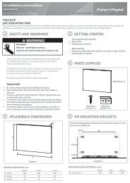
5 ELECTRICAL CONNECTION<br />
Important!<br />
This oven must be connected to the mains power supply only by a suitably qualified person.<br />
This oven must be earthed.<br />
Before connecting the oven to the mains power supply, check that<br />
the domestic wiring system is suitable for the power drawn by the oven<br />
(as specified on the rating plate)<br />
the voltage corresponds to the value given on the rating plate.<br />
<strong>OB60</strong>S & <strong>OB60</strong>N MODELS<br />
Model code Power Voltage<br />
<strong>OB60</strong>SLC... 2350-2550 W 230 - 240 V~<br />
<strong>OB60</strong>SLM... 3070 W 220-240 V~<br />
<strong>OB60</strong>SCE... 3070 W 220-240 V~<br />
<strong>OB60</strong>SCM... 3070 W 220-240 V~<br />
<strong>OB60</strong>SCT... 3600 W 230 V~<br />
<strong>OB60</strong>SDT... 3600 W 230 V~<br />
<strong>OB60</strong>S9D... 3400 W 220-240 V~<br />
<strong>OB60</strong>SV... 3070 W 220-240 V~<br />
<strong>OB60</strong>NL... 2050 W 220-240 V~<br />
<strong>OB60</strong>NC... 2800 W 220-240 V~<br />
<strong>OB60</strong>ND... 2800 W 220-240 V~<br />
<strong>OB60</strong>B & <strong>OB60</strong>D MODELS<br />
Model code Power Voltage<br />
<strong>OB60</strong>BC... 5800 W 220 - 240 V~<br />
<strong>OB60</strong>BD... 5800 W 220 - 240 V~<br />
<strong>OB60</strong>B77C... 5850 W 220 - 240 V~<br />
<strong>OB60</strong>B77D... 5850 W 220 - 240 V~<br />
<strong>OB60</strong>DD... 6120 W 220 - 240 V~<br />
L1 N(L<br />
2 )<br />
E<br />
L1 N(L<br />
2)<br />
E<br />
1<br />
1<br />
2<br />
Unscrew to<br />
remove cover<br />
plate<br />
2<br />
Brown (Live)<br />
Blue (Neutral)<br />
Unhook to open cover<br />
L<br />
Unscrew to open<br />
cable clamp<br />
N<br />
D<br />
Green & Yellow<br />
(Earth)<br />
Unscrew to remove<br />
cable clamp
6<br />
SECURING OVEN TO CABINETRY<br />
1 Position the oven in the prepared cavity.<br />
Important!<br />
Do not lift the oven by the door handle.<br />
2 Open the oven door fully.<br />
3 Use the supplied screws to secure the oven to the cabinetry.<br />
Important!<br />
Do not over-tighten the screws.<br />
Do not seal the oven into the cabinetry with silicone or glue. This makes future servicing difficult.<br />
<strong>Fisher</strong> & <strong>Paykel</strong> will not cover the costs of removing the oven, or of damage caused by this removal.<br />
2.5 mm<br />
7 FINAL CHECKLIST<br />
Make sure the oven is level and securely fitted to the cabinetry and the oven<br />
door opens and closes freely.<br />
Make sure all the internal packaging has been removed from the oven cavity.<br />
Make sure all oven vents and openings are clear and are free of any<br />
obstruction/damage.<br />
Check the lower trim is still undamaged - open the oven door slowly to its fully<br />
open position and check if there is adequate clearance between the bottom of<br />
the door and the lower trim. This is to ensure correct air circulation. Should the<br />
lower trim become damaged, straighten the trim and ensure the oven door<br />
opens fully without obstruction.<br />
Check that the power supply cable does not touch any metal parts that can<br />
become hot during use.<br />
Make sure that the isolating switch is easily accessible by the customer.<br />
Turn the power to the oven on. On some models, the display should light up<br />
and show 0:00.<br />
Advise the customer to follow the instructions in their user guide in section<br />
‘First use’.<br />
www.fi sherpaykel.co.nz www.fi sherpaykel.com.au www.fi sherpaykel.co.uk www.fi sherpaykel.ie www.fi sherpaykel.eu www.fi sherpaykel.com.sg F&P Italy Part No. 1103268-ß5 599790E NZ AU GB IE 03.12
<strong>Installation</strong> instructions<br />
IZONA CookSpace multifunction pyrolytic oven<br />
<strong>OB90</strong> models NZ AU GB IE<br />
Important!<br />
SAVE THESE INSTRUCTIONS<br />
The models shown in this document may not be available in all markets and are subject to change at any time. For current details about model and specification availability in your country, please visit our local<br />
website listed at the end of this document or contact your local <strong>Fisher</strong> & <strong>Paykel</strong> dealer.<br />
1<br />
SAFETY AND WARNINGS<br />
WARNING!<br />
Electrical hazard<br />
Always disconnect the oven from<br />
the mains electricity supply<br />
before carrying out any<br />
maintenance operations or<br />
repairs.<br />
Failure to do so may result in<br />
electrical shock or death.<br />
Cut hazard<br />
Take care - panel edges are sharp.<br />
WARNING!<br />
124 lb<br />
56 kg<br />
Failure to use caution could result in injury or cuts.<br />
WARNING!<br />
Very Heavy<br />
Do not attempt to lift this<br />
product unassisted.<br />
Lifting unassisted may<br />
cause serious injury.<br />
Important safety instructions!<br />
To avoid hazard, follow these instructions carefully before installing or using this product.<br />
Please make this information available to the person installing the product as it could reduce your<br />
installation costs.<br />
This oven is to be installed and connected to the electricity supply only by an authorised person.<br />
If the installation requires alterations to the domestic electrical system, call a qualified electrician. The<br />
electrician should also check that the power supply cable section is suitable for the electricity drawn by the<br />
oven.<br />
The oven must be earthed.<br />
Do not use adapters, reducers or branching devices to connect the oven to the mains electricity supply,<br />
as they can cause overheating and burning.<br />
<strong>Installation</strong> must comply with your local building and electricity regulations.<br />
Failure to install the oven correctly could invalidate any warranty or liability claims.<br />
Before you install the oven, please make sure that<br />
it will be lifted by two people.<br />
the oven will rest on a flat surface that can support its weight.<br />
the benchtop and oven cavity are square and level, and are the required dimensions.<br />
the height from the floor suits the customer.<br />
the oven door can open fully without obstruction.<br />
a suitable isolating switch providing full disconnection from the mains power supply (under overvoltag<br />
category III conditions) is incorporated in the permanent wiring, mounted and positioned to comply w<br />
the local wiring rules and regulations. The isolating switch must be of an approved type and provide a<br />
mm air gap contact separation in all poles (or in all active [phase] conductors if the local wiring rules a<br />
for this variation of the requirements).<br />
the electrician provides sufficient free length of power supply cable to reach from the bottom rear of t<br />
cavity to at least 1.5 metres in front of the bottom edge of the opening. The cable may enter the cavity<br />
from the side, top or bottom, but top entry must be at the rear of the cavity.<br />
When you install the oven<br />
Do not seal the oven into the cabinetry with silicone or glue. This makes future servicing difficult. Fishe<br />
<strong>Paykel</strong> will not cover the costs of removing the oven, or of damage caused by this removal.<br />
Use the supplied screws to secure the oven to the cabinetry. Do not over-tighten the screws.<br />
Make sure that the power supply cable will not touch any hot metal parts.<br />
Make sure that the isolating switch will be easily accessible by the customer.<br />
Do not stand on the door, or place heavy objects on it.<br />
Do not lift the oven by the door handle.<br />
Take extra care not to damage the lower trim of the oven. We suggest you place the unpacked oven on<br />
wooden blocks or similiar supports.<br />
When handling the oven, take care not to damage the door sensor lever<br />
(near the top right corner of the oven seal).<br />
Use easy-to-clean finishes for the wall surfaces surrounding the oven, so that cooking fume staining<br />
resulting from using the oven is easy to remove.
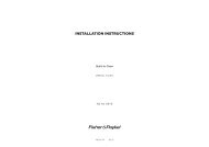
2 PRODUCT DIMENSIONS<br />
<strong>Installation</strong> diagrams for illustration purposes only<br />
H<br />
A<br />
Product dimensions (mm)<br />
C<br />
B<br />
E<br />
G<br />
F<br />
<strong>OB90</strong><br />
models<br />
A overall height of product (including upper and lower vents) 478<br />
B overall width of product 895<br />
C overall depth of product (without handle and dials) 566<br />
D height of chassis at the rear 462<br />
D I overall height of chassis 467<br />
E maximum width of chassis 853<br />
F depth of chassis 544<br />
G depth of oven frame and control panel (excl. dials) 22<br />
H depth of oven door (open) (measured from front of control panel) 415<br />
Note: If installing a cooktop above the oven, ensure adequate clearance is provided for the cooktop as per the<br />
cooktop manufacturer’s instructions.<br />
D<br />
D I<br />
G<br />
16-20 mm<br />
2.5 mm<br />
Ensure the cavity is completely sealed with no gaps<br />
3 CABINETRY DIMENSIONS<br />
Cabinetry dimensions (mm)<br />
A<br />
B I<br />
B<br />
C<br />
<strong>OB90</strong><br />
models<br />
A minimum inside depth of cavity 550<br />
B minimum inside width of cavity 860<br />
B I overall width of cabinetry 900<br />
C height of cavity 480
e<br />
ith<br />
3<br />
low<br />
e<br />
r &<br />
to<br />
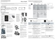
4 UNPACK THE OVEN 5 REMOVE THE DOOR<br />
6 ELECTRICAL CONNECTION 7 HARD WIRING THE OVEN<br />
Rating plate<br />
<strong>OB90</strong> - NZ AU GB IE<br />
220-240 V 4400 W (19.1 A)<br />
<strong>OB90</strong> - IT<br />
220-240 V 3500 W (15.2 A)<br />
Connecting the oven to the<br />
mains power supply<br />
Important!<br />
This oven must be connected to the<br />
mains power supply only by a suitably<br />
qualified person.<br />
This oven must be earthed.<br />
Before connecting the oven to the<br />
mains power supply, check that<br />
the domestic wiring system is suitable<br />
for the power drawn by the oven<br />
(as specified on the rating plate)<br />
the voltage corresponds to the value<br />
given on the rating plate.<br />
We recommend that the outlet for the power supply cable is located in the right rear corner of<br />
the cabinet cavity. This allows the power supply cable to sit inside the right rear of the oven and<br />
prevents it being jammed between the cabinet wall and the rear of the oven.<br />
1<br />
1 2 3<br />
4<br />
Unhook to<br />
open cover<br />
L1 E N(L<br />
2)<br />
2<br />
Unhook to open<br />
cable clamp
8 SECURE THE OVEN TO THE CABINETRY<br />
9<br />
Take care not to<br />
damage the upper<br />
trim of the oven or<br />
the door sensor lever<br />
2<br />
1<br />
1 Lift from both sides placing<br />
hands under the oven chassis<br />
2 Push oven in, ensuring you’re<br />
not pushing on the vents or<br />
control panel<br />
3 Secure oven to cabinetry using<br />
supplied scews<br />
10 FINAL CHECKLIST<br />
11<br />
Make sure the appliance is level and securely fitted to the cabinetry and the<br />
oven door opens and closes freely.<br />
Make sure all the internal packaging has been removed from the oven cavity.<br />
Make sure all oven vents and openings are clear and are free of any<br />
obstruction/damage.<br />
Important!<br />
Failure to make sure all oven vents are unobstructed may result in poor product performance.<br />
Make sure that the isolating switch is accessible by the customer.<br />
Turn the power to the oven on. The display should light up and show 0:00.<br />
Turn the oven function dial to ‘Bake’. Air should blow out of the vent at the top<br />
of the oven. Inside the oven cavity, both oven lights should come on. After<br />
five minutes, open the oven door: the air inside should feel warm.<br />
Turn the oven function dial back to OFF.<br />
3<br />
x4<br />
REFIT THE DOOR<br />
1 2 3<br />
TROUBLESHOOTING<br />
4<br />
If the appliance is not functioning correctly after installation, check the<br />
following:<br />
Check that the circuit breaker has not tripped or the fuse blown.<br />
Make sure that the electrical connections have been correctly made.<br />
Make sure that power is being supplied to the oven.<br />
Make sure the voltage is correct across all phases.<br />
If a problem occurs, consult the Troubleshooting section of the User Guide.<br />
If after checking these points you still need assistance or parts, please refer to<br />
the Service & Warranty book for warranty details and your nearest Authorised<br />
Repairer, or contact us through our local website, listed below.<br />
www.fi sherpaykel.co.nz www.fi sherpaykel.com.au www.fi sherpaykel.co.uk www.fi sherpaykel.ie www.fi sherpaykel.eu F&P Italy Part No. 1103268-ß5 599790E NZ AU GB IE 03.12