WORK Microwave's Handheld Satcom Test Source

Create successful ePaper yourself
Turn your PDF publications into a flip-book with our unique Google optimized e-Paper software.
TEST REPORT<br />
<strong>Test</strong> Signal Generator<br />
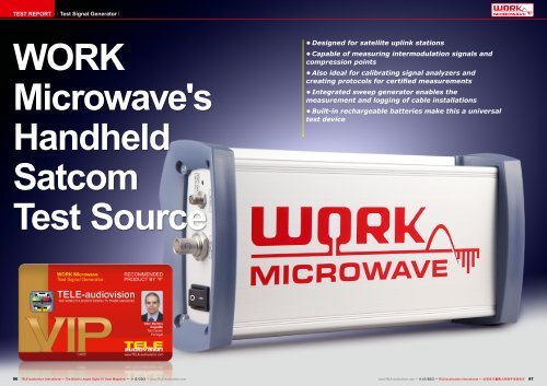
<strong>WORK</strong><br />
<strong>Microwave's</strong><br />
<strong>Handheld</strong><br />
• Designed for satellite uplink stations<br />
• Capable of measuring intermodulation signals and<br />
compression points<br />
• Also ideal for calibrating signal analyzers and<br />
creating protocols for certified measurements<br />
• Integrated sweep generator enables the<br />
measurement and logging of cable installations<br />
• Built-in rechargeable batteries make this a universal<br />
test device<br />
<strong>Satcom</strong><br />
<strong>Test</strong> <strong>Source</strong><br />
96 TELE-audiovision International — The World‘s Largest Digital TV Trade Magazine — 11-12/2013 — www.TELE-audiovision.com<br />
www.TELE-audiovision.com — 11-12/2013 — TELE-audiovision International — 全 球 发 行 量 最 大 的 数 字 电 视 杂 志 97
TEST REPORT<br />
<strong>Test</strong> Signal Generator<br />
The Reference<br />
Determines the Quality<br />
In order to be able to measure<br />
complex analog systems,<br />
calibrate test equipment<br />
or test high-frequency<br />
converters, you need to have<br />
a test signal generator. This<br />
device generates a signal<br />
at a specific frequency and<br />
power level where its precision<br />
is extremely critical<br />
since it is to be used as a<br />
reference signal.<br />
<strong>WORK</strong> Microwave offers<br />
exactly this kind of test signal<br />
generator; it can produce<br />
signals from 50-180 MHz and<br />
also from 950-2150 MHz.<br />
The <strong>Handheld</strong> <strong>Satcom</strong> <strong>Test</strong><br />
<strong>Source</strong> is shipped in a suitable<br />
protective package in<br />
which you‘ll find a red aluminum<br />
case, two USB cables<br />
(A-B) and a power cable.<br />
When you open up the<br />
red aluminum case you‘ll<br />
find in its padding the signal<br />
generator, the power supply,<br />
a USB stick, the user<br />
manual and a certificate of<br />
conformance certifying that<br />
the <strong>Handheld</strong> <strong>Satcom</strong> <strong>Test</strong><br />
<strong>Source</strong> complies with the<br />
listed parameters. It is even<br />
noted on the certificate that<br />
any documentation that was<br />
used in the manufacture of<br />
this signal generator can<br />
be made available upon request.<br />
This kind of documentation<br />
results in traceability;<br />
all measured values can be<br />
traced as far back as the<br />
manufacturer <strong>WORK</strong> Microwave<br />
thereby precluding any<br />
discussions on any measurement<br />
results.<br />
Page 15 of the user manual<br />
explains all of the functions<br />
of the test signal generator<br />
in a detailed yet easy-tounderstand<br />
format. The installation<br />
of the unit is quite<br />
simple. You only need to run<br />
the executable file from the<br />
USB storage device. An actual<br />
installation is not necessary.<br />
Naturally, you can<br />
also copy the program to the<br />
hard drive.<br />
The manufacturer was also<br />
thoughtful enough to include<br />
a copy of the user manual in<br />
the USB storage device. Installing<br />
drivers is not necessary<br />
since Windows XP, Windows<br />
Vista and Windows 7<br />
will recognize the instrument<br />
as an HID (Human Interface<br />
Device) and automatically<br />
incorporate it into the operating<br />
system.<br />
The <strong>Handheld</strong> <strong>Satcom</strong> <strong>Test</strong><br />
<strong>Source</strong> has an elongated<br />
housing fabricated out of<br />
aluminum. There‘s no doubt<br />
that this is a robust test instrument<br />
that is further protected<br />
on the front and back<br />
by hardened plastic. On the<br />
front panel you‘ll find the<br />
11-12/2013<br />
<strong>WORK</strong> Microwave<br />
<strong>Handheld</strong> <strong>Satcom</strong> <strong>Test</strong> <strong>Source</strong><br />
Allows for precise and certified<br />
high-frequency measurements<br />
www.TELE-audiovision.com/13/11/work-microwave<br />
■<br />
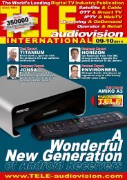
TELE-audiovision Editor Vitor<br />
in action. It's not nearly as<br />
difficult as it looks.<br />
98 TELE-audiovision International — The World‘s Largest Digital TV Trade Magazine — 11-12/2013 — www.TELE-audiovision.com<br />
www.TELE-audiovision.com — 11-12/2013 — TELE-audiovision International — 全 球 发 行 量 最 大 的 数 字 电 视 杂 志 99
1<br />
power supply input (12V-<br />
24V), two USB type B inputs<br />
and three status LEDs. The<br />
first LED indicates the instruments<br />
operational status<br />
(OK or error), the second<br />
LED shows the charging status<br />
of the rechargeable battery<br />
and the third one shows<br />
the system status.<br />
The two USB inputs have<br />
different functions. USB1<br />
serves as an additional<br />
source of power and also<br />
provides for the data communication<br />
with the PC.<br />
USB2 is exclusively used to<br />
provide power to the unit if<br />
for some reason the external<br />
power supply can‘t be used.<br />
The <strong>Handheld</strong> <strong>Satcom</strong> <strong>Test</strong><br />
<strong>Source</strong> runs from an internal<br />
rechargeable battery that<br />
lets you use it without having<br />
to keep it connected to<br />
a power source. This is not<br />
surprising considering this is<br />
a portable signal generator.<br />
It‘s also interesting that this<br />
instrument can be operated<br />
from a PC or laptop via the<br />
USB ports and since a single<br />
USB port cannot provide<br />
enough power, the <strong>Handheld</strong><br />
<strong>Satcom</strong> <strong>Test</strong> <strong>Source</strong> can<br />
be connected to both USB<br />
ports. Very clever!<br />
On the back of the test<br />
source is the on/off switch.<br />
There‘s also a BNC jack that<br />
provides a 10 MHz reference<br />
output signal as well as an<br />
SMA jack that provides the<br />
signal generated by the test<br />
source.<br />
The signal generator also<br />
provides a DC voltage on this<br />
output which is indicated by<br />
an additional LED. Control of<br />
the unit is taken care of by a<br />
Windows program which also<br />
controls a sweep function.<br />
Measurement<br />
of High-frequency<br />
Converters<br />
The primary use of the<br />
<strong>Handheld</strong> <strong>Satcom</strong> <strong>Test</strong><br />
<strong>Source</strong> is the measurement<br />
of various parameters of<br />
high-frequency (RF) converters.<br />
These RF converters,<br />
also available from<br />
<strong>WORK</strong> Microwave, convert<br />
the signal to be transmitted<br />
from its original frequency to<br />
a higher output frequency.<br />
Since these high-frequency<br />
signals could not be routed<br />
through a satellite uplink<br />
station between all the different<br />
devices (modulators,<br />
multiplexers, etc.) using coaxial<br />
cable without incurring<br />
some signal loss, waveguides<br />
or very expensive cable are<br />
needed. Instead, a different<br />
path is used. The signal is<br />
routed and processed in the<br />
50 to 180 MHz range or the<br />
950 to 2150 MHz range until<br />
it‘s ready to be sent to the<br />
uplink section. Only then, in<br />
this final step, is the highfrequency<br />
converter used<br />
to upconvert the signal into<br />
the satellite uplink frequency<br />
range.<br />
Obviously, this high-frequency<br />
converter cannot<br />
introduce any errors that<br />
might interfere with a neighboring<br />
transponder or even<br />
go as far as interfering with<br />
normal satellite operation.<br />
This kind of interference<br />
is known as intermodulation.<br />
Intermodulation occurs<br />
when two signals are modulated<br />
on two frequencies that<br />
are very close to each other,<br />
causing additional signal<br />
peaks to appear on the sides<br />
of the two main frequencies.<br />
(see Figure 1).<br />
To check and see how<br />
much a high-frequency converter<br />
can minimize this Intermodulation<br />
effect, you<br />
would need two RF test<br />
sources so that you can<br />
modulate two nearby signal<br />
levels with known parameters.<br />
These two signal levels<br />
would then be routed to the<br />
high-frequency converters.<br />
Using a spectrum analyzer,<br />
you could then generate an<br />
picture of this intermodulation.<br />
It‘s exactly for this reason<br />
2<br />
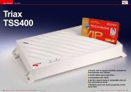
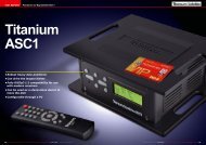
1: Intermodulation occurs directly next to the wanted signal - see<br />
the red labled signals<br />
2: The compression point is defined to be at exactly 1 dB. From<br />
here on the signal quality deviates from the ideal characteristic.<br />
that <strong>WORK</strong> Microwave incorporated<br />
two independent<br />
synthesizers in the <strong>Handheld</strong><br />
<strong>Satcom</strong> <strong>Test</strong> <strong>Source</strong> so that<br />
now you can use just a single<br />
RF signal source to perform<br />
this measurement.<br />
Obviously this greatly reduces<br />
the costs involved<br />
in acquiring these RF test<br />
sources since now you‘d only<br />
need one of these instruments<br />
instead of two. At the<br />
same time the test setup itself<br />
is simplified since only a<br />
single cable and the upconverter<br />
need to be connected.<br />
Another parameter that is<br />
measured when it comes to<br />
high-frequency converters is<br />
the so-called 1 dB compression<br />
point. This measurement<br />
is used to check the<br />
non-linear response of the<br />
high-frequency converter.<br />
Here the amplitude of the input<br />
signal is slowly increased<br />
until the signal distortion<br />
due to non-linearity deviates<br />
exactly 1 dB from the ideal<br />
characteristic curve (see<br />
Figure 2).<br />
The red line shows the<br />
ideal output curve. Above a<br />
specific input level the highfrequency<br />
converter begins<br />
to distort the signal such<br />
that a lower signal level is<br />
available at the output -<br />
hence the name “Compression“:<br />
a lower signal level is<br />
at the output; the signal has<br />
been compressed.<br />
To be able to compare different<br />
devices, you measure<br />
the input power level that<br />
results in a 1 dB compression<br />
at the output. Here<br />
the <strong>WORK</strong> Microwave <strong>Test</strong><br />
<strong>Source</strong> proves itself with the<br />
ability to set the test signal<br />
to any frequency from 50 to<br />
180 MHz and 950 to 2150<br />
MHz with a power level from<br />
100 TELE-audiovision International — The World‘s Largest Digital TV Trade Magazine — 11-12/2013 — www.TELE-audiovision.com
-45 dBm to -5 dBm in 0.5 dB<br />
steps.<br />
Another parameter to<br />
check with high-frequency<br />
converters is the conversion<br />
gain. Just like with the<br />
measurement of the 1 dB<br />
compression point, a signal<br />
with a known signal level is<br />
supplied to the converter.<br />
A spectrum analyzer would<br />
then be used to measure the<br />
signal level at the output.<br />
Of course, you could also<br />
supply a real signal and<br />
measure this. But due to<br />
several factors this measurement<br />
would not be as<br />
precise, that‘s why it‘s necessary<br />
to use a calibrated RF<br />
test source.<br />
In all of these applications<br />
<strong>WORK</strong> Microwave has shown<br />
that it has developed a fully<br />
featured and well thought<br />
out instrument: two independent<br />
synthesizers can<br />
supply two signals simultaneously<br />
in order to measure<br />
intermodulation.<br />
The <strong>Handheld</strong> <strong>Satcom</strong> <strong>Test</strong><br />
<strong>Source</strong>‘s freely selectable<br />
output level makes it possible<br />
to measure the 1 dB<br />
compression point and also<br />
gives you the ability to measure<br />
the conversion gain.<br />
Handling the <strong>WORK</strong> Microwave<br />
<strong>Handheld</strong> <strong>Satcom</strong> <strong>Test</strong><br />
<strong>Source</strong> is further simplified<br />
61<br />
4<br />
2<br />
5<br />
3<br />
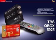
1. The application that controls the <strong>Handheld</strong> <strong>Satcom</strong><br />
test source is an easy to use tool which basically<br />
consists of this main window. Thumbs up for the nice<br />
graphical scheme, that perfectly explains what each<br />
parameter and button is used for.<br />
2. First you need to connect the software with the<br />
<strong>Test</strong> <strong>Source</strong>. This takes exactly 5 seconds and both<br />
Windows XP and Windows 7 did install the instrument<br />
automatically without the need to provide any drivers.<br />
3. Once the instrument is connected, the status in the<br />
upper part of the window is updated. In this case, the<br />
power is provided through two USB cables.<br />
4. The sweep generator opens in a separate window<br />
and allows users to specify frequency range, the up<br />
and down increment and speed, as well as the pause<br />
between sweeps.<br />
5. It is of course possible to use the <strong>Handheld</strong> <strong>Satcom</strong><br />
<strong>Test</strong> <strong>Source</strong> without a connected laptop. You just<br />
need to set up the desired parameters and store them<br />
in the instrument. When you then turn it on, it will use<br />
these parameters automatically. Great if you need to<br />
measure several devices with the same input signal.<br />
102 TELE-audiovision International — The World‘s Largest Digital TV Trade Magazine — 11-12/2013 — www.TELE-audiovision.com
y two additional details: a<br />
rechargeable battery lets<br />
you use the instrument for<br />
hours at a time without being<br />
1<br />
connected to a power source<br />
and since the test parameters<br />
can be stored in the unit<br />
itself, no connection to a laptop<br />
is needed, for example, on which a calibrated 10 MHz<br />
when the conversion gain on signal is provided so that the<br />
multiple units is measured. RF technology of different<br />
Another plus is the BNC jack devices can be controlled.<br />
4 5<br />
<strong>Test</strong> Equipment<br />
Calibration<br />
In the last issue of TELEaudiovision<br />
we tested the<br />
Deviser S7000 TV analyzer.<br />
We were very impressed<br />
with this analyzer; it comes<br />
with every possible feature<br />
that you could possibly want<br />
in a TV tester and analyzer.<br />
Even its measurement precision<br />
was able to go toe to toe<br />
with our reference devices.<br />
With the <strong>WORK</strong> Microwave<br />
<strong>Handheld</strong> <strong>Satcom</strong> <strong>Test</strong><br />
<strong>Source</strong> we wanted to know<br />
for sure: how precise are<br />
the Deviser S7000 measurements<br />
really?<br />
The <strong>Handheld</strong> <strong>Satcom</strong> <strong>Test</strong><br />
<strong>Source</strong>’s output impedance<br />
is specified at 50 Ohms while<br />
the S7000 is at 75 Ohms as<br />
is typical for TV applications.<br />
Therefore an HP impedance<br />
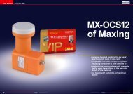
1. The <strong>Handheld</strong> <strong>Satcom</strong><br />
<strong>Test</strong> <strong>Source</strong> is configured<br />
to generate a signal at 1000<br />
MHz with -15 dBm and the<br />
Deviser S7000 correctly shows<br />
the signal at this frequency.<br />
However, the units are shown<br />
in dBµV as I forgot to configure<br />
them properly.<br />
2. Fortunately, the<br />
Deviser S7000 allows the<br />
measurements to be shown in<br />
dBµV, dBmV or dBm. The latter<br />
one is what I need.<br />
3. And now the Deviser S7000<br />
is showing the measurement<br />
value of -16.5dBm. The<br />
deviation of -1.5 dBm is not a<br />
measurement error but rather<br />
the effect of having too much<br />
signal level on the cable I am<br />
using.<br />
4. Reducing the signal<br />
output to -35 dBm on the test<br />
source produces a readout of<br />
-35.9 dBm. Excellent result,<br />
considering these two devices<br />
are manufactured at opposite<br />
sides of the world.<br />
5. The <strong>Handheld</strong> <strong>Satcom</strong><br />
<strong>Test</strong> <strong>Source</strong> can actually<br />
output two different signals<br />
simultaneously. Here I<br />
configured one -35 dBm signal<br />
at 1000 MHz and the other at<br />
1100 MHz with -15 dBm.<br />
Again, this signal level is<br />
correctly identified and<br />
confirmed by the Deviser<br />
S7000. Simply brilliant.<br />
2<br />
■<br />
The setup to test and evaluate the<br />
<strong>WORK</strong> Microwave <strong>Handheld</strong> <strong>Satcom</strong><br />
<strong>Test</strong> <strong>Source</strong>. Notice the 50 Ohm to 75<br />
Ohm impedance matching adapter from<br />
HP. <strong>Test</strong>s confirmed the theory: in our<br />
case the error was insignificant, so I<br />
dispensed the use of the adapter.<br />
3<br />
104 TELE-audiovision International — The World‘s Largest Digital TV Trade Magazine — 11-12/2013 — www.TELE-audiovision.com<br />
www.TELE-audiovision.com — 11-12/2013 — TELE-audiovision International — 全 球 发 行 量 最 大 的 数 字 电 视 杂 志 105
6<br />
8<br />
10<br />
7<br />
9<br />
6. Now for something<br />
completely different. At 75<br />
MHz a signal of -35 dBm is<br />
generated and measured<br />
with a deviation less<br />
than 1 dBm. Absolutely<br />
amazing.<br />
7. Since the Deviser S7000<br />
supports two markers<br />
in CATV mode which is<br />
used to measure the tilt<br />
between two channels, I<br />
generated one signal at 80<br />
MHz with -35 dBm and a<br />
second signal at 100 MHz<br />
with -45 dBm. Incredibly,<br />
the deviation was -0.1<br />
dBm and -0.2 dBm,<br />
respectively. The tilt was<br />
measured with 9.9 dB.<br />
8. To test the end of scale<br />
I generated a signal at 2000 MHz with -15 dBm. Again the Deviser<br />
S7000 measured this signal with an amazing precision.<br />
9. To test the sweep generator several slop step intervals had to be<br />
tested in order to allow the spectrum analyzer function to sample<br />
enough data to correctly measure the signal.<br />
10. With a slop step interval of 500 ms the Deviser S7000 produced<br />
good results so I started the test run.<br />
11. First I measured the whole spectrum with the MAX function<br />
active. This way we can see the whole range at the end of the test.<br />
The result is excellent with the spectrum oscillating about 3 dB<br />
around -35 dBm, which is the output level setup on the <strong>Handheld</strong><br />
<strong>Satcom</strong> <strong>Test</strong> <strong>Source</strong>. This oscillation is an acceptable error and<br />
due to the fact that I was giving the spectrum analyzer just about<br />
the time to render the spectrum.<br />
12. This picture shows the same output signal, but this time the<br />
signal had to pass a multi switch and about 20 meter of cable, an<br />
aerial socket and then another cable before reaching the spectrum<br />
analyzer. Notice that only the upper curve is of interest. The result<br />
is clear to see: there is an over attenuation of about 10 dB to 15 dB.<br />
Also, it is clear to see that the attenuation is not uniform.<br />
11<br />
12<br />
and is the result of the application<br />
of international standards<br />
in development and<br />
production.<br />
The pictures show the<br />
measured values in the<br />
ranges 50 to 180 MHz and<br />
950 to 2150 MHz. These are<br />
definitely within the precision<br />
range of the device and<br />
the tolerance given in the<br />
<strong>WORK</strong> Microwave <strong>Handheld</strong><br />
<strong>Satcom</strong> <strong>Test</strong> <strong>Source</strong>‘s certificate.<br />
This shows that the <strong>Handheld</strong><br />
<strong>Satcom</strong> <strong>Test</strong> <strong>Source</strong><br />
can be used in another outstanding<br />
way: it can be used<br />
to precisely calibrate test<br />
equipment.<br />
<strong>Test</strong>ing<br />
a CATV Cable Run<br />
Another application for<br />
the <strong>Handheld</strong> <strong>Satcom</strong> <strong>Test</strong><br />
<strong>Source</strong> is the testing of a<br />
CATV network‘s cable installation.<br />
For this test we used<br />
our own distribution network<br />
here in the TELE-audiovision<br />
test center.<br />
A multiswitch with 16 inputs<br />
for the satellite range<br />
(950 - 2150 MHZ) and another<br />
input for terrestrial<br />
TV (50 - 850 MHz) was used<br />
for distribution. The signal<br />
is then made available on<br />
eight outputs and distributed<br />
throughout the house to<br />
a number of antenna ports<br />
that each provide separate<br />
satellite and CATV outputs.<br />
The next step was to measure<br />
the attenuation of the<br />
signals in the satellite range,<br />
but we also wanted to know<br />
if the multiswitch, the coax<br />
cable and the antenna jacks<br />
had more of an affect on<br />
some frequencies than on<br />
others.<br />
Normally, you’d use a<br />
noise generator for this task<br />
but they typically don’t come<br />
with the same measurement<br />
precision as does the <strong>Handheld</strong><br />
<strong>Satcom</strong> <strong>Test</strong> <strong>Source</strong>.<br />
If you’re thinking now<br />
that it would be an enormous<br />
amount of work in that<br />
you’d have to check each<br />
frequency individually, you’d<br />
be wrong. <strong>WORK</strong> Microwave<br />
incorporated a sweep generator<br />
in the <strong>Handheld</strong> <strong>Satcom</strong><br />
<strong>Test</strong> <strong>Source</strong> that can be<br />
set to run through a userdefined<br />
frequency range (50<br />
to 180 MHz and 950 to 2150<br />
MHz). The frequency steps<br />
can also be set (minimum of<br />
0.5 MHz) as well as the desired<br />
speed (starting at 10<br />
ms per step).<br />
The output level can be<br />
set from -5 to -45 dBm. The<br />
sweep itself can be run bidirectionally:<br />
when the sweep<br />
reaches the upper frequency<br />
limit, it turns around<br />
converter (part number<br />
08590-60090) designed for<br />
the 1 MHz to 1.8 GHz range<br />
was used. This converter has<br />
an attenuation of -15 dBm.<br />
The <strong>WORK</strong> Microwave<br />
<strong>Handheld</strong> <strong>Satcom</strong> <strong>Test</strong><br />
<strong>Source</strong> shows here that this<br />
professional signal analyzer<br />
can perform measurements<br />
with a deviation of less than<br />
1 dB. This is extremely low<br />
106 TELE-audiovision International — The World‘s Largest Digital TV Trade Magazine — 11-12/2013 — www.TELE-audiovision.com<br />
www.TELE-audiovision.com — 11-12/2013 — TELE-audiovision International — 全 球 发 行 量 最 大 的 数 字 电 视 杂 志 107
and goes back the other<br />
way whereby the frequency<br />
steps (MHz) and sweep<br />
speed (ms) can be set up<br />
separately. You can also set<br />
up a pause between the two<br />
sweeps.<br />
The <strong>Handheld</strong> <strong>Satcom</strong><br />
<strong>Test</strong> <strong>Source</strong> was connected<br />
to the input of the multiswitch<br />
which would then<br />
operate the switch using<br />
the frequency sweep generator.<br />
The spectrum analyzer<br />
mode was activated<br />
on the test equipment and<br />
it was used with the peaklevel<br />
hold function activated<br />
in order to be able to read<br />
the results of the frequency<br />
sweeps across the entire<br />
frequency range.<br />
The first attempt failed<br />
because we didn‘t realize<br />
that the spectrum analyzer<br />
needs a certain sampling<br />
period to be able to generate<br />
a spectrum from the signal.<br />
If the signal generator<br />
sweep is too fast, it doesn‘t<br />
allow enough time for the<br />
analyzer to correctly measure<br />
the signal.<br />
So we first had to directly<br />
connect the signal generator<br />
to the analyzer and try a few<br />
different scenarios to determine<br />
the correct parameters<br />
for the frequency sweep.<br />
It quickly became clear<br />
why <strong>WORK</strong> Microwave incorporated<br />
so many parameters<br />
in the <strong>Handheld</strong> Sat-<br />
■Setup to measure the<br />
attenuation and other<br />
problems in our SAT and<br />
CATV distribution system.<br />
Luckily, the <strong>Handheld</strong> <strong>Satcom</strong><br />
<strong>Test</strong> <strong>Source</strong> works on battery.<br />
108 TELE-audiovision International — The World‘s Largest Digital TV Trade Magazine — 11-12/2013 — www.TELE-audiovision.com
1<br />
5<br />
2<br />
3<br />
1. <strong>Test</strong>ing the DVB-T USB dongle with SDR# at 50<br />
MHz. The signal is clean and correctly tuned on the<br />
supposed frequency.<br />
2. Same test, but now on 120 MHz. This frequency<br />
band is used for air control communications and it is<br />
good to see that the DVB-T USB dongle behaves very<br />
well here.<br />
3. At 180 MHz the reception is acceptable, albeit<br />
the gain is lower. The indicated dB value is just a<br />
reference as the RTL2832U chip and the FC0012 tuner<br />
have automatic gain control activated.<br />
4. Unfortunately my DVB-T USB dongle has the FC0012<br />
tuner instead of the much better E4000 one. The result<br />
is a total deafness at 950 MHz.<br />
5. As expected, no signal at 1200 MHz, either.<br />
6. At 118 MHz frequent radio communications between<br />
pilot and tower can be heard as the test centre is<br />
located near the local airport. Using the <strong>Handheld</strong><br />
<strong>Satcom</strong> <strong>Test</strong> <strong>Source</strong> I can be sure that my DVB-T USB<br />
dongle is capable of tuning and demodulating this<br />
frequency.<br />
7. I did not have to wait long to get to hear a pilot<br />
reporting to the tower. Notice the small red line<br />
at 118.000 MHz in the waterfall graph. It suddenly<br />
appears with the communication and lasts only a few<br />
seconds. This kind of air traffic communication is<br />
naturally modulated in AM and it is incredible that a<br />
DVB-T USB receiver for less than 20 Euro can actually<br />
be used as a SDR radio scanner to receive such<br />
communications.<br />
6<br />
7<br />
4<br />
com <strong>Test</strong> <strong>Source</strong>: they really<br />
are all necessary and useful.<br />
The desired measurement<br />
was taken with the following<br />
parameters:<br />
- Start frequency: 950 MHz<br />
- End frequency: 2150MHz<br />
- Frequency step: 1 MHz<br />
- Time interval per step:<br />
500 ms<br />
- Signal level: -35 dBm<br />
These values allowed the<br />
analysis of the entire satellite<br />
frequency range and the<br />
fluctuations in the directly<br />
connected analyzer turned<br />
out to be approximately +/-<br />
3 dBm.<br />
Since the <strong>WORK</strong> Microwave<br />
<strong>Handheld</strong> <strong>Satcom</strong> <strong>Test</strong><br />
<strong>Source</strong> is a portable unit with<br />
built-in rechargeable batteries,<br />
it was easy to transport<br />
it to the switch box and then<br />
put it to work. It was simply<br />
connected to a Netbook and<br />
operated without a power<br />
connection.<br />
The built-in rechargeable<br />
batteries in the signal generator<br />
let you operate with a<br />
laptop for longer periods of<br />
time without a power connection<br />
since the signal generator<br />
won’t suck the laptop<br />
battery dry if you don’t use<br />
both of the USB connections<br />
on the <strong>Handheld</strong> <strong>Satcom</strong><br />
<strong>Test</strong> <strong>Source</strong> (the second USB<br />
connection serves exclusively<br />
to recharge the battery).<br />
The measurement of the<br />
complete spectrum with<br />
these parameters needed<br />
about five minutes. During<br />
this time you could confidently<br />
focus<br />
your attention on<br />
something else<br />
because if the<br />
test is longer, the<br />
measurements<br />
would simply be repeated<br />
continuously.<br />
The results of these measurements<br />
show that there‘s<br />
a signal attenuation of 10<br />
dB to 15 dB through the<br />
signal distribution system.<br />
These are overall good values<br />
considering that there’s<br />
over 20 meters of cable, a<br />
multiswitch, an antenna jack<br />
and some more cable between<br />
the <strong>Handheld</strong> <strong>Satcom</strong><br />
<strong>Test</strong> <strong>Source</strong> and the Deviser<br />
S7000.<br />
But this measurement<br />
does point out a rather annoying<br />
aspect of this setup:<br />
the signal attenuation is not<br />
constant across the entire<br />
frequency range, but rather,<br />
some frequency segments<br />
are more strongly attenuated<br />
than others.<br />
There‘s no question: the<br />
<strong>WORK</strong> Microwave <strong>Handheld</strong><br />
<strong>Satcom</strong> <strong>Test</strong> <strong>Source</strong> makes<br />
it possible for an installer<br />
to check out an installation<br />
before the actual signals are<br />
sent through it while at the<br />
same time the quality of the<br />
system can be confidently<br />
verified using a certified reference<br />
signal.<br />
The emphasis here is on<br />
“certified” and “reference”:<br />
with the <strong>Handheld</strong> <strong>Satcom</strong><br />
<strong>Test</strong> <strong>Source</strong> there are no<br />
longer any discussions about<br />
error tolerances.<br />
<strong>Test</strong>ing<br />
an SDR Receiver<br />
We even stumbled across<br />
an unusual application for<br />
the <strong>Handheld</strong> <strong>Satcom</strong> <strong>Test</strong><br />
<strong>Source</strong>: the DVB-T COFDM<br />
demodulator built in to many<br />
USB DVB-T receivers, the<br />
Realtek RTL2832U, can also<br />
be used for radio reception<br />
because this chip makes<br />
available the raw I/Q samples.<br />
The thought here was to<br />
be able to demodulate DAB,<br />
110 TELE-audiovision International — The World‘s Largest Digital TV Trade Magazine — 11-12/2013 — www.TELE-audiovision.com<br />
www.TELE-audiovision.com — 11-12/2013 — TELE-audiovision International — 全 球 发 行 量 最 大 的 数 字 电 视 杂 志 111
DAB+ and FM yet with the<br />
matching drivers you can<br />
also use USB DVB-T receivers<br />
with Software Defined<br />
Radio (SDR); using special<br />
SDR software like SDR# you<br />
get a real scanner radio with<br />
which for example you could<br />
tune into air traffic control.<br />
The problem though is<br />
the built-in tuner in the<br />
USB DVB-T receiver. Different<br />
chips are used here, for<br />
example, the FC0012 and<br />
FC0013 models. One of the<br />
USB receivers in our test<br />
center has the FC0012 tuner.<br />
Unfortunately, these tuners<br />
are limited to the 50 to<br />
950 MHz frequency range<br />
but it‘s the 117 to 137 MHz<br />
aircraft band that‘s especially<br />
interesting. Our test center<br />
was thus outfitted with a<br />
proper antenna and using an<br />
Icom R3 we could listen in to<br />
the aircraft band.<br />
Since there aren‘t continuous<br />
transmissions on these<br />
frequencies and since I wanted<br />
to more closely analyze<br />
the sensitivity and reception<br />
capabilities of the USB receiver,<br />
it was once again time<br />
to put the <strong>Handheld</strong> <strong>Satcom</strong><br />
<strong>Test</strong> <strong>Source</strong> to work.<br />
The test setup was extremely<br />
simple: the USB<br />
DVB-T receiver was connected<br />
to a PC and installed with<br />
the special SDR drivers that<br />
can be found in the Internet<br />
under the name ”Zadig“.<br />
This freely available SDR#<br />
software was automatically<br />
recognized by the USB receiver<br />
with its RT-L2832U<br />
chips and just like that the<br />
signal can be displayed on<br />
the PC as a spectrum. Demodulation<br />
takes place in<br />
the modulations typical for<br />
a scanner radio: AM, FM, CW<br />
etc., whereby the bandwidth<br />
can be individually set.<br />
On the <strong>Handheld</strong> <strong>Satcom</strong><br />
<strong>Test</strong> <strong>Source</strong> a variety of frequencies<br />
were tried between<br />
50 and 180 MHz with emphasis<br />
on frequencies from 117<br />
to 137 MHz.<br />
The results can be seen in<br />
the pictures and vary from<br />
spectacular to disappointing.<br />
The resolution of the signal<br />
displayed by the <strong>Handheld</strong><br />
<strong>Satcom</strong> <strong>Test</strong> <strong>Source</strong> was excellent.<br />
In the aircraft frequency<br />
band it appeared<br />
that the USB DVB-T receiver<br />
would be able to provide<br />
a usable signal so the next<br />
step was to connect it to<br />
the outdoor antenna. Sure<br />
enough, after only a few<br />
minutes an aircraft could be<br />
heard making an approach<br />
to an airport.<br />
The disappointment came<br />
about because the USB DVB-<br />
T receiver in no way could<br />
receive this popular frequency<br />
band correctly. The<br />
signal from the <strong>Handheld</strong><br />
112 TELE-audiovision International — The World‘s Largest Digital TV Trade Magazine — 11-12/2013 — www.TELE-audiovision.com
expert<br />
OPINION<br />
<strong>WORK</strong> Microwave<br />
<strong>Test</strong> Signal Generator<br />
RECOMMENDED<br />
PRODUCT BY<br />
Vitor Martins<br />
Augusto<br />
<strong>Test</strong> Center<br />
Portugal<br />
<strong>Satcom</strong> <strong>Test</strong> <strong>Source</strong> was<br />
also received on the wrong<br />
frequencies; this clearly<br />
shows a problem with the<br />
DVB-T tuner. Above 950 MHz<br />
that FC0012 tuner was sure<br />
enough not able to receive<br />
any kind of usable signal<br />
even though these frequencies<br />
could easily be entered.<br />
Conclusion<br />
Even though the manufacturer<br />
only suggests using<br />
the test source to test highfrequency<br />
converters, it can<br />
also be used in many other<br />
applications. When you‘re<br />
dealing with test equipment<br />
calibration, problems due to<br />
interference signals or locating<br />
the source of unwanted<br />
signal attenuation, such a<br />
test signal source would be<br />
worth every penny. You can<br />
directly measure what‘s going<br />
on with a known signal.<br />
We were very impressed<br />
by the unbelievable precision<br />
of the <strong>Handheld</strong> <strong>Satcom</strong><br />
<strong>Test</strong> <strong>Source</strong>. Together with<br />
its certificate, it would be the<br />
perfect tool for smaller operations<br />
to verify the precision<br />
of their test equipment, calibrate<br />
them and create certified<br />
protocols that would<br />
withstand any kind of scrutiny.<br />
<strong>WORK</strong> Microwave, with<br />
their <strong>Handheld</strong> <strong>Satcom</strong> <strong>Test</strong><br />
<strong>Source</strong>, has developed an<br />
unusual instrument designed<br />
specifically for use by technicians.<br />
Instead of a large and<br />
heavy instrument chained to<br />
an electric power cord, you<br />
have a compact, portable<br />
unit that you can hold in your<br />
hands and that runs on rechargeable<br />
batteries. It‘s a<br />
device that will quickly become<br />
part of many different<br />
operations.<br />
+ ● Compact and portable test source<br />
● Two synthesizers for simultaneous generation of two signals<br />
● Configurable sweep generator<br />
● Extremely high accuracy<br />
● Provided with compliance certificate, containing detailed<br />
information about the instruments precision<br />
● Easy to use software, no installation required<br />
● No driver installation required, device recognized by Windows<br />
as Human Input Device<br />
● Internal battery<br />
–<br />
● Parameters have to be confirmed with ENTER key<br />
● Sweep Modus does not show current Frequency<br />
Manufacturer<br />
TECHNICAL<br />
DATA<br />
<strong>WORK</strong> Microwave, Germany<br />
Tel. + 49-8024-6408-27<br />
Internet<br />
Model<br />
Frequency range<br />
Frequency resolution<br />
Output level<br />
Output level resolution<br />
Level tolerance<br />
Output impedance<br />
Output mute<br />
Reference Output<br />
Temperature range<br />
www.work-microwave.de<br />
RF Signal Generator<br />
50 MHz to 180 MHz and 950 MHz to 2150 MHz<br />
0.5 MHz<br />
-45 dBm to -5 dBm<br />
0.5 dB<br />
± 1 dB<br />
50 Ohm<br />
< -60 dBc<br />
10 MHz, -10 dBm to +10 dBm, 0.5 dB steps<br />
0°C to +50°C<br />
Interface USB 2.0<br />
Power supply<br />
Power consumption<br />
Connectors<br />
Weight<br />
Dimensions (L x W x H)<br />
ext. 24 V DC, USB, internal Battery<br />
max. 12 W<br />
RF out: 50 Ohm SMA female<br />
REF out: 50 Ohm BNC-female<br />
USB 2.0: USB Standard type B<br />
1.5 kg<br />
250 x 125 x 74 mm<br />
114 TELE-audiovision International — The World‘s Largest Digital TV Trade Magazine — 11-12/2013 — www.TELE-audiovision.com