Introduction to computer systems architecture and programming
Introduction to computer systems architecture and programming
Introduction to computer systems architecture and programming

Create successful ePaper yourself
Turn your PDF publications into a flip-book with our unique Google optimized e-Paper software.
168 <strong>Introduction</strong> <strong>to</strong> <strong>computer</strong> <strong>systems</strong> <strong>architecture</strong> <strong>and</strong> <strong>programming</strong><br />
XOR opera<strong>to</strong>r<br />
A (input) B (input) C (output)<br />
TRUE TRUE FALSE<br />
TRUE FALSE TRUE<br />
FALSE TRUE TRUE<br />
FALSE FALSE FALSE<br />
Table 2.3: The Boolean operation XOR.<br />
NOT opera<strong>to</strong>r<br />
A (input)<br />
C (output)<br />
TRUE<br />
FALSE<br />
FALSE<br />
TRUE<br />
Table 2.4: The Boolean operation NOT.<br />
Note: You can also think of A <strong>and</strong> B as statements that can be TRUE or<br />
FALSE. For example, A could be the TRUE statement ‘5 > 3’. However,<br />
these statements may also contain variables, e.g. B might be the statement<br />
‘X is a prime number’ which is TRUE or FALSE depending on the value of<br />
X. You will use these kinds of statements in some of your <strong>programming</strong><br />
techniques later.<br />
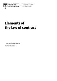
Let us now consider the gate again. A gate has one or more inputs <strong>and</strong><br />
produces exactly one output. Input <strong>and</strong> output can be at one of two<br />
different voltage levels, which in turn represent 1 <strong>and</strong> 0 (or TRUE <strong>and</strong><br />
FALSE). In this way logic gates can perform logical operations; that is, you<br />
can think of them as boxes which receive multiple inputs <strong>and</strong> produce one<br />
output according <strong>to</strong> the truth tables above (Brookshear 2009). Figure 2.1<br />
gives you the st<strong>and</strong>ard gate representations for the Boolean operations<br />
introduced in this chapter.<br />
inputs<br />
NOT<br />
output<br />
inputs<br />
AND<br />
output<br />
inputs<br />
OR<br />
output<br />
inputs<br />
XOR<br />
output<br />
Figure 2.1: Gate symbols for Boolean opera<strong>to</strong>rs.<br />
Several gates (i.e. permutations of NOT, AND, OR, XOR) can then be<br />
arranged <strong>to</strong> create circuits that can perform logical <strong>and</strong> also arithmetic<br />
operations like adding two numbers. For example, if we combine an XOR<br />
gate with an AND gate as shown below, we get what is referred <strong>to</strong> as a<br />
half adder. The half adder adds the two binary digits A <strong>and</strong> B. Different<br />
combinations of inputs A <strong>and</strong> B result in the sum of inputs A <strong>and</strong> B <strong>and</strong> the<br />
overflow:<br />
28