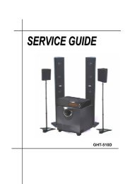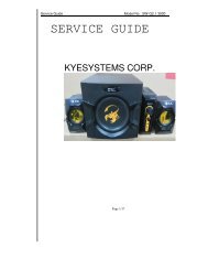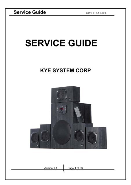
SW-HF 5.1 4500 SERVICE GUIDE.pdf - Genius
SW-HF 5.1 4500 SERVICE GUIDE.pdf - Genius
SW-HF 5.1 4500 SERVICE GUIDE.pdf - Genius

Create successful ePaper yourself
Turn your PDF publications into a flip-book with our unique Google optimized e-Paper software.
Service Guide <strong>SW</strong>-<strong>HF</strong> <strong>5.1</strong> <strong>4500</strong><br />
<strong>SERVICE</strong> <strong>GUIDE</strong><br />
KYE SYSTEM CORP<br />
Version 1.1 Page 1 of 33
Service Guide <strong>SW</strong>-<strong>HF</strong> <strong>5.1</strong> <strong>4500</strong><br />
Revision History<br />
Version Date Change<br />
1.0 23/12/2010<br />
Version 1.1 Page 2 of 33
Service Guide <strong>SW</strong>-<strong>HF</strong> <strong>5.1</strong> <strong>4500</strong><br />
Table of Contents<br />
Revision History………………………………………………………………….2<br />
Table of contents……………………………………………………………...…3<br />
Getting Start…………………………………………………….………………...4<br />
Conventions Used in this Guide…………………………………………….…4<br />
Safety Precautions………………………………………………………………4<br />
Chapter 1. How to Handle Defective Returns……………………………….5<br />
1.2 Problem………………………………………………………………………6<br />
1.2.1 No power,LED (indicator)unlighted………………………….……7<br />
1.2.2 No sound…………………………………………………………….…….8<br />
1.2.3 Front channel no sound (including either FR or FL no sound)….……9<br />
1.2.4 Rear channel no sound (including either RR or RL no sound)...……10<br />
1.2.5 Center no sound…………………………………………………………11<br />
1.2.6 Woofer no sound………………………………………………….…..…12<br />
1.2.7 Input no sound………………………………………………….……..…13<br />
1.2.8 Remote control no use………………………………….………….…...14<br />
1.2.9 Noise………………………….……………………….……………..….15<br />
1.2.10 LED indicators abnormal…………………………………….………..16<br />
1.2.11 Keystrokes in the front panel no use…………………………………17<br />
Chapter 2. Specification…………………………………………………..……18<br />
Satellite…………………………………………………………………….…….18<br />
Woofer……………………………………………………………………………19<br />
Chapter 3. Block diagram…………………………………………..………….20<br />
Chapter 4. Exploded view………………………………………………………21<br />
Subwoofer……………………………………………………………….……….21<br />
Satellite (Center)…………………………………………………..…….………22<br />
Satellite (Front)……………………………………………………..…………...23<br />
Satellite (Rear)……………………………………………………..……………24<br />
Chapter 5. Part list…………………………………… …………….…………...25<br />
Woofer………………………………………………………….………………..26<br />
Center…………………………………………………………………………...26<br />
Rear………………………………………………………………….…..……...26<br />
Front………………………………………………………………..……..……..26<br />
Chapter 6 Important notes……………………………………………………….27<br />
Chapter 7 Circuit diagram………………………………………………………..28<br />
<strong>SW</strong>-<strong>HF</strong> <strong>5.1</strong> <strong>4500</strong> MCU SCH…………………………………….…….….…………....28<br />
<strong>SW</strong>-<strong>HF</strong> <strong>5.1</strong> <strong>4500</strong> input and SPOUT SCH……… ……..……………..……..29<br />
<strong>SW</strong>-<strong>HF</strong> <strong>5.1</strong> <strong>4500</strong> SAT AMP SCH……………………………………………….30<br />
<strong>SW</strong>-<strong>HF</strong> <strong>5.1</strong> <strong>SW</strong>AMP SCH…………………………………..…………………...31<br />
<strong>SW</strong>-<strong>HF</strong> <strong>5.1</strong> <strong>4500</strong> <strong>SW</strong>AMP and Power SCH……………………………………32<br />
<strong>SW</strong>-<strong>HF</strong> <strong>5.1</strong> <strong>4500</strong> REM SCH……………………………………………………..33<br />
Version 1.1 Page 3 of 33
Service Guide <strong>SW</strong>-<strong>HF</strong> <strong>5.1</strong> <strong>4500</strong><br />
Getting Started<br />
Conventions Used in the Guide<br />
Pay Special Attention: Instructions that are important to remember and may prevent<br />
mistakes.<br />
Caution: Information that, if not followed, may result in damage to the product.<br />
Safety Precautions<br />
The following precautions should be observed in handing the speaker described in<br />
this guide:<br />
Place the speakers on a flat, level and stable surface.<br />
Do not place the speakers in environments subject to mist, smoke, vibration,<br />
excessive dust, salty or greasy air, or other corrosive gases and fumes.<br />
Do not drop or jolt the speakers.<br />
Do not allow anything to drop into the subwoofer case through its ventilator, as it<br />
could result in fatal electric shock or fire.<br />
Place the unit far enough from other equipments for good heat dissipation.<br />
Do not perform any maintenance with wet hand.<br />
Prevent foreign substance, such as water, other liquids or chemical, from entering<br />
the speakers while performing maintenance procedures on the speakers.<br />
Version 1.1 Page 4 of 33
Service Guide <strong>SW</strong>-<strong>HF</strong> <strong>5.1</strong> <strong>4500</strong><br />
Chapter 1. How to Handle Defective Returns<br />
1.1 Overview<br />
Receiving Defective speaker from customers<br />
Verifying problems<br />
Proceeding<br />
Necessary tests<br />
Function NG<br />
Function NG<br />
Function OK<br />
Analyzing possible<br />
Malfunction cause<br />
Deciding & proceeding the<br />
Rectification methods<br />
Replace necessary<br />
Defective parts<br />
Verifying problems<br />
Proceeding<br />
Necessary tests<br />
Function OK<br />
Return the speakers with proper<br />
repacking to customers<br />
Version 1.1 Page 5 of 33
Service Guide <strong>SW</strong>-<strong>HF</strong> <strong>5.1</strong> <strong>4500</strong><br />
1.2 Problems<br />
Item<br />
Problem Description<br />
1.2.1 No power,LED (indicator)<br />
1.2.2 No sound<br />
1.2.3 Front channel no sound (including either FR or FL no sound)<br />
1.2.4 Rear channel no sound (including either RR or RL no sound)<br />
1.2.5 Center no sound<br />
1.2.6 Woofer no sound<br />
1.2.7 input no sound<br />
1.2.8 Remote control no use<br />
1.2.9 Noise<br />
1.2.10 LED indicators abnormal<br />
1.2.11 Keystrokes in the front panel no use<br />
Version 1.1 Page 6 of 33
Service Guide <strong>SW</strong>-<strong>HF</strong> <strong>5.1</strong> <strong>4500</strong><br />
*Attention<br />
Please follow the numbered sequence marked within parenthesis given in<br />
individual<br />
Flow chat in that this is the best-recommended sequence to rectify the problems.<br />
1.2.1 No power,LED (indicator)unlighted<br />
Problem<br />
No power,LED (indicator)<br />
Analyze<br />
and<br />
identify<br />
the<br />
causes<br />
1. Defective transformer<br />
2. Defective or damaged<br />
AC cable or power switch<br />
1. Defective connection<br />
between <strong>SW</strong>-<strong>HF</strong><strong>5.1</strong><strong>4500</strong> MCU<br />
PCB JK3 and <strong>SW</strong>-<strong>HF</strong><strong>5.1</strong> <strong>4500</strong><br />
AMP PCB JACK1<br />
1. PCB dried soldered or broken<br />
2. Defective or damaged IC2, IC2, CR1<br />
in <strong>SW</strong>-<strong>HF</strong><strong>5.1</strong><strong>4500</strong> MCU PCB<br />
Solutions<br />
Repair or<br />
replace<br />
Repair or<br />
replace<br />
resolder or replace<br />
Version 1.1 Page 7 of 33
Service Guide <strong>SW</strong>-<strong>HF</strong> <strong>5.1</strong> <strong>4500</strong><br />
1.2.2 no sound<br />
Problem<br />
No sound<br />
Analyze and<br />
identify the<br />
causes<br />
1. PCB damaged, dry-soldered or<br />
short-circuited<br />
2. Assembled wires loosely- connected<br />
between <strong>SW</strong>-<strong>HF</strong><strong>5.1</strong> <strong>4500</strong> MCU PCB<br />
JK3 and <strong>SW</strong>-<strong>HF</strong><strong>5.1</strong> <strong>4500</strong> AMP PCB<br />
1. Defective IC or IC2 on<strong>SW</strong>-<strong>HF</strong><strong>5.1</strong> <strong>4500</strong>MCU<br />
PCB<br />
2. Defective :IC3, IC16,R111,R112,R108,<br />
EC36,EC38, EC39,in <strong>SW</strong>-<strong>HF</strong><strong>5.1</strong> <strong>4500</strong> AMP<br />
PCB<br />
]<br />
Solutions<br />
Resolder or replace<br />
Check and replace defective<br />
IC or components.<br />
Version 1.1 Page 8 of 33
Service Guide <strong>SW</strong>-<strong>HF</strong> <strong>5.1</strong> <strong>4500</strong><br />
1.2.3 Front channel no sound (including either FR or FL no sound )<br />
Problem<br />
Front channel no sound (including either FR or FL no sound)<br />
PCB damaged,<br />
Defective connection of<br />
1.defective IC3, IC4,IC5,IC7,IC9 or<br />
dry-soldered or<br />
front speaker cables and<br />
components related in <strong>SW</strong>-<strong>HF</strong><strong>5.1</strong><br />
Analyze and<br />
short-circuited;<br />
jacks, or defective<br />
<strong>4500</strong> AMP PCB<br />
identify the<br />
speaker cables, jacks or<br />
causes<br />
front driver units<br />
Solutions<br />
Resolder<br />
replace<br />
or<br />
Re-connect<br />
replace<br />
or<br />
Check and replace<br />
defective IC or<br />
components<br />
Version 1.1 Page 9 of 33
Service Guide <strong>SW</strong>-<strong>HF</strong> <strong>5.1</strong> <strong>4500</strong><br />
1.2.4 Rear channel no sound (including either RR or RL no sound)<br />
Problem<br />
Rear channel no sound (including either RR or RL no sound)<br />
PCB<br />
damaged,<br />
Defective connection<br />
Defective<br />
1. Defective IC3, IC4,<br />
Analyze and<br />
identify the<br />
causes<br />
dry-soldered or<br />
short-circuited<br />
of rear speaker<br />
cables and jacks, or<br />
defective speaker<br />
cables, jacks or rear<br />
connection of rear<br />
audio cables, or<br />
JACK<br />
disconnected from<br />
IC6,IC10 or components<br />
related in<br />
<strong>SW</strong>-<strong>HF</strong><strong>5.1</strong> <strong>4500</strong> AMP<br />
PCB<br />
driver units<br />
PCB or defective<br />
Repair or<br />
Repair or<br />
Repair or<br />
Check and replace<br />
replacing<br />
replacing<br />
replacing<br />
defective IC or<br />
Solutions<br />
components<br />
Version 1.1 Page 10 of 33
Service Guide <strong>SW</strong>-<strong>HF</strong> <strong>5.1</strong> <strong>4500</strong><br />
1.2.5 Center no sound<br />
Problem<br />
Center no sound<br />
Analyze and<br />
identify the<br />
causes<br />
PCB<br />
dry-soldered,<br />
broken, or short<br />
circuit<br />
Defective<br />
connection of<br />
center speaker<br />
cables and<br />
Defective connection<br />
of center audio<br />
cables, or JACK<br />
disconnected from<br />
1. Defective IC3,<br />
IC4,IC5,IC11 or<br />
components related in<br />
<strong>SW</strong>-<strong>HF</strong><strong>5.1</strong> <strong>4500</strong><br />
jacks,<br />
or<br />
PCB or defective<br />
AMP PCB<br />
defective<br />
speaker cables,<br />
jacks or center<br />
driver units<br />
Check<br />
Reconnect<br />
Reconnect<br />
Check and replace defective<br />
Solutions<br />
soldering<br />
points on<br />
or replace<br />
or replace<br />
IC or components<br />
PCB, and<br />
resolder<br />
Version 1.1 Page 11 of 33
Service Guide <strong>SW</strong>-<strong>HF</strong> <strong>5.1</strong> <strong>4500</strong><br />
1.2.6 Woofer no sound<br />
Problem<br />
Woofer no sound<br />
Analyze and<br />
identify the<br />
causes<br />
PCB<br />
dry-soldered,<br />
broken, or<br />
short circuited<br />
Defective<br />
connection of sub<br />
speaker cables<br />
and jacks, or<br />
defective speaker<br />
cables, jacks or<br />
Defective connection<br />
of woofer audio<br />
cables, or JACK<br />
disconnected from<br />
PCB or defective<br />
1. Defective IC3,<br />
IC4,IC7,IC8,IC12 or<br />
components related in<br />
<strong>SW</strong>-<strong>HF</strong><strong>5.1</strong> <strong>4500</strong> AMP<br />
PCB<br />
woofer driver units<br />
Repair<br />
Reconnect<br />
Reconnect<br />
Check and replace defective IC<br />
Solutions<br />
or replace<br />
or replace<br />
or components<br />
-<br />
Version 1.1 Page 12 of 33
Service Guide <strong>SW</strong>-<strong>HF</strong> <strong>5.1</strong> <strong>4500</strong><br />
1.2.7 Input no sound<br />
Problem<br />
Input no sound<br />
Analyze and<br />
TV(CD/MP3)<br />
input no sound<br />
GAME input no<br />
sound<br />
DVD input no<br />
sound<br />
identify the<br />
causes<br />
1. Defective input RCA jack<br />
1. Defective input RCA jack<br />
1. Defective input RCA jack<br />
2. Defective IC3 in<br />
2. Defective IC3 in<br />
2. Defective IC3 in<br />
<strong>SW</strong>-<strong>HF</strong><strong>5.1</strong><br />
<strong>4500</strong>AMP<br />
<strong>SW</strong>-<strong>HF</strong><strong>5.1</strong><br />
<strong>4500</strong>AMP<br />
<strong>SW</strong>-<strong>HF</strong><strong>5.1</strong><br />
<strong>4500</strong>AMP<br />
PCB or TV- input-related<br />
PCB or GAME -<br />
PCB or DVD- input-related<br />
components<br />
input-related components<br />
components<br />
Solutions<br />
Check<br />
replace<br />
and<br />
Check<br />
replace<br />
and<br />
Check<br />
replace<br />
and<br />
Version 1.1 Page 13 of 33<br />
Service Guide <strong>SW</strong>-<strong>HF</strong> <strong>5.1</strong> <strong>4500</strong>
1.2.8 Remote control no use<br />
Problem<br />
Remote control no use<br />
Analyze and<br />
identify the<br />
causes<br />
1. Low power supply<br />
of the battery<br />
2.Defective<br />
soldering of battery<br />
spring<br />
Remote PCB<br />
broken, or its IC or<br />
other components<br />
defective<br />
Defective<br />
conductive rubber<br />
of some keys<br />
Defective<br />
or<br />
dry-soldered REM1,<br />
IC2,R1,EC1,CC1 in<br />
<strong>SW</strong>-<strong>HF</strong><strong>5.1</strong> <strong>4500</strong> MCU<br />
PCB<br />
Replace or<br />
Check<br />
and<br />
Check and<br />
Check and<br />
Solutions<br />
repair<br />
replace<br />
replace<br />
replace<br />
Version 1.1 Page 14 of 33<br />
Service Guide <strong>SW</strong>-<strong>HF</strong> <strong>5.1</strong> <strong>4500</strong>
1.2.9. Noise<br />
Problem<br />
Noise<br />
Analyze and<br />
identify the<br />
causes<br />
Broken or dry-soldered<br />
PCB, or diode damaged<br />
The power supply of IC is<br />
normal or not<br />
1. Defective driver units<br />
2. Or caused by the vibration<br />
from the too long lead wire of<br />
the driver units<br />
Resolder or replace Check and replace Resolder or replace<br />
Solutions<br />
Version 1.1 Page 15 of 33<br />
Service Guide <strong>SW</strong>-<strong>HF</strong> <strong>5.1</strong> <strong>4500</strong>
1.2.10. LED indicators abnormal<br />
Problem<br />
LED indicators no light<br />
Analyze and<br />
identify the<br />
causes<br />
1. Defective, dry-soldered, or broken <strong>SW</strong>-<strong>HF</strong><strong>5.1</strong> <strong>4500</strong> MCU<br />
PCB<br />
2. LED1, IC2, IC1 damaged<br />
3. R3-R10 <strong>SW</strong>-<strong>HF</strong><strong>5.1</strong> <strong>4500</strong> MCU PCB<br />
Solutions<br />
Check and replace<br />
Version 1.1 Page 16 of 33
Service Guide <strong>SW</strong>-<strong>HF</strong> <strong>5.1</strong> <strong>4500</strong><br />
Chapter 2. Specifications<br />
Satellite<br />
NO DESCRIPTION UNIT<br />
NOMINAL<br />
CEN FR FL<br />
LIMIT<br />
1 RATED OUTPUT POWER @THD 10% W 16 16 16 ≧15.5<br />
2 SENSITIVITY (1KHz) @RATED O/P POWER m V 500 600 600 ±10%<br />
3 SENSITIVITY (1KHz) @1W O/P POWER m V 100 120 120 ±10%<br />
4 MAX INPUT LEVEL@1% THD m V 380 430 430 ±10%<br />
5<br />
FREQUENCY RESPONSE(1KHz -3DB )<br />
LOW<br />
Hz 95 95 95 ±10<br />
6 FREQUENCY RESPONSE(1KHz -3DB ) HI KHz 360 400 400 ±20<br />
7 S/N@RATED O/P POWER d B 84.5 84.5 84.5 ≧70<br />
8 CHANNEL UNBALANCE @REF O/P POWER d B 0.2 0.2 ≦0.5<br />
9<br />
CHANNEL SEPARATION(ONE<br />
CHANNELIN;OTHER CHANNEL INPUT<br />
d B 54.5 54.5 ≧40<br />
SHORTING<br />
10<br />
HUM NOISE (VOLUME MAX;INPUT<br />
SHORTING)<br />
m V 0.6 0.6 0.6 ≦2<br />
11<br />
HUM NOISE (VOLUME MIN INPUT<br />
SHORTING)<br />
m V 0.5 0.5 0.5 ≦1<br />
Version 1.1 Page 18 of 33
Service Guide <strong>SW</strong>-<strong>HF</strong> <strong>5.1</strong> 500<br />
Chapter 2 Specifications<br />
Woofer<br />
NO DESCRIPTION UNIT NOMINAL LIMIT<br />
1 RATED OUTPUT POWER@100Hz(10%THD) W 45 ≧42.5<br />
2 SENSITVITY(100Hz)@RATED O/P POWER m V 130 ±30<br />
3 SENSITIVITY(100Hz)@1W O/P POWER m V 18 ±5<br />
4 MAX INPUT LEVEL@1% THD m V 100 ±15<br />
5 DISTORTION@100Hz REF O/P POWER % 0.1 ≦0.5<br />
6<br />
FREQUENCY RESPONSE (100Hz<br />
-3DB)LOW<br />
Hz 22 ±5<br />
7 FREQUENCY RESPONSE (100Hz -3DB)HI Hz 145 ±15<br />
8 S/N RATIO@100Hz RATED O/P POWER d B 82 ≧70<br />
9 VR MIN NOISE (INPUT SHORTING) m V 0.5 ≦1<br />
10 VR MAX NOISE &HUM (INPUT SHORTING) m V 1 ≦2<br />
Version 1.1 Page 19 of 33
Service Guide <strong>SW</strong>-<strong>HF</strong> <strong>5.1</strong> <strong>4500</strong><br />
Chapter 3 Block diagram<br />
Version 1.1 Page 20 of 33
Service Guide <strong>SW</strong>-<strong>HF</strong> 5.5005<br />
Chapter 4 Exploded view<br />
Subwoofer<br />
Version 1.1 Page 21 of 33
Service Guide <strong>SW</strong>-<strong>HF</strong> <strong>5.1</strong> <strong>4500</strong><br />
Chapter 4 Exploded view<br />
Satellite (Center)<br />
Version 1.1 Page 22 of 33
Service Guide <strong>SW</strong>-<strong>HF</strong> <strong>5.1</strong> <strong>4500</strong><br />
Chapter 4 Exploded view<br />
Satellite (Front)<br />
Version 1.1 Page 23 of 33
Service Guide <strong>SW</strong>-<strong>HF</strong> <strong>5.1</strong> <strong>4500</strong><br />
Chapter 4 Exploded view<br />
Satellite (Rear)<br />
Version 1.1 Page 24 of 33
Service Guide <strong>SW</strong>-<strong>HF</strong> <strong>5.1</strong> <strong>4500</strong><br />
Chapter 5 Part list<br />
Woofer<br />
Ref. NO Description Part NO<br />
1 Front Panel EP40360361<br />
2 Transparent LED cover EP41410038<br />
3 plastic post for LED EP41410033<br />
4 big keystroke on the front panel EP40716215<br />
5 small keystrokeS on the front panel EP40714221A<br />
6 <strong>SW</strong>-<strong>HF</strong><strong>5.1</strong> <strong>4500</strong> MCU 94HB PCBA EP15<strong>4500</strong>02<br />
7 Wooden woofer cabinet EP53<strong>4500</strong>01B<br />
8 heat sink (radiator) EP23011054<br />
9 <strong>SW</strong>-<strong>HF</strong><strong>5.1</strong> <strong>4500</strong> AMP 94V0 PCBA EP15<strong>4500</strong>01<br />
10 <strong>SW</strong>-<strong>HF</strong><strong>5.1</strong> <strong>4500</strong> metal back cover EP21100087<br />
11 power switch EP19030008<br />
12 black cable pull- relief EP41610059<br />
13 transformer, 230V/50HZ/12V*2-3.5A/76*35 型 EP13500091<br />
14 bass tube -1 EP41510022<br />
15 basstube -2 EP41510040<br />
16 rubber feet, φ18*3MM EP73060098<br />
17 driver unit, A-170-5 EP16060004<br />
18 black metal grill EP61000143<br />
Version 1.1 Page 25 of 33
Service Guide <strong>SW</strong>-<strong>HF</strong> <strong>5.1</strong> <strong>4500</strong><br />
Chapter 5 Part list<br />
Center<br />
Ref. NO Description Part NO<br />
1 satellite ring EP40910425<br />
2 cloth grill EP64000204A<br />
3 driver unit, A-78-44 EP16030086<br />
4 wooden center satellite, 067 EP53Y06701B<br />
5 LOGO plate EP41260069<br />
6 ruuber feet, φ12*2MM EP73060099<br />
Rear<br />
Ref. NO Description Part NO<br />
1 satellite ring EP40910423<br />
2 cloth grill EP64000204A<br />
3 driver unit, A-78-43 EP16030085<br />
4 wooden Rear cabinet , 066 EP53Y06601B<br />
5 LOGO plate EP41260069<br />
6 rubber feet, φ12*2MM EP73060099<br />
Front<br />
Ref. NO Description Part NO<br />
1 satellite ring EP40910423<br />
2 cloth grill EP64000204A<br />
3 driver unit, A-78-43 EP16030085<br />
4 wooden front cabinet, 068 EP53Y06801B<br />
5 LOGO plate EP41260069<br />
6 rubber plate, φ12*2MM EP73060099<br />
Version 1.1 Page 26 of 33
Service Guide <strong>SW</strong>-<strong>HF</strong> <strong>5.1</strong> <strong>4500</strong><br />
Chapter 6. Important Notes<br />
6.1 Packing requirement for sending the PCB assembly by post<br />
PCB assembly is a kind of sophisticated electronic circuit board.<br />
Well packing will be required when sending them by post.<br />
*Some sophisticated IC components are mounted on the PCB<br />
assembly; hence it is necessary to pack each PCB assembly<br />
with a separate static protecting bag, in order to avoid static<br />
electricity.<br />
*Reliable external packing is also very important when sending<br />
the PCB assembly by post, in that it would avoid unnecessarily<br />
lost or damage.<br />
6.2 Short of spare parts while repairing a speaker system<br />
If you are short of spare parts when you have some speaker<br />
systems waiting to be repaired, it would be recommended to take<br />
the necessary parts from one<br />
Speaker system, so that you may have the as many speaker<br />
systems<br />
Version 1.1 Page 27 of 33
Service Guide <strong>SW</strong>-<strong>HF</strong> <strong>5.1</strong> <strong>4500</strong><br />
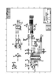
Chapter 7. Schematic diagram<br />
<strong>SW</strong>-<strong>HF</strong> <strong>5.1</strong> <strong>4500</strong> MCU SCH<br />
Version 1.1 Page 28 of 33
Service Guide <strong>SW</strong>-<strong>HF</strong> <strong>5.1</strong> <strong>4500</strong><br />
Chapter 7. Schematic diagram<br />
<strong>SW</strong>-<strong>HF</strong> <strong>5.1</strong> <strong>4500</strong> input and SPOUT SCH<br />
Version 1.1 Page 29 of 33
Service Guide <strong>SW</strong>-<strong>HF</strong> <strong>5.1</strong> <strong>4500</strong><br />
Chapter 7. Schematic diagram<br />
<strong>SW</strong>-<strong>HF</strong> <strong>5.1</strong> <strong>4500</strong> SAT AMP SCH<br />
Version 1.1 Page 30 of 33
Service Guide <strong>SW</strong>-<strong>HF</strong> <strong>5.1</strong> <strong>4500</strong><br />
Chapter 7. Schematic diagram<br />
<strong>SW</strong>-<strong>HF</strong> <strong>5.1</strong> <strong>SW</strong>AMP SCH<br />
Version 1.1 Page 31 of 33
Service Guide <strong>SW</strong>-<strong>HF</strong> <strong>5.1</strong> <strong>4500</strong><br />
Chapter 7. Schematic diagram<br />
<strong>SW</strong>-<strong>HF</strong> <strong>5.1</strong> <strong>4500</strong> <strong>SW</strong>AMP and Power SCH<br />
Version 1.1 Page 32 of 33
Service Guide <strong>SW</strong>-<strong>HF</strong> <strong>5.1</strong> <strong>4500</strong><br />
Chapter 7. Schematic diagram<br />
<strong>SW</strong>-<strong>HF</strong> <strong>5.1</strong> <strong>4500</strong> REM SCH<br />
Version 1.1 Page 33 of 33