S7000, Analyseur TV de Deviser

You also want an ePaper? Increase the reach of your titles
YUMPU automatically turns print PDFs into web optimized ePapers that Google loves.
RAPPORT DE TEST<br />
<strong>Analyseur</strong> numérique <strong>de</strong> signaux <strong>TV</strong> multi standards<br />
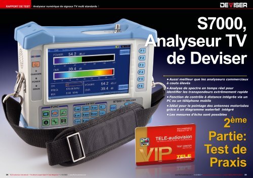
<strong>S7000</strong>,<br />
<strong>Analyseur</strong> <strong>TV</strong><br />
<strong>de</strong> <strong>Deviser</strong><br />
• Aussi meilleur que les analyseurs commerciaux<br />
à couts élevés<br />
• Analyse <strong>de</strong> spectre en temps réel pour<br />
i<strong>de</strong>ntifier les transpon<strong>de</strong>urs extrêmement rapi<strong>de</strong><br />
• Fonction <strong>de</strong> contrôle à distance intégrée via un<br />
PC ou un téléphone mobile<br />
• Idéal pour le pointage <strong>de</strong>s antennes motorisées<br />
grâce à un diagramme waterfall intégré<br />
• Les mesures d'écho sont possibles<br />
2 ème<br />
Partie:<br />
Test <strong>de</strong><br />
Praxis<br />
34 TELE-audiovision International — The World‘s Largest Digital <strong>TV</strong> Tra<strong>de</strong> Magazine — 11-12/2013 — www.TELE-audiovision.com<br />
www.TELE-audiovision.com — 11-12/2013 — TELE-audiovision International — 全 球 发 行 量 最 大 的 数 字 电 视 杂 志 35
TEST REPORT<br />
Multi Norm Digital <strong>TV</strong> Signal Analyzer<br />
Professional<br />
Combination Signal<br />
Analyzer for All Digital<br />
<strong>TV</strong> Standards<br />
■<br />
TELE-audiovision's<br />
Technical Editor<br />
Vitor Martins<br />
Augusto using the<br />
<strong>Deviser</strong> <strong>S7000</strong><br />
TEST REPORT<br />
Multi Norm Digital <strong>TV</strong> Signal Analyzer<br />
<strong>Deviser</strong> <strong>TV</strong><br />
Analyser<br />
<strong>S7000</strong><br />
Part 1: Analyzer<br />
Functions<br />
• Very large, high resolution display<br />
• Suitable for MPEG2 and MPEG4<br />
• Real-time spectrum for quickly<br />
i<strong>de</strong>ntifying active transpon<strong>de</strong>rs<br />
• Can be remotely controlled via PC<br />
or mobile phone<br />
• Very ergonomical and practical<br />
operation<br />
14 TELE-audiovision International — The World‘s Largest Digital <strong>TV</strong> Tra<strong>de</strong> Magazine — 09-10/2013 — www.TELE-audiovision.com<br />
www.TELE-audiovision.com — 09-10/2013 — TELE-audiovision International — 全 球 发 行 量 最 大 的 数 字 电 视 杂 志 15<br />
■<br />
Part 1 of this test report appeared in the 09-10/2013 issue of<br />
TELE-audiovision. It can be read online here:<br />
www.TELE-audiovision.com/TELE-audiovision-1309/eng/<strong>de</strong>viser1.pdf<br />
36 TELE-audiovision International — The World‘s Largest Digital <strong>TV</strong> Tra<strong>de</strong> Magazine — 11-12/2013 — www.TELE-audiovision.com
4<br />
While we introduced<br />
the functions of this new<br />
<strong>Deviser</strong> <strong>S7000</strong> analyzer<br />
in the previous issue of<br />
TELE-audiovision, in this<br />
second part we want to<br />
reveal to you the results<br />
of our actual testing and<br />
also present our comparison<br />
to a number of other<br />
reference analyzers.<br />
The <strong>Deviser</strong> <strong>S7000</strong> is an<br />
amazing signal analyzer<br />
that can <strong>de</strong>modulate, measure<br />
and analyze nearly<br />
every possible <strong>TV</strong> signal.<br />
There are numerous familiar<br />
measurements and then<br />
also a number of seldom<br />
used measurements available<br />
to the technician.<br />
The integrated transport<br />
stream analyzer also makes<br />
this <strong>de</strong>vice interesting for<br />
use in head-end stations<br />
since, for example, it would<br />
be able to troubleshoot any<br />
problems in newly muxed<br />
transport streams. To properly<br />
test all of the different<br />
functions in the <strong>S7000</strong>, we<br />
created a number of different<br />
scenarios in our test<br />
■<br />
Modulation<br />
DVB-S<br />
DVB-S2<br />
DVB-T<br />
DVB-C<br />
Analog<br />
Measurement<br />
center and constructed<br />
tasks for the analyzer to<br />
<strong>de</strong>al with.<br />
The first thing you‘d expect<br />
with a professional analyzer<br />
is very high precision;<br />
you want to be able to trust<br />
the values that are measured.<br />
That‘s why we measured<br />
a number of different<br />
signal sources with five different<br />
reference analyzers<br />
and compared the results to<br />
the <strong>S7000</strong>. The five reference<br />
analyzers that we used<br />
were higher-end <strong>de</strong>vices.<br />
As you can see in the following<br />
table, the <strong>S7000</strong>‘s<br />
measurement values are<br />
very similar to those of the<br />
five reference <strong>de</strong>vices.<br />
The fact that that <strong>Deviser</strong><br />
is serious about its measurement<br />
precision is confirmed<br />
not once but twice<br />
in the <strong>S7000</strong>‘s configuration<br />
menu: you can see the date<br />
of the most recent calibration<br />
and there‘s also the<br />
ability to synchronize the<br />
<strong>S7000</strong>‘s measurement values<br />
on your own so that you<br />
can, for example, guarantee<br />
that all of your company‘s<br />
<strong>Deviser</strong><br />
<strong>S7000</strong><br />
analyzers will perform i<strong>de</strong>ntical<br />
measurements.<br />
Exercise:<br />
Fine-tuning<br />
a Motorized<br />
100cm<br />
Offset Antenna<br />
Aligning an antenna with<br />
the <strong>S7000</strong> is extremely easy<br />
since this analyzer confirms<br />
its own position through the<br />
inclu<strong>de</strong>d GPS antenna and<br />
automatically displays elevation,<br />
azimuth and LNB<br />
skew for the selected satellite.<br />
The setup of the new antenna<br />
therefore turned out<br />
to be unspectacular and the<br />
strongest satellites could<br />
immediately be received<br />
after which a fine-tuning of<br />
the antenna was all that remained<br />
to be done.<br />
And it‘s here where the<br />
<strong>Deviser</strong> <strong>S7000</strong> could really<br />
prove itself; the presentation<br />
of waterfall diagrams<br />
makes this otherwise cumbersome<br />
job a piece of cake.<br />
Simply move the antenna<br />
Reference 1 Reference 2 Reference 3 Reference 4 Reference 5<br />
Power 76.9 dBµV 75.6 dBµV 77.0 dBµV 73.0 dBµV 76.0 dBµV 75.0 dBµV<br />
MER 14.9 dB - 12.5 dB 12.0 dB 17.1 dB 14.9 dB<br />
CBER
Exercise:<br />
Troubleshooting<br />
- Interference<br />
in a Home‘s<br />
CA<strong>TV</strong> Distribution<br />
In our Portuguese test<br />
center CA<strong>TV</strong> and satellite<br />
<strong>TV</strong> are available over a common<br />
cable. The coax cable<br />
from the CA<strong>TV</strong> provi<strong>de</strong>r is<br />
first run through a splitter<br />
with one of the outputs going<br />
to a DOCSIS mo<strong>de</strong>m to<br />
provi<strong>de</strong> broadband Internet<br />
access. The second splitter<br />
output goes to a multiswitch<br />
that takes the CA<strong>TV</strong> signal of<br />
50-850 MHz and combines<br />
it with the satellite signal<br />
of 950-2100 MHz from Astra<br />
19.2E, Hotbird 13.0E and<br />
Hispasat 30.0W.<br />
All of a sud<strong>de</strong>n, only weak,<br />
static-filled analog CA<strong>TV</strong><br />
could be received at all the<br />
■<br />
Checking a<br />
Multiswitch<br />
with the <strong>Deviser</strong><br />
<strong>S7000</strong><br />
■Table 2: Correct alignment of the motor and antenna: all the<br />
satellites are on the antenna's arc<br />
Faulty alignment of the motor and antenna<br />
Motor axis<br />
inclination<br />
Antenna<br />
inclination<br />
Motor<br />
alignment<br />
Too high<br />
Outer satellites cannot be received (antenna too<br />
high)<br />
No satellites can be received (antenna too high)<br />
Left satellites can’t be received because antenna is<br />
too low; right satellites can’t be received because<br />
antenna is too high<br />
cable jacks while the satellite<br />
signal could not be received<br />
at all.<br />
Here comes the <strong>S7000</strong>. On<br />
the first cable port there was<br />
no digital cable signal at all<br />
and also no satellite signal.<br />
Using an analog transpon<strong>de</strong>r<br />
the problem was quickly<br />
found: the coax cable was<br />
Too low<br />
Outer satellites cannot be received (antenna too low)<br />
No satellites can be received (antenna too low)<br />
Left satellites can’t be received because antenna is<br />
too high; right satellites can’t be received because<br />
antenna is too low<br />
not correctly connected to<br />
the cable port.<br />
Nevertheless, there still<br />
was intermittent interference.<br />
A Barscan of the CA<strong>TV</strong><br />
channels showed a significant<br />
reduction in the signal<br />
level/performance (<strong>de</strong>pending<br />
on whether it‘s an<br />
analog or digital signal) and<br />
the constellation diagram<br />
showed wi<strong>de</strong>ly scattered<br />
clouds rather than the usual<br />
focused image points for<br />
each quadrant.<br />
This situation could also<br />
be measured on another antenna<br />
jack and this led to the<br />
conclusion that the problem<br />
was not with the cable or the<br />
antenna jacks. Next the distribution<br />
cabinet was opened<br />
and the analyzer was connected<br />
directly to one of the<br />
multiswitch outputs. Once<br />
again the same problem was<br />
observed.<br />
Since the attached satellite<br />
antenna and especially<br />
the LNBs have not been<br />
serviced in some time, we<br />
began to suspect that one<br />
40 TELE-audiovision International — The World‘s Largest Digital <strong>TV</strong> Tra<strong>de</strong> Magazine — 11-12/2013 — www.TELE-audiovision.com
9<br />
12<br />
10<br />
13<br />
11<br />
14<br />
or more connectors had become<br />
oxidized or that an LNB<br />
was <strong>de</strong>fective. The LNBV<br />
output cables were therefore<br />
connected individually<br />
to the <strong>S7000</strong> and discovered<br />
that each of the polarizations<br />
from the three Quattro LNBs<br />
could be perfectly received.<br />
Could the multiswitch be<br />
<strong>de</strong>fective? When the CA<strong>TV</strong><br />
cable was connected directly<br />
from the splitter to the<br />
analyzer, some light could<br />
now be shed on the problem:<br />
interference could also<br />
be seen here even though<br />
the multiswitch wasn‘t being<br />
used. The problem could<br />
then only be with the signal<br />
from the provi<strong>de</strong>r; or could it<br />
be the splitter?<br />
When the cable from the<br />
provi<strong>de</strong>r was directly connected<br />
to the analyzer, there<br />
CA<strong>TV</strong><br />
9. An analogue picture like this<br />
is normally an indication that<br />
something is <strong>de</strong>finitely wrong<br />
with the cable. And yes: even<br />
today it is still important to be<br />
able to measure analogue CA<strong>TV</strong><br />
channels and to show a live picture.<br />
10. The vi<strong>de</strong>o and audio signal<br />
level is far too low.<br />
11. Same problem with the channel<br />
to noise ratio.<br />
12. After opening the aerial<br />
socket and reconnecting the<br />
coaxial cable properly, reception<br />
was apparently back to normal.<br />
13. Still I was getting intermittent<br />
picture interferences. There was<br />
another additional problem.<br />
14. The constellation diagram<br />
shows a less <strong>de</strong>fined and concentrated<br />
cloud – a clear indication<br />
that the signal modulation<br />
was not OK.<br />
15. The culprit was a <strong>de</strong>fect<br />
signal splitter. After exchanging<br />
it, the constellation diagram<br />
showed perfectly concentrated<br />
clouds.<br />
16. The signal quality was back<br />
to normal and without any interferences.<br />
15<br />
16<br />
42 TELE-audiovision International — The World‘s Largest Digital <strong>TV</strong> Tra<strong>de</strong> Magazine — 11-12/2013 — www.TELE-audiovision.com
17<br />
20<br />
21<br />
was no problem receiving<br />
analog and digital cable <strong>TV</strong><br />
signals. The problem was<br />
<strong>de</strong>finitely with the splitter<br />
and not with the provi<strong>de</strong>r.<br />
Fortunately, there‘s always<br />
a few replacement parts lying<br />
around so after replacing<br />
the splitter with a new one,<br />
everything once again functioned<br />
normally.<br />
In these fault scenarios it<br />
was <strong>de</strong>monstrated how beneficial<br />
it would be to have<br />
an analyzer like the <strong>S7000</strong>.<br />
It has no trouble analyzing<br />
DVB-C signals in all the different<br />
modulations as well<br />
as analog and DVB-S/S2 signals.<br />
The real-time spectrum<br />
display makes it possible to<br />
i<strong>de</strong>ntify intermittent interference<br />
and, of course, the<br />
combined waterfall display is<br />
largely preferred since at the<br />
same time as the spectrum<br />
this is also retained over a<br />
period of time. In this way<br />
ten<strong>de</strong>ncies, among other<br />
things, could be recognized.<br />
This could be especially useful<br />
if the signal only slowly<br />
rises or falls off.<br />
The multiswitch could be<br />
controlled through the perfect<br />
DiSEqC implementation<br />
and the modulation quality<br />
could be checked thanks to<br />
the constellation diagram.<br />
During the tests cables were<br />
connected and disconnected<br />
without any hiccups to the<br />
<strong>S7000</strong>. All in all, the analyzer<br />
has shown itself to be very<br />
robust.<br />
The <strong>S7000</strong> is the perfect<br />
technician‘s tool for troubleshooting<br />
problems at a customer<br />
site. All the required<br />
functions are without exception<br />
correctly implemented<br />
and function as expected.<br />
Exercise:<br />
Designing<br />
a DIY<br />
DVB-T antenna<br />
In many regions DVB-T is<br />
implemented as an SFN (Single<br />
Frequency Network). All<br />
broadcasters transmit one<br />
or more transpon<strong>de</strong>rs on the<br />
same frequencies. The huge<br />
advantage here is that the<br />
remaining frequency spectrum<br />
is left for other applications.<br />
The user can move the<br />
receiver around within the<br />
region (for example, in a car)<br />
without having to change the<br />
frequency even when reception<br />
is from another transmitter.<br />
In this test we wanted to<br />
find out if the stub antennas<br />
inclu<strong>de</strong>d with the USB receiver<br />
- in this case it‘s T-dipole<br />
antennas - are matched<br />
to the country-specific DVB-<br />
T frequency. For this reason<br />
a T-dipole antenna was<br />
constructed out of wire. The<br />
length of the wire was calculated<br />
precisely for the Portuguese<br />
DVB-T frequency of<br />
754 MHz. The formulas for<br />
the DIY T-dipole are:<br />
For a DVB-T frequency of<br />
754 MHz you get an outer<br />
conductor length of 94mm<br />
and an inner conductor<br />
length of 96mm.<br />
The outer conductor length<br />
can be achieved by simply<br />
pulling back the shield on the<br />
cable to the proper length<br />
while the insulation for the<br />
inner conductor is simply removed.<br />
And there you have it, a<br />
DIY (Do-it-Yourself) DVB-T<br />
antenna for SFN reception.<br />
You can find a variety of<br />
construction i<strong>de</strong>as for these<br />
T-dipole antennas on the Internet<br />
and even for doublequad<br />
antennas that promise<br />
even better reception.<br />
But here’s the question: is<br />
our DIY antenna really better<br />
than the inclu<strong>de</strong>d stub<br />
antenna? The answer can be<br />
seen in Table 3.<br />
Sure enough, it pays to<br />
use a specialized T-Dipole<br />
antenna. However, our experiments<br />
have shown that<br />
you can simply cut off the<br />
metal sheathing.<br />
If the inner conductor is<br />
18<br />
■<br />
754 MHz<br />
Televés TDT Roof<br />
Antenna<br />
Original Antenna<br />
Optimized DIY<br />
T-Dipol Antenna<br />
Leistung 61.0dBµV 41.7dBµV 46.2dBµV<br />
MER >30 dB 23.8 dB 23.8 dB<br />
CBER
28<br />
32<br />
37<br />
Echo<br />
Measurement<br />
The <strong>Deviser</strong> <strong>S7000</strong> can<br />
also perform Echo measurements,<br />
critical for DVB-T/H.<br />
This makes it possible to<br />
optimally erect an antenna<br />
such that the interference<br />
caused by a second, more<br />
distant transmitter can be<br />
eliminated.<br />
When this second transmitter<br />
lies outsi<strong>de</strong> of the<br />
so-called Guard interval, annoying<br />
runtime <strong>de</strong>lays are<br />
the result that the <strong>de</strong>modulator<br />
can no longer compensate<br />
for. This leads to<br />
interference and, at worst,<br />
a total loss of reception. A<br />
technician armed with the<br />
<strong>S7000</strong> can solve this problem<br />
in which, for example,<br />
he can set up two antennas<br />
and offset them such that<br />
the incoming interference<br />
signals would simply cancel<br />
each other out.<br />
The principle behind this<br />
is that both antennas are<br />
aligned to the nearest transmitter<br />
and the interference<br />
coming from the distant<br />
transmitters would involve<br />
turning the antenna to receive<br />
them.<br />
If the offset of the two antennas<br />
is selected cleverly,<br />
then the signals from the<br />
two nearby antennas would<br />
add to each other while the<br />
signals from the distant<br />
transmitters would cancel<br />
each other out.<br />
Since these types of interference<br />
echoes did not<br />
exist near our test center<br />
this type of interference was<br />
not a problem here although<br />
with the <strong>S7000</strong> it would have<br />
been very easy to set up<br />
such a “double antenna”.<br />
The ability to confirm your<br />
actual position with the inclu<strong>de</strong>d<br />
GPS antenna is actually<br />
quite interesting. In this<br />
way you could use the <strong>S7000</strong><br />
to create regional reception<br />
maps.<br />
Too bad you can’t save signal<br />
strength measurements<br />
automatically with the local<br />
position so that they could<br />
later be uploa<strong>de</strong>d to a PC<br />
or exported in Google Maps<br />
format. <strong>Deviser</strong> will most<br />
likely incorporate this function<br />
in a future firmware update.<br />
This would allow you<br />
to drive around a selected<br />
region and at the end you’d<br />
have an automatically generated<br />
field strength map.<br />
Exercise:<br />
MUX analysis of<br />
a self-generated<br />
transport stream<br />
To test the <strong>Deviser</strong> <strong>S7000</strong><br />
as a <strong>TV</strong> analyzer, a scenario<br />
was set up in a head-end<br />
station. A professional IRD<br />
with an integrated multiplexer<br />
receives a transpon<strong>de</strong>r<br />
via the built-in DVB-S2<br />
tuner and from a second IRD<br />
via the ASI-IN interface. The<br />
two transpon<strong>de</strong>rs are then<br />
muxed together into a new<br />
transpon<strong>de</strong>r that is sent to<br />
the ASI output.<br />
The <strong>S7000</strong> was connected<br />
to this output with the goal<br />
29<br />
30<br />
31<br />
33<br />
34<br />
35<br />
38<br />
39<br />
40<br />
Mux TS Analyser<br />
28. In or<strong>de</strong>r to use the Transport<br />
Stream Analyser of the <strong>S7000</strong><br />
with the ASI input, you have to<br />
first enable this interface.<br />
29. By pressing the <strong>TV</strong> key on the<br />
meter, you enter the Transport<br />
Stream Analyser, which is now<br />
receiving the TS stream on its<br />
ASI input connector. In this case<br />
I setup a TS containing channels<br />
from two different German FTA<br />
transpon<strong>de</strong>rs.<br />
30. The <strong>Deviser</strong> <strong>S7000</strong> gives<br />
access to all parameters of the<br />
TS stream. 31, 32. Interestingly,<br />
the equipment used to generate<br />
this mux filtered all NIT information,<br />
which is correct. Don’t<br />
you hate receiving a CA<strong>TV</strong> transpon<strong>de</strong>r<br />
containing a satellite<br />
NIT?<br />
33. One important application<br />
for the <strong>S7000</strong>: <strong>de</strong>termining the<br />
TS rate. Notice on this picture<br />
that the specified bandwidth of<br />
the TS is 75 MB/s, but 32.45%<br />
are not being used. This clearly<br />
represents a waste of allocated<br />
bandwidth.<br />
34. I reduced the bandwidth on<br />
the multiplexer to 35 MB/s but<br />
this time the <strong>S7000</strong> indicates<br />
that there is 0% empty capacity<br />
in the stream. This means that<br />
there is no reserve for sporadic<br />
increases in bandwidth.<br />
35. Again, the multiplexer was<br />
setup, this time to use a bandwidth<br />
of 40 MB/s. And this time<br />
around 15% of the bandwidth is<br />
empty, leaving some reserve.<br />
This adjustment took a couple of<br />
minutes and resulted in saving a<br />
bandwidth of 35 MB/s.<br />
36. To compare our TS with one<br />
of the originally broadcasted<br />
streams, we connected the ASI<br />
output of one of the IRDs.<br />
37. While there is no disturbance<br />
in the PCR interval measurement<br />
in our TS…<br />
38. …some can be <strong>de</strong>tected from<br />
the satellite signal, which is<br />
normal after travelling back and<br />
forth into space. However, if the<br />
TS from our multiplexer would<br />
show a PCR like this, then something<br />
would clearly be wrong.<br />
39. Analysis of one of the original<br />
satellite Transport Streams.<br />
40. The PIDs carry different numbers…<br />
41. …and the NIT contains additional<br />
data.<br />
36<br />
41<br />
46 TELE-audiovision International — The World‘s Largest Digital <strong>TV</strong> Tra<strong>de</strong> Magazine — 11-12/2013 — www.TELE-audiovision.com<br />
www.TELE-audiovision.com — 11-12/2013 — TELE-audiovision International — 全 球 发 行 量 最 大 的 数 字 电 视 杂 志 47
44<br />
of analyzing the received<br />
transpon<strong>de</strong>r stream to, for<br />
example, check the PIDs<br />
that were being used and to<br />
measure eventual timing errors.<br />
This job is handled by<br />
the <strong>S7000</strong> effortlessly. You<br />
merely have to activate the<br />
ASI input to use the <strong>TV</strong> analyzer<br />
function with the TS<br />
stream on the ASI input.<br />
Numerous functions are now<br />
available just like in normal<br />
Tuner mo<strong>de</strong>.<br />
We could quickly <strong>de</strong>termine<br />
if the stream really<br />
consisted of all the <strong>de</strong>sired<br />
channels and services. It’s<br />
interesting to note that the<br />
IRD assigned new PIDs such<br />
that they don’t correspond to<br />
the PIDs of the original transpon<strong>de</strong>r.<br />
The <strong>S7000</strong> showed<br />
this instantly.<br />
Finally, it also pays to perform<br />
a PCR measurement:<br />
if the original satellite signal<br />
had no <strong>de</strong>viations (in the<br />
green range), the stream<br />
produced by the IRD was<br />
perfectly synchronized with<br />
the <strong>S7000</strong>’s clock generator.<br />
If there was the smallest of<br />
errors, they would have been<br />
further multiplied through<br />
additional signal distribution.<br />
The <strong>Deviser</strong> <strong>S7000</strong> is i<strong>de</strong>al<br />
for all of these tasks.<br />
<strong>S7000</strong>’s<br />
PC Software<br />
So, what software is loa<strong>de</strong>d<br />
on the inclu<strong>de</strong>d CD? The<br />
<strong>S7000</strong> Toolbox (as the software<br />
is called) lets you comfortably<br />
manage and edit<br />
numerous transpon<strong>de</strong>r and<br />
satellite lists. Additionally,<br />
measurements stored in the<br />
<strong>S7000</strong> can be presented on a<br />
PC. Not only that, measurements<br />
can be stored in two<br />
different ways.<br />
For starters the current<br />
screen image can be saved<br />
as a picture. The measurement<br />
values themselves can<br />
be stored. These measurement<br />
values could then be<br />
displayed in the PC software<br />
whereby more influence can<br />
naturally be placed on the<br />
presentation. This makes it<br />
possible to generate professional<br />
inspection reports on<br />
the computer. The technician<br />
can copy all the measurement<br />
data onto a USB stick<br />
and hand it over to his office<br />
colleagues who could then<br />
create the reports.<br />
In this way you don’t have<br />
to do the actual work on the<br />
<strong>S7000</strong> leaving it free to be<br />
42<br />
45<br />
46<br />
43<br />
Toolbox Software<br />
42. Thanks to the <strong>S7000</strong>’s Ethernet port<br />
it is possible to access the data captured<br />
through an FTP client.<br />
43. Naturally, the same can be done using<br />
the <strong>Deviser</strong> Toolbox software, which<br />
allows to edit the channel lists and satellite<br />
transpon<strong>de</strong>r as well.<br />
44. Editing the satellite transpon<strong>de</strong>r lists<br />
is really easy, but <strong>Deviser</strong> did a good job<br />
maintaining them updated, so there really<br />
was nothing to edit: the <strong>S7000</strong> features all<br />
worldwi<strong>de</strong> satellite transpon<strong>de</strong>r lists.<br />
45. Editing the terrestrial channels is no<br />
challenge either, and again all channel<br />
plans worldwi<strong>de</strong> are pre<strong>de</strong>fined.<br />
46. Amazingly, the Toolbox software is<br />
not only capable of downloading and<br />
displaying the screenshots taken during<br />
measurements. If you instead store the<br />
actual data, the measurements can be<br />
ren<strong>de</strong>red with the toolbox software instead.<br />
This provi<strong>de</strong>s additional functionality,<br />
since markers can be moved, etc. Also, the<br />
technician taking the measurements does<br />
not have to worry about specific readings<br />
for the report – they can be generated with<br />
the stored data and you don’t even need<br />
the meter to do that: just transfer the data<br />
using the network or a USB memory and<br />
the meter is ready to be used for the next<br />
call!<br />
48 TELE-audiovision International — The World‘s Largest Digital <strong>TV</strong> Tra<strong>de</strong> Magazine — 11-12/2013 — www.TELE-audiovision.com<br />
www.TELE-audiovision.com — 11-12/2013 — TELE-audiovision International — 全 球 发 行 量 最 大 的 数 字 电 视 杂 志 49
47<br />
48<br />
used on the next job.<br />
The data (settings and<br />
measurements) can be read<br />
directly as a file from a disk<br />
or via the integrated ActiveSync<br />
function via the<br />
network from the analyzer.<br />
Naturally, the files can be<br />
copied the same way from<br />
the PC back to the analyzer.<br />
The un<strong>de</strong>rlying protocol is<br />
actually the best FTP protocol<br />
and, thanks to the Wireshark<br />
network analysis tool,<br />
the access data was quickly<br />
<strong>de</strong>termined: if nee<strong>de</strong>d you<br />
can also copy the files back<br />
and forth normally via FTP<br />
where you provi<strong>de</strong> the IP address<br />
of the analyzer along<br />
with the user name „ftpadmin“<br />
and the password „Instrument“.<br />
It‘s important to operate<br />
the FTP connection in Active<br />
mo<strong>de</strong> so that files can<br />
be copied back and forth<br />
more quickly. Damage can‘t<br />
be inflicted to the <strong>de</strong>vice in<br />
this way since only the User<br />
Directory Plan, SaveBmp,<br />
SaveData and Temp are<br />
available via FTP.<br />
The highlight of the <strong>S7000</strong><br />
Toolbox Software is the remote<br />
control of the entire<br />
analyzer! Via the unremarkable<br />
„Remote Control“ button<br />
a new window is opened<br />
that then displays the front<br />
panel of the analyzer including<br />
the screen. The mouse<br />
can be used to „press“ all<br />
of the virtual buttons just<br />
like the real buttons and the<br />
screen reacts just as fast as<br />
on the real analyzer.<br />
You can access all of the<br />
functions via the network<br />
without requiring any direct<br />
access to the actual physical<br />
analyzer. Only the <strong>de</strong>modulated<br />
vi<strong>de</strong>o/audio is<br />
not passed on which is to<br />
be expected consi<strong>de</strong>ring<br />
49 50<br />
51<br />
Toolbox Software<br />
47. Incredibly, <strong>Deviser</strong> implemented<br />
a remote access to the meter. All<br />
you need is a network connection<br />
to the meter to be able to fully<br />
operate the <strong>S7000</strong> remotely.<br />
48. Everything shown on the<br />
physical screen is ren<strong>de</strong>red in real<br />
time on the remote software.<br />
49, 50. Even the TS analyser<br />
function can be used this way –<br />
only the live picture is obviously<br />
not shown, due to bandwidth<br />
limitations of the network.<br />
51. If you have a smartphone, you<br />
can do a VNC connection to the<br />
PC running the <strong>Deviser</strong> Toolbox<br />
software. This means that you can<br />
climb to the roof with just your<br />
phone and still use all functions<br />
of the <strong>S7000</strong>. This is simply<br />
incredible.<br />
50 TELE-audiovision International — The World‘s Largest Digital <strong>TV</strong> Tra<strong>de</strong> Magazine — 11-12/2013 — www.TELE-audiovision.com
the bandwidth that would be<br />
nee<strong>de</strong>d.<br />
So the question then is:<br />
why not leave the <strong>S7000</strong> in<br />
the house and only climb up<br />
on the roof with a Smart-<br />
Phone?<br />
The SmartPhone can be<br />
linked to the PC via VNC<br />
which can then be controlled<br />
remotely. If the Toolbox<br />
Software is started ahead of<br />
time, the <strong>S7000</strong> can then be<br />
comfortably controlled via<br />
the SmartPhone and thanks<br />
to its touchscreen you have<br />
access to all of the analyzer‘s<br />
virtual buttons.<br />
Just like that you have a<br />
100g (1/4 Lbs) SmartPhone<br />
in your hand and you can<br />
hang out on your roof for<br />
hours adjusting your antenna!<br />
How great is that?<br />
Perhaps <strong>Deviser</strong> will eventually<br />
offer an App for Android<br />
phones and/or iPhones<br />
so that the <strong>S7000</strong> can be<br />
controlled directly without<br />
first going through a PC.<br />
Are there any<br />
issues with<br />
the analyzer?<br />
A test in which no problems<br />
are found with a unit is<br />
not possible; it would be an<br />
indication that you haven‘t<br />
a<strong>de</strong>quately <strong>de</strong>alt with it.<br />
Even so, there is essentially<br />
nothing to complain about<br />
with the <strong>S7000</strong> so some effort<br />
had to be ma<strong>de</strong> to at<br />
least come up with the following<br />
points:<br />
• With analog CA<strong>TV</strong> signals<br />
the <strong>S7000</strong> cannot display<br />
any vi<strong>de</strong>otext. This isn‘t really<br />
critical since the analog<br />
vi<strong>de</strong>o signal can be analyzed<br />
in Oscillator mo<strong>de</strong>.<br />
• In Spectrum mo<strong>de</strong> you<br />
can‘t overlay a current<br />
spectrum with a previously<br />
stored spectrum as a reference.<br />
This could typically<br />
be used to align different<br />
antennas exactly the same<br />
and to compare the current<br />
spectrum for a longer period<br />
of time with the stored spectrum<br />
to <strong>de</strong>termine if there<br />
has been any <strong>de</strong>terioration.<br />
<strong>Deviser</strong> could more than<br />
likely add this function easily<br />
with a firmware update.<br />
• It was somewhat annoying<br />
that the <strong>S7000</strong> automatically<br />
reduces the range<br />
of the spectrum based on<br />
the incoming signal when<br />
you switch to measurement<br />
mo<strong>de</strong>. As soon as the<br />
spectrum is redisplayed, the<br />
range has to be manually adjusted<br />
in or<strong>de</strong>r to once again<br />
see the entire spectrum.<br />
This is just a minor thing and<br />
probably just as many users<br />
will appreciate this - it‘s<br />
a typical case of: you can‘t<br />
make everyone happy.<br />
But these are all minor issues.<br />
The <strong>Deviser</strong> <strong>S7000</strong> is a<br />
professional signal analyzer<br />
for practically all <strong>TV</strong> standards.<br />
It is perfectly equipped<br />
for any possible application.<br />
Every possible measurement<br />
is available. The analyzer is<br />
very easy to use, it is robust<br />
and also comes with a<br />
complete <strong>TV</strong> analyzer. The<br />
measured values remove<br />
any doubts and provi<strong>de</strong> an<br />
accuracy similar to other<br />
high-end professional signal<br />
analyzers.<br />
What more could you ask<br />
for? Perhaps, armed with the<br />
<strong>S7000</strong>, you‘d hopefully want<br />
to come across as many<br />
complex situations as possible<br />
so that you could diagnose<br />
and correct them.<br />
It‘s simply a lot of fun to<br />
work with this outstanding<br />
signal analyzer!<br />
52<br />
Battery and Insi<strong>de</strong> Peek<br />
52. The battery pack of the <strong>S7000</strong> is easily accessible on the back<br />
si<strong>de</strong> of the meter. Two big screws need to be loosened up.<br />
53. The cover plate can be removed, revealing the battery pack.<br />
54. The battery back can be pulled by the two cords. It is a composed<br />
of a 10x AA battery pack.<br />
55. We could not resist removing the cover of the meter to have a<br />
peek insi<strong>de</strong>. What we saw: a highly integrated and extremely well<br />
built electronic equipment. Naturally we did not dare to further<br />
disassemble the <strong>de</strong>vice, so this is the best insight we can provi<strong>de</strong>.<br />
53<br />
54<br />
55<br />
How to interpret BER<br />
measurements<br />
What does 1.2E-03<br />
mean? BER stands for Bit<br />
Error Ratio: the measuring<br />
instrument will basically<br />
count the erroneous<br />
bits within all received<br />
bits and calculate this<br />
simple formula:<br />
Because the amount<br />
of erroneous bits is normally<br />
very small, let’s<br />
say 1 wrong bit in every<br />
1.000.000 bits, it would<br />
look odd to see a value<br />
of 0.000001 on the<br />
meter’s screen. A much<br />
more convenient format<br />
would be 1x10⁻⁶. Calculators<br />
will frequently<br />
show this number as 1E-<br />
6, instead, to save some<br />
screen space. So this is<br />
what a reading of CBER =<br />
1.2E-03 means: you will<br />
get one wrong bit in every<br />
1200 bits received.<br />
Let’s do the math:<br />
56<br />
57<br />
Ka-Band Satellite Scan<br />
56. This waterfall diagram shows the horizon from about 30.0E to<br />
30.0W using the Inverto Ka LNB. Only 9.0E is broadcasting transpon<strong>de</strong>rs<br />
in the 19.7 GHz – 20.2 GHz range.<br />
57. This picture shows 9.0E over a period of time (about 30 seconds).<br />
The second half (lower part – representing about 15 seconds) of the<br />
waterfall diagram was recor<strong>de</strong>d during a sporadic rain shower. Curiously<br />
the rain did not produce any signal loss.<br />
CBER means that no error<br />
correction has been<br />
applied to the signal, so<br />
let’s now see what LBER<br />
< 1.0E-8 means:<br />
It means that after applying<br />
the error correction,<br />
we only will receive<br />
one bad bit every hundred<br />
million received bits.<br />
We will have a great picture<br />
without any noticeable<br />
artifacts. However,<br />
because our initial CBER<br />
value is low, there is no<br />
bad weather reserve.<br />
If the signals gets only<br />
slightly worse, the error<br />
correction will not be<br />
able to correct the incoming<br />
stream and picture<br />
artifacts will be produced.<br />
The thumb rule is: the<br />
smaller the BER value<br />
before error correction,<br />
the better. Notice that<br />
smaller means a bigger<br />
number after the “E”, because<br />
there is a “-“ sign:<br />
-5 is smaller than -3! The<br />
smaller the number, the<br />
more bad weather reserve<br />
you will get. The BER<br />
value after the error correction<br />
will give you an<br />
i<strong>de</strong>a, if artifacts will be<br />
noticeable on the screen<br />
with the current signal.<br />
52 TELE-audiovision International — The World‘s Largest Digital <strong>TV</strong> Tra<strong>de</strong> Magazine — 11-12/2013 — www.TELE-audiovision.com<br />
www.TELE-audiovision.com — 11-12/2013 — TELE-audiovision International — 全 球 发 行 量 最 大 的 数 字 电 视 杂 志 53
4<br />
DVB-S, DVB-S2, DVB-C, DVB-T,<br />
DVB-T2, DVB-H, ATSC –<br />
the <strong>Deviser</strong> <strong>S7000</strong> can do it all!<br />
The <strong>Deviser</strong> <strong>S7000</strong> is a very versatile instrument that comes<br />
from the factory with the ability to handle practically<br />
every modulation. We checked out a number of standards<br />
again to confirm that the <strong>S7000</strong> really can work with these<br />
different DVB and ATSC modulations.<br />
1, 2. In addition to DVB-T, the <strong>S7000</strong> can also analyze DVB-T2 signals<br />
and can display the corresponding constellation diagrams.<br />
Interesting with DVB-T2 is the option to introduce a slope to the<br />
modulation called TILT with which the signal can be ma<strong>de</strong> more<br />
stable against interference.<br />
3, 4. You might assume that every DVB-T compatible signal analyzer<br />
can also analyze DVB-H. We tried it out to make sure. Sure<br />
enough, the <strong>S7000</strong> can measure DVB-H without any problems.<br />
5, 6. Next is ATSC. Here‘s where the <strong>S7000</strong> shows what it‘s all<br />
about: while most competitor products nearly always offer ATSC<br />
only as an option, <strong>Deviser</strong> inclu<strong>de</strong>s it as a standard feature. Even<br />
the constellation diagram for 8VSB is correctly displayed.<br />
7, 8. Naturally the <strong>S7000</strong> can also take care of 16VSB modulation;<br />
it‘s amazing how capable this analyzer is for every possible situation.<br />
1<br />
5<br />
6<br />
2<br />
7<br />
3<br />
8<br />
54 TELE-audiovision International — The World‘s Largest Digital <strong>TV</strong> Tra<strong>de</strong> Magazine — 11-12/2013 — www.TELE-audiovision.com