2003 Enhanced Mobility Package Operator's Manual (PDF) - GM Fleet
2003 Enhanced Mobility Package Operator's Manual (PDF) - GM Fleet
2003 Enhanced Mobility Package Operator's Manual (PDF) - GM Fleet

Create successful ePaper yourself
Turn your PDF publications into a flip-book with our unique Google optimized e-Paper software.
<strong>2003</strong> <strong>Enhanced</strong> <strong>Mobility</strong> <strong>Package</strong> Operator’s <strong>Manual</strong><br />
Features and Controls........................................................2-1<br />
Windows..........................................................................2-2<br />
Starting and Operating Your Vehicle.........................2-2<br />
Tire Pressure Monitoring System Overview............2-3<br />
Programming.................................................................2-9<br />
Instrument Panel..................................................................3-1<br />
Accessory Panel Overview.........................................3-2<br />
Warning Lights, Gages and Indicators...................3-3<br />
Driving Your Vehicle............................................................4-1<br />
Towing..............................................................................4-2<br />
Loading Your Vehicle...................................................4-2<br />
<strong>Enhanced</strong> Suspension System................................4-3<br />
Underbody Protection..................................................4-3<br />
Service and Appearance Care.........................................5-1<br />
Vent Filters.....................................................................5-2<br />
Beadlock Wheels.........................................................5-2<br />
Vehicle Control Module (VCM)...................................5-3<br />
Removing the Spare Tire and Tools........................5-4<br />
Vehicle Information.......................................................5-12<br />
Capacities and Specifications..................................5-13<br />
Maintenance Schedule.......................................................6-1<br />
Maintenance Schedule................................................6-2<br />
Front/Rear Axle Inspection.........................................6-2<br />
Transfer Case Inspection..........................................6-2<br />
Customer Assistance Information..................................7-1<br />
Customer Assistance Information............................7-2<br />
Contact Information......................................................7-2<br />
i
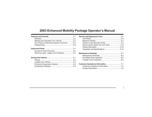
The information in this manual pertains to the<br />
operation of the vehicle. It also contains the vehicle’s<br />
scheduled maintenance services. This manual along with<br />
the owner’s manual will assist you in the proper use and<br />
maintenance of the vehicle. The sections in this<br />
supplement correspond to the sections in the <strong>2003</strong><br />
Silverado Owner’s <strong>Manual</strong> and the <strong>2003</strong> Duramax Diesel<br />
Engine Owner’s <strong>Manual</strong> Supplement.<br />
Please keep this supplement with the owner’s manual<br />
and diesel supplement in the vehicle, so it will be there<br />
if you ever need it while you’re on the road.<br />
This manual includes the latest information at the time it<br />
was printed. We reserve the right to make changes in<br />
the product after that time without notice.<br />
How to Use This <strong>Manual</strong><br />
Many people read the owner’s manual from beginning<br />
to end when they first receive the vehicle. If you do<br />
this, it will help you learn about the features and<br />
controls for the vehicle. In this manual, you’ll find that<br />
pictures and words work together to explain things.<br />
Litho in USA<br />
Part No. EMPOM03 First Edition<br />
ii<br />
©<br />
Copyright General Motors Corporation 04/08/04<br />
All Rights Reserved.
Index<br />
A good place to look for what you need is the Index in<br />
back of the manual. It’s an alphabetical list of what’s in<br />
the manual, and the page number where you’ll find it.<br />
Driving Your Vehicle<br />
As with other vehicles of this type, failure to operate this<br />
vehicle correctly may result in loss of control or an<br />
accident. Refer to “Your Driving, the Road and Your<br />
Vehicle” and “Off-Road Driving with Your Four-Wheel-Drive<br />
Vehicle” in the <strong>2003</strong> Silverado Truck Owner’s <strong>Manual</strong>.<br />
Safety Warnings and Symbols<br />
You will find a number of safety cautions in this book.<br />
We use a box and the word CAUTION to tell you about<br />
things that could cause personal injury if you were to<br />
ignore the warning.<br />
CAUTION:<br />
These mean there is something that could hurt<br />
you or other people.<br />
In the caution area, we tell you what the hazard is.<br />
Then we tell you what to do to help avoid or reduce the<br />
hazard. Please read these cautions. If you don’t, you or<br />
others could be hurt.<br />
Vehicle Damage Warnings<br />
Also, in this supplement manual you will find these<br />
notices:<br />
Notice: These mean there is something that<br />
could damage the vehicle.<br />
In the notice area, we tell you about something that can<br />
damage the vehicle. Many times, this damage would not<br />
be covered by the warranty, and it could be costly. But<br />
the notice will tell you what to do to help avoid the<br />
damage.<br />
When you read other manuals, you might see CAUTION<br />
and NOTICE warnings in different colors or in different<br />
words.<br />
You’ll also see warning labels on your vehicle.<br />
They use the same words, CAUTION or NOTICE.<br />
iii
Section 2 Features and Controls<br />
Windows...............................................................................2-2<br />
Sliding Rear Window...................................................2-2<br />
Starting and Operating Your Vehicle..............................2-2<br />
Starting Your Engine....................................................2-2<br />
Tire Pressure Monitoring System<br />
Overview..........................................................................2-3<br />
System Description......................................................2-5<br />
Monitoring System........................................................2-6<br />
Checking Tire Conditions..........................................2-7<br />
Alerts and Warnings....................................................2-7<br />
Programming ......................................................................2-9<br />
Cold Tire Inflation.........................................................2-9<br />
Low Pressure Warning..............................................2-10<br />
Pressure Deviation Alert............................................2-11<br />
Understanding Temperature<br />
Compensated Pressure Readings....................2-12<br />
High Temperature Alert..............................................2-13<br />
Measurement Selection..............................................2-13<br />
Tire Rotation Mode......................................................2-14<br />
Tire Color Codes.........................................................2-15<br />
Advanced Programming-Level 2..............................2-16<br />
Slope Mode....................................................................2-16<br />
Learn Mode....................................................................2-17<br />
Programming Using the LF Wand.........................2-18<br />
2-1
Windows<br />
Sliding Rear Window<br />
The sliding rear window features tempered glass<br />
surrounded by a durable black finish aluminum frame<br />
and three panel design. Locking latch adds cab<br />
security.<br />
To open the window hold the latch in the open<br />
position and slide window open. To close the window<br />
slide the window until the latch is fully engaged<br />
against the frame.<br />
Starting and Operating Your<br />
Vehicle<br />
Starting Your Engine<br />
The diesel engine starts differently than a gasoline<br />
engine.<br />
CAUTION:<br />
Do not use gasoline or starting “aids,” such as ether,<br />
in the air intake. They could damage your engine.<br />
There could also be a fire, which could cause serious<br />
personal injury.<br />
Refer to the <strong>2003</strong> Duramax Diesel Engine Owner’s<br />
<strong>Manual</strong> Supplement, located in your glove compartment.<br />
15030<br />
2-2
Tire Pressure Monitoring System Overview<br />
The monitoring display is designed to let you know at a glance of problems with the tires.<br />
15031<br />
2-3
The main components of the function display are the following:<br />
A. Programmed Wheel Position<br />
B. Alarm Light<br />
C. Low Pressure Warning<br />
D. Alert Indicator<br />
E. Learn Mode<br />
F. TIRE Button<br />
G. MODE Button<br />
H. Towing Vehicle Indicator<br />
I. Numerical Display<br />
J. Units of Pressure or Temperature<br />
K. Programming Mode<br />
L. Cold Pressure Indicator<br />
M. Tire Rotation Program<br />
N. Set Button<br />
2-4
System Description<br />
This system is a sensing device designed to identify and<br />
display tire operating data and activate an alert or warning<br />
when pressure or temperature irregularities are detected.<br />
It is the responsibility of the driver to react promptly and<br />
with discretion to alerts and warnings. Abnormal tire<br />
inflation pressures should be corrected at the earliest<br />
opportunity.<br />
The alerts and warnings are as follows:<br />
• The pressure deviation alert indicates that the<br />
pressure has dropped a selected amount<br />
below the required pressure for that level of tire<br />
temperature.<br />
Notice: When an alert or warning condition is detected,<br />
reduce vehicle speed to an appropriate safe level and<br />
proceed to a safe stopping location or facility where the<br />
tire can be inspected and serviced.<br />
The Full Function Display has an energy saving feature<br />
that turns lights on to full intensity (Active stage) only<br />
when required to display alert conditions or program the<br />
unit. The unit automatically switches to lower power<br />
stages when no control activity is detected.<br />
• The low pressure warning indicates that the air<br />
pressure has dropped to a selected minimum.<br />
• The high temperature warning indicates that the<br />
contained air temperature has exceeded the<br />
selected maximum. A tire temperature buildup can<br />
be caused by a number of factors including severe<br />
under inflation, hard sustained braking, vehicle<br />
overload and sustained high speeds.<br />
2-5
Monitor Operation<br />
When power is applied to the receiver, the Full Function<br />
Display momentarily turns on all icons, beeps, and the<br />
alarm light blinks once. The unit then goes into standby<br />
mode waiting for data from the wheel transmitters.<br />
Until the vehicle is in motion no data will be received<br />
from any installed transmitter. The display will remain<br />
blank.<br />
15035<br />
Data from a towed vehicle is indicated by tire icons with<br />
no windshield/louver icon.<br />
Note: The system will alternate views between the towing<br />
and towed vehicle when operating with this configuration.<br />
15034<br />
The respective tire icon is filled in as soon as data from<br />
its transmitter is received. The windshield/louver is shown<br />
for any towing vehicle transmitter. After data from all<br />
transmitters is received the display will be in the state<br />
shown until an alert or warning condition is detected.<br />
(Normal Mode)<br />
2-6<br />
15036
Checking Tire Conditions<br />
Alerts and Warnings<br />
Pressure Deviation Alert<br />
The Pressure Deviation Alert is initiated when the<br />
measured tire pressure deviates from the required<br />
pressure by more than the preset level.<br />
15037<br />
1. Press the TIRE button to scroll through<br />
the tires.<br />
2. Press the MODE button to scroll through<br />
the pressure, temperature, and pressure<br />
deviation readings for a selected tire.<br />
3. Press SET button to return to normal<br />
mode.<br />
15039<br />
The alarm light turns on and alert indicator flashes<br />
on and off. The audible alarm sounds once and the<br />
digital readout displays the amount of deviation (e.g. -6<br />
PSI (.41 Bar)) from required pressure.<br />
Press any button to acknowledge the alert and<br />
stop the flashing, the alarm light remains on and<br />
the system returns to normal mode.<br />
15038<br />
No data received from a selected tire is shown as dashes<br />
“- - -”.<br />
Example:<br />
Pressure Deviation Alert Level = + -6 PSI (.41 Bar)<br />
Required Pressure = 35 PSI (2.40 Bar)<br />
Actual Pressure in a wheel drops to 29 PSI (2 Bar)<br />
2-7
Pressure Deviation reading (as shown) will be<br />
-6 PSI (.41 Bar)<br />
When the alert occurs, reduce speed and proceed<br />
to a safe location to check tires.<br />
The Pressure Deviation Alert is cancelled when<br />
the tires are properly re-inflated to correct levels.<br />
Low Pressure Warning<br />
A Low Pressure Warning is initiated when the<br />
pressure drops below the programmed level.<br />
CAUTION:<br />
When the alert occurs, reduce speed and proceed to<br />
a safe location to check tires.<br />
Notice: The Pressure Deviation Alert is cancelled when<br />
the tires are properly re-inflated to correct levels.<br />
High Pressure Warning<br />
The High Temperature Alert is initiated when<br />
the air temperature within a tire exceeds the programmed<br />
level.<br />
15040<br />
The alarm light, low pressure warning icons and the<br />
audible alarm turn on and off continuously. Press any<br />
button to acknowledge and stop the flashing. The alarm<br />
light remains on and the display reverts to a normal<br />
mode.<br />
15041<br />
The temperature alert icon and audible alarm turn on<br />
and off continuously. Press any button to acknowledge<br />
the alert and stop the flashing. The alarm light remains<br />
on and the display reverts to a normal mode.<br />
2-8
CAUTION:<br />
When the alert occurs, reduce speed and proceed to<br />
a safe location to check tires.<br />
Indicators Displayed When in Programming Mode<br />
Level 1<br />
Cold Pressure<br />
+_ Pressure Deviation<br />
Notice: The Pressure Deviation Alert is cancelled when<br />
the tires are properly re-inflated to correct levels.<br />
Tire Rotation<br />
Low Pressure Warning<br />
°C°F High Temperature Alert<br />
Bar PSI °C°F Units Selection<br />
Programming<br />
To Enter Programming Mode<br />
SL<br />
Slope<br />
Level 2<br />
Learn Transmitter ID<br />
1. Ensure power is turned on.<br />
2. Press and hold Set button in normal mode<br />
to enter programming mode:<br />
• 2 seconds for Level 1<br />
• 5 seconds for Level 2<br />
Cold Inflation Pressure<br />
See the Tire Pressure Monitoring System Setting Chart<br />
for setting value specifications.<br />
This function changes the cold inflation pressure for<br />
each axle. Factory default setting is 30 PSI (2.08 Bar).<br />
15042<br />
2-9
Programming Steps<br />
1. Enter Level 1 Programming Mode (see Entering<br />
Programming Mode).<br />
2. Press the TIRE button to scroll to the<br />
desired axle. The tires of the selected axle<br />
are filled in.<br />
3. Press the MODE button to view the current<br />
value.<br />
Low-Pressure Warning<br />
This function changes the low-pressure warning threshold<br />
for each axle. Factory default setting is 18 PSI (1.25 Bar).<br />
See the Tire Pressure Monitoring System Setting Chart<br />
for setting value specifications.<br />
4. Press the TIRE button to increase the value.<br />
5. Press the MODE button to decrease the<br />
value.<br />
6. Press the SET button to save when the<br />
desired value is reached.<br />
Repeat programming steps 2-6 until Cold Inflation<br />
Pressure levels are set for all axles as desired.<br />
7. Press the SET button to exit.<br />
8. Press the SET button again to revert to<br />
normal view.<br />
Programming Steps<br />
15043<br />
1. Enter Level 1 Programming Mode (see Entering<br />
Programming Mode).<br />
2. To enter this function press the MODE<br />
button until the flat tire icon and pressure<br />
units are displayed.<br />
3. Press the TIRE button to scroll to the<br />
desired axle. The tires of the selected axle<br />
are filled in.<br />
2-10
Pressure Deviation Alert<br />
This function sets the pressure deviation alert threshold<br />
for all tires. Factory default setting is 5 PSI (.35 Bar).<br />
15044<br />
4. Press the MODE button to view the current<br />
value.<br />
5. Press the TIRE button to increase the value.<br />
6. Press the MODE button to decrease the<br />
value.<br />
7. Press the SET button to save when the<br />
desired value is reached.<br />
Repeat programming steps 2-7 until Low-Pressure<br />
warning levels are set for all axles as desired.<br />
8. Press the SET button to exit.<br />
9. Press the SET button again to revert to<br />
normal view.<br />
15045<br />
Programming Steps<br />
1. Enter Level 1 Programming Mode (see Entering<br />
Programming Mode).<br />
2. To enter this function press the MODE<br />
button until the flat tire icon and pressure<br />
units are displayed.<br />
3. Press the TIRE button to enter and display<br />
the current value.<br />
4. Press the TIRE button to increase the value.<br />
5. Press the MODE button to decrease the<br />
value.<br />
2-11
6. Press the MODE button until the display<br />
shows OFF to disable this feature.<br />
7. Press the SET button to save when the<br />
desired value is reached.<br />
8. Press the SET button again to revert to<br />
normal view.<br />
Understanding Temperature<br />
Compensated Pressure Readings<br />
15046<br />
An important feature of the Full Function Display system<br />
is that pressure deviation alerts are initiated from a<br />
comparison of the temperature compensated pressure<br />
to the measured tire pressure read by the sensor.<br />
“Capacities and Specifications” in the Index. When a tire<br />
heats up, the air pressure inside the tire can also be<br />
expected to increase. For example, a normal or “required”<br />
pressure at 64°F (18°C) may be 34 PSI or (2.35 Bar) and<br />
a normal pressure at 120°F (49°C) may be 39 PSI (2.7<br />
Bar). Both pressure readings are correct at their respective<br />
temperatures.<br />
The amount of deviation from the required pressure (at<br />
any temperature) can be read by using the Pressure<br />
Deviation mode of this system. If at any time you are<br />
uncertain that the Actual Pressure reading on the display<br />
indicates the correct tire pressure, switch to the Pressure<br />
Deviation ( +_ ) readout. A blank display indicates that the<br />
reading on the display is the correct one. Any (+) or (-)<br />
value indicates the tire pressure is incorrect by that value.<br />
This value can then be used to correctly inflate the tire.<br />
The reference pressure, or “cold pressure” is the air<br />
pressure inside the tire inflated at room temperature<br />
64°F (18°C) to the recommended pressure, see<br />
2-12
High Temperature Alert<br />
°C°F<br />
This function changes the high-temperature alert<br />
threshold. Factory default setting is 176°F (80°C).<br />
15048<br />
6. To disable this feature press the MODE<br />
button until the display reads OFF.<br />
15047<br />
Programming Steps<br />
1. Enter Level 1 Programming Mode (see Entering<br />
Programming Mode).<br />
2. To enter this function press the MODE<br />
button until the alert icon and temperature<br />
units are displayed.<br />
3. Press the TIRE button to enter and display<br />
the current value of High Temperature Alert.<br />
4. Press the TIRE button to increase the value.<br />
7. Press the SET button to save and exit this<br />
mode when the desired value is reached.<br />
8. Press the SET again to revert to normal<br />
mode.<br />
Measurement Selection-Metric or Imperial<br />
Use this mode to select the combination of pressure<br />
and temperature units.<br />
Unit combinations are Bar -°C, Bar -°F, PSI -°C, PSI<br />
-°F.<br />
5. Press the MODE button to decrease the<br />
value.<br />
2-13
Tire Rotation Mode<br />
This function is used after tires are rotated and the new<br />
positions need to be updated. This procedure is valid for<br />
four tire locations only.<br />
15049<br />
Programming Steps<br />
1. Enter Level 1 Programming Mode (see Entering<br />
Programming Mode).<br />
2-14<br />
2. To enter this function press the MODE<br />
button until the pressure and temperature<br />
units are displayed. (PSI/Bar, °C/°F).<br />
3. Press the TIRE button to enter.<br />
4. Use the TIRE or MODE button to scroll<br />
through the four combinations of unit<br />
settings.<br />
5. When the desired combination is displayed<br />
press the SET button to save and<br />
exit this mode.<br />
6. Press the SET button again to revert to<br />
normal mode.<br />
15050<br />
Programming Steps<br />
1. Enter Level 1 Programming Mode (see Entering<br />
Programming Mode).<br />
2. To enter this function press the MODE<br />
button until the tire rotation icon is<br />
displayed.<br />
3. Press the TIRE button to scroll to a tire<br />
position.<br />
4. Press the MODE button to select it for<br />
editing.<br />
5. Note the color of the washer on the physical<br />
tire at the currently selected position.
6. Use the tire color code table provided to<br />
determine the number corresponding to color<br />
noted in Step 5.<br />
7. Use the TIRE or MODE button to<br />
adjust the value to the number<br />
determined in step 6.<br />
8. Press the SET button when the number<br />
representing the desired sensor is achieved.<br />
This returns the display to the tire selection<br />
menu. Scroll to a different tire location and<br />
edit the sensor numbers as above.<br />
9. Press SET button to save and exit this<br />
mode.<br />
If more than one tire location contains the same<br />
sensor number, the display will prompt an error<br />
with the conflicting tires filled in and the associated<br />
sensor number. Press any button to return the tire<br />
selection menu and make necessary corrections.<br />
15052<br />
10. Press SET button again to revert to normal<br />
mode.<br />
Tire Color Codes<br />
15051<br />
Color<br />
Green<br />
Red<br />
Blue<br />
Yellow<br />
Tire Number<br />
1<br />
2<br />
3<br />
4<br />
2-15
Advanced Programming-Level 2<br />
Slope Mode SL<br />
See the Tire Pressure Monitoring System Setting Chart<br />
for setting value specifications.<br />
The Slope is a value corresponding to the rate of<br />
pressure change due to temperature for a particular tire.<br />
This value affects the calculation to determine pressure<br />
deviation value. The factory default setting is 44.<br />
15054<br />
4. Press the TIRE button to increase the value.<br />
5. Press the MODE button to decrease the<br />
value. The minimum value is 10 and the<br />
maximum is 160.<br />
6. Press the SET button to save the value.<br />
15053<br />
Programming Steps<br />
1. Enter Level 2 Programming Mode (see Entering<br />
Programming Mode).<br />
2. Press the TIRE button to scroll to the<br />
desired axle, the tires of the selected axle<br />
are filled in.<br />
Repeat steps 2-6 until the slope level is set for all axles<br />
as desired.<br />
7. Press the SET button to exit.<br />
8. Press the SET again to revert to normal<br />
mode.<br />
3. Press the MODE button to display the<br />
current value of slope for the selected axle.<br />
2-16
Learn Mode<br />
This mode is used to add or remove transmitters from<br />
the system.<br />
5. A new transmitter identification can be learned in<br />
three ways:<br />
• Vigorously shake the transmitter to provoke a<br />
transmission.<br />
• Using the LF Wand. See Programming Using<br />
the LF Wand.<br />
15032<br />
Programming Steps<br />
1. Enter Level 2 Programming Mode (see Entering<br />
Programming Mode).<br />
2. Press the MODE button to select the learn<br />
mode icon.<br />
3. Press the TIRE button to display the ten<br />
possible wheel positions for the towing<br />
vehicle. The currently installed transmitter<br />
positions are now indicated with a filled in<br />
tire indicator.<br />
4. Use the TIRE button to scroll to the desired<br />
position. The outline of the wheel position<br />
to be programmed will flash.<br />
• By inflating or deflating the tire by more than 3<br />
PSI (0.2 Bar).<br />
This method must be carried out while the transmitters<br />
are in “gage fill” mode. This mode is entered for 15<br />
minutes after the vehicle has been driven above 6 mph<br />
(10 kph). Each transmitter “learn operation” must be<br />
carried out at least 90 seconds apart. If it is not possible<br />
to complete the learn operation for all transmitters within<br />
15 minutes, the vehicle must again be driven above 6<br />
mph (10 kph) and then the process can be continued.<br />
Note: To prevent the last identification from being erased,<br />
scroll to the next tire position before driving. A beep and<br />
rapid flashing of the alarm light indicate a transmission was<br />
received. The new ID is stored.<br />
2-17
If more than one tire location contains the same sensor<br />
ID, the display will prompt an error and flash between<br />
this message and the display, with the conflicting tires<br />
filled in. If so indicated repeat the programming procedure<br />
above.<br />
15033<br />
6. To remove the transmitter from the selected<br />
tire location, press the MODE button.<br />
7. Press the TIRE button to scroll to another<br />
position and repeat step 4 or 5 as required.<br />
8. Press the SET button to save and exit.<br />
If no error is found, the system will reset and go to<br />
normal mode.<br />
15051<br />
Programming Using the LF Wand<br />
The tire pressure sensor receiver that is installed on the<br />
vehicle needs to have the unique sensor identification<br />
code for each wheel position programmed into it to<br />
ensure proper operation of the system. Each wheel<br />
assembly has a sensor in it that can be activated using<br />
the LF wand that had been supplied for this purpose.<br />
When the sensor is activated, it sends out its unique<br />
identification code which is then stored in the memory of<br />
the receiver so that it knows which sensors belong to<br />
that vehicle.<br />
The vehicle does not have to be moving to accomplish<br />
this task, which allows programming of receivers to be<br />
carried out very easily. To use the wand to activate the<br />
sensor, press the button on the side of the wand (a<br />
small red LED will illuminate to show it is working, if this<br />
does not happen then replace the batteries) and place<br />
the square head of the wand, flat against the tire side<br />
wall. The wand can activate the sensor within a 60<br />
2-18
degree arc of the sensor on the rim. If the location of the<br />
sensor is not known, the wand can be slowly moved<br />
around the circumference of the tire until the sensor is<br />
activated.<br />
The ‘Learn’ operation is carried out by using the Full<br />
Function Display that is already installed in each vehicle.<br />
15032<br />
1. Enter Level 2 Programming Mode of the Full<br />
Function Display by pressing the SET button<br />
for 5 seconds until SL can be seen in the display.<br />
2. Press the MODE button to select learn<br />
mode, which is indicated by a head with a<br />
question mark icon.<br />
3. Press the TIRE button to display the<br />
ten possible wheel positions for the towing<br />
vehicle (a windshield can also be seen to<br />
indicate that the towing vehicle is selected).<br />
4. The outline of the Front Right tire will be flashing.<br />
5. Use the LF wand to activate the sensor from the<br />
Front Right tire.<br />
6. When the sensor is activated and the ‘Learn’<br />
operation is successful, the outline of the tire is<br />
filled in and the receiver will issue a chirping<br />
sound. The red LED on the FFD will also light up.<br />
7. Press the TIRE button to move to the Front<br />
Left tire and activate the sensor in this<br />
position.<br />
8. Press the TIRE button (5 times) to move to<br />
the Rear Right tire and activate the sensor<br />
in this position.<br />
9. Press the TIRE button to the Rear Left tire<br />
and activate the sensor in this position.<br />
10. Once all 4 positions have been ‘Learned’<br />
press the SET button to store the<br />
information. The FFD will blink and the<br />
receiver will issue an audible tone to signify<br />
success.<br />
2-19
For warranty or other information, refer to the<br />
SmarTire Full Function Display User’s <strong>Manual</strong> in the<br />
vehicle’s glove compartment. For system operation or<br />
for system diagnostics refer to the <strong>2003</strong> <strong>Enhanced</strong><br />
<strong>Mobility</strong> <strong>Package</strong> Service <strong>Manual</strong> Supplement.<br />
2-20<br />
15051<br />
11. If more than one tire location contains the same<br />
sensor ID, the display will prompt an error and<br />
flash between this message and the display, with<br />
the conflicting tires filled in. If this happens, press<br />
the TIRE button and the display will show the<br />
positions with the same IDs. Use the MODE<br />
button to delete the sensor that is incorrect and<br />
then carry out the ‘Learn’ operation for that<br />
position.<br />
Notice: If a sensor is programmed into an incorrect<br />
position on the vehicle during the Learn process, it can<br />
be deleted by scrolling to the incorrect position (using<br />
the TIRE button) and pressing the MODE button.<br />
Once the Learn operation is completed as above, walk<br />
around the vehicle and activate each sensor with the<br />
wand, to double check that the sensors are in the correct<br />
position. The display should show all 4 wheel positions<br />
as expected.
NOTES<br />
2-21
Section 3 Instrument Panel<br />
Accessory Panel Overview...............................................3-2<br />
Warning Lights, Gages and Indicators..........................3-3<br />
Air Filter Restriction Indicator.....................................3-3<br />
Tire Pressure Monitoring System.............................3-3<br />
3-1
Accessory Panel Overview<br />
15148<br />
The components of the <strong>Enhanced</strong> <strong>Mobility</strong> <strong>Package</strong> instrument panel are the following:<br />
A. Accessory Panel<br />
B. Tire Pressure Monitoring Display<br />
C. Air Filter Restriction Indicator<br />
D. Accessory Power Outlet<br />
3-2
Warning Lights, Gages and Indicators<br />
Air Filter Restriction Indicator<br />
Tire Pressure Monitoring System<br />
15149 15150<br />
This vehicle is equipped with a gage located on the<br />
accessory switch panel. It monitors the engine air filter.<br />
As the filter gets dirty, the yellow indicator will begin to<br />
rise. When it reaches the top of the scale, the filter<br />
should be replaced. After replacing the filter, reset the<br />
gage by pressing in the yellow reset button at the bottom<br />
of the gage.<br />
This vehicle is equipped with a display located on the<br />
accessory switch panel in the lower center of the<br />
instrument panel. It monitors the condition of the tires.<br />
See “Tire Pressure Monitoring System Overview” for more<br />
information.<br />
3-3
Section 4 Driving Your Vehicle<br />
Towing...................................................................................4-2<br />
Towing Your Vehicle...................................................4-2<br />
Loading Your Vehicle..........................................................4-2<br />
<strong>Enhanced</strong> Suspension System.......................................4-3<br />
Underbody Protection........................................................4-3<br />
4-1
Towing<br />
Towing Your Vehicle<br />
When towing the vehicle, you should always use a<br />
properly equipped wrecker/recovery vehicle. Refer to<br />
“Towing Your Vehicle” and “Recreational Vehicle Towing”<br />
in the Index of the <strong>2003</strong> Silverado Truck Owner’s <strong>Manual</strong><br />
for further information on towing the vehicle.<br />
Notice: The steering wheel must be secured properly<br />
with the appropriate wheel-locking device to keep the<br />
wheel in the straight position. The vehicle transfer case<br />
must be in NEUTRAL (N).<br />
Loading Your Vehicle<br />
CAUTION:<br />
Do not load your vehicle any heavier than the GVWR,<br />
or either the maximum front or rear GAWR. If you do,<br />
parts on your vehicle can break, or it can change the<br />
way your vehicle handles. These could cause you to<br />
lose control. Also, overloading can shorten the life of<br />
your vehicle.<br />
Notice: Overloading your vehicle may cause damage.<br />
Your warranty does not cover parts or components that<br />
fail because of overloading. Do not overload your<br />
vehicle.<br />
Make sure that all cargo is properly secured to prevent<br />
the load from shifting. All loads must be distributed evenly<br />
over the axle and secured. Refer to “Loading Your Vehicle”<br />
in the Index of the <strong>2003</strong> Silverado Truck Owner’s <strong>Manual</strong><br />
for more information on vehicle loading.<br />
4-2
<strong>Enhanced</strong> Suspension System<br />
The enhanced suspension provides supplemental<br />
suspension modifications specially engineered for<br />
severe service on & off road. The system is<br />
comprised of a series of four (4) specially designed<br />
and critically damped hydro/pneumatic jounce shocks<br />
in parallel with the vehicles primary suspension for<br />
increased energy dissipation and greatly enhanced all<br />
terrain capability. The front and rear suspension is<br />
equipped with this feature. The front factory jounce<br />
bumper has been modified to work with this system.<br />
This system requires no maintenance or adjustments.<br />
The bumpers and struts are replaced as a unit. For<br />
replacement procedures refer to the <strong>2003</strong> <strong>Enhanced</strong><br />
<strong>Mobility</strong> <strong>Package</strong> Service <strong>Manual</strong> Supplement.<br />
Underbody Protection<br />
To protect the underside of the vehicle, multiple skid<br />
plates have been installed. The skid plates ensure<br />
that an optimal amount of the vehicle’s underside is<br />
protected from damage, but a smooth underside also<br />
assists your vehicle in sliding over obstacles it might<br />
otherwise hang up on. When in place, the multiple<br />
skid plates allow full access to maintenance items.<br />
4-3
NOTES<br />
4-4
NOTES<br />
3-4
NOTES<br />
4-5
Section 5 Service and Appearance Care<br />
Vent Filters............................................................................5-2<br />
Rear Axle Vent-Tube Filter...........................................5-2<br />
Transfer Case Vent-Tube Filter................................5-2<br />
Front Axle Vent-Tube Filter.........................................5-2<br />
Beadlock Wheels.................................................................5-2<br />
Vehicle Control Module (VCM)..........................................5-3<br />
Removing the Spare Tire and Tools.................................5-4<br />
Storing a Flat or Spare Tire, Jack and Tools........5-10<br />
Vehicle Information ............................................................5-12<br />
Government Vehicle Data Plate...............................5-12<br />
Capacities and Specifications ........................................5-13<br />
5-1
Vent Filters<br />
Rear Axle Vent-Tube Filter<br />
The rear axle vent-tube filter is located on the vent hose<br />
that is near the left jounce bumper.<br />
Refer to the Maintenance Schedule to determine how<br />
often to inspect the filter and when to change it. See Front/<br />
Rear Axle Inspection.<br />
Transfer Case Vent-Tube Filter<br />
The transfer case vent-tube filter is located on the left<br />
side of the transfer case housing.<br />
Refer to the Maintenance Schedule to determine how<br />
often to inspect the filter and when to change it. See Transfer<br />
Case Inspection.<br />
Front Axle Vent-Tube Filter<br />
The front axle vent-tube filter is located in the engine<br />
compartment near the left inner wheel well.<br />
Beadlock Wheels<br />
This vehicle is equipped with special rubber beadlock<br />
wheels. Made exclusively for use on multi-piece wheels,<br />
the device fits securely between the tire beads and<br />
positively locks the tire to the wheel rim flange. Beadlocks<br />
allow vehicle operation at the low tire air pressure<br />
conditions required for better mobility in mud, sand and<br />
snow. By reducing the air pressure, the tire footprint is<br />
increased significantly, thus allowing a greater area of<br />
traction or contact. The beadlock also performs as a<br />
safety device to ensure that the tire does not “unseat”<br />
from the rim or rotate on the wheel at these low air<br />
pressure settings, while also preventing the entry of<br />
foreign objects, debris or water into the tire’s air chamber.<br />
For tire pressures see “Capacities and Specifications” in<br />
the Index.<br />
Notice: These tires require special mounting and<br />
dismounting. Refer to the <strong>2003</strong> <strong>Enhanced</strong> <strong>Mobility</strong><br />
<strong>Package</strong> Service <strong>Manual</strong> Supplement.<br />
Refer to the Maintenance Schedule to determine how<br />
often to inspect the filter and when to change it. See Front/<br />
Rear Axle Inspection.<br />
5-2
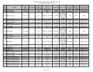
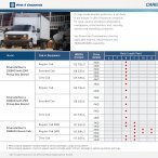
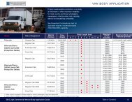
Vehicle Control Module (VCM)<br />
When tires are changed from the original equipment<br />
size to those adapted to off-road usage, the Vehicle<br />
Control Module (VCM) must be reprogrammed to correct<br />
the speedometer reading.<br />
This reprogramming will also limit maximum vehicle<br />
speed to 93 mph (150 km/h).<br />
Truck models K 2500: LLY/LB7 6.6L V8 Diesel Engine<br />
and M74 Automatic Transmission.<br />
Reprogramming the VCM is done with a TECH II<br />
electronic diagnostic system. Your <strong>GM</strong> truck dealer has<br />
this equipment. Your dealer has the correct calibration<br />
identified by the calibration part numbers on the following<br />
chart and any later updates after this publication.<br />
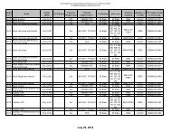
Model Year Engine Transmission New Tire Sizes *Calibration P/N<br />
<strong>2003</strong>/2004<br />
LB7<br />
M74<br />
LT285/75R16<br />
(628 Rev/Mile)<br />
(392 Rev per Kilometer)<br />
15130245<br />
2004<br />
LLY<br />
M74<br />
LT285/75R16<br />
(628 Rev/Mile)<br />
(392 Rev per Kilometer)<br />
15130246<br />
2005<br />
LT285/75R16<br />
LLY M74<br />
(628 Rev/Mile) 15130247<br />
(392 Rev per Kilometer)<br />
Please refer to the light duty series <strong>GM</strong> BODY BUILDER BOOK for further general information regarding<br />
vehicle modification.<br />
* New calibrations include maximum vehicle speed of 93 mph (150 km/h)<br />
5-3
Removing the Spare Tire and Tools<br />
15055<br />
15056<br />
The equipment is stored on the floor at the rear of the<br />
cab.<br />
1. The wheel blocks can be removed by turning the<br />
wing nut (A) counter-clockwise.<br />
2. There are also wing nuts (A) used to retain the<br />
storage bag and tools. To remove them, turn the<br />
wing nuts counter-clockwise<br />
5-4
15057<br />
3. To release the jack from<br />
its holder, turn the knob<br />
(A) on the jack holder<br />
counter-clockwise.<br />
4. Using the wheel wrench<br />
and ratchet, remove the<br />
retainer nut (B) and the<br />
retainer (A).<br />
CAUTION:<br />
To help avoid personal injury, follow all tire changing<br />
and storage instructions in this manual and the label<br />
on the jack tools storage bag. Use jack only for lifting<br />
this vehicle during tire change, never for maintenance<br />
or repairs. Never get under the vehicle while using<br />
jack.<br />
Removing the Flat Tire and Installing<br />
the Spare Tire<br />
Use the following pictures and instructions to remove<br />
the flat tire and raise the vehicle.<br />
15058<br />
5. Remove tire from the<br />
vehicle and put the spare<br />
tire near the flat tire.<br />
15059<br />
5-5
The tools you will be using include the ratchet (A), the<br />
wheel wrench (B), the wheel blocks (C), the jack (D), the<br />
jack handle (E), and the extension (F).<br />
1. Ensure that the vehicle is parked on a level surface.<br />
2. Ensure that the vehicle’s transmission is in park<br />
and the transfer case is NOT in neutral.<br />
3. Set the vehicle parking brake.<br />
15060<br />
5. Use the ratchet and wheel wrench to loosen all the<br />
wheel nuts. Turn the wheel wrench counter-clock<br />
wise to loosen the wheel nuts. Don’t remove the<br />
wheel nuts yet.<br />
4. Using the wheel blocks, block the opposite tire that<br />
is being changed.<br />
5-6<br />
15061<br />
6. Assemble the jacking components.<br />
15062
CAUTION:<br />
Getting under a vehicle when it is jacked up is<br />
dangerous. If the vehicle slips off the jack you could<br />
be badly injured or killed. Never get under a vehicle<br />
when it is supported only by a jack.<br />
CAUTION:<br />
15063<br />
7. Place the jack only at the appropriate jack point.<br />
8. Raise the tire OFF the ground.<br />
Raising your vehicle with the jack improperly<br />
positioned can damage the vehicle and even make<br />
the vehicle fall. To help avoid personal injury and<br />
vehicle damage, be sure to fit the jack lift head into<br />
the proper location before raising the vehicle.<br />
5-7
15064<br />
9. Remove all the wheel<br />
nuts and take off the<br />
flat tire.<br />
CAUTION:<br />
Rust or dirt on the wheel, or on the parts to which it<br />
is fastened, can make the wheel nuts become loose<br />
after time. The wheel could come off and cause an<br />
accident. When you change a wheel, remove any rust<br />
or dirt from the places where the wheel attaches to<br />
the vehicle. In an emergency, you can use a cloth or<br />
a paper towel to do this; but be sure to use a scraper<br />
or wire brush later, if needed, to get all the rust or dirt<br />
off.<br />
10. Remove any rust or dirt<br />
from the wheel bolts,<br />
mounting surfaces and<br />
spare wheel.<br />
CAUTION:<br />
Never use oil or grease on studs or nuts. If you do,<br />
the nuts might come loose. Your wheel could fall off,<br />
causing a serious accident.<br />
15065<br />
5-8
15066<br />
11. After mounting the<br />
spare, put the wheel<br />
nuts back on with the<br />
rounded end of the<br />
nuts toward the wheel.<br />
Tighten each wheel<br />
nut by hand. Then use<br />
the wheel wrench to<br />
tighten the nuts until<br />
the wheel is held<br />
against the hub.<br />
12. Turn the wheel wrench counter-clockwise to lower<br />
the vehicle and remove the jack.<br />
15067<br />
13. Tighten the nuts firmly in a crisscross sequence<br />
as shown by turning the wheel wrench clockwise.<br />
CAUTION:<br />
Incorrect wheel nuts or improperly tightened wheel<br />
nuts can cause the wheel to come loose and even<br />
come off. This could lead to an accident. Be sure to<br />
use the correct wheel nuts.<br />
CAUTION: (continued)<br />
5-9
CAUTION: (continued)<br />
If you have to replace them, be sure to get new <strong>GM</strong><br />
original equipment wheel nuts. Stop somewhere as<br />
soon as you can and have the nuts tightened with a<br />
torque wrench to the proper torque specification.<br />
See “Capacities and Specifications” in the Index for<br />
wheel nut torque specification.<br />
Notice: Improperly tightened wheel nuts can lead to<br />
brake pulsation and rotor damage. To avoid expensive<br />
brake repairs, evenly tighten the wheel nuts in the proper<br />
sequence and to the proper torque specification. See<br />
“Capacities and Specifications” in the Index for the wheel<br />
nut torque specification.<br />
Storing a Flat or Spare Tire, Jack and<br />
Tools<br />
CAUTION:<br />
Storing a jack, a tire, or other equipment loosely in<br />
the passenger compartment of the vehicle could<br />
cause injury. In a sudden stop or collision, loose<br />
equipment could strike someone. Store all these in<br />
the proper place.<br />
Return the jack, wheel blocks, wheel wrench and jack<br />
handle to their location on the floor at the rear of the cab.<br />
Secure the items in the vehicle as shown.<br />
5-10
1. Return the tire back<br />
into the tire support<br />
and install retainer (A),<br />
washer and retainer<br />
nut (B).<br />
15058<br />
2. Turn the nut clockwise<br />
until a minimum of 5<br />
visible threads are<br />
showing.<br />
15068<br />
A. Jack Tools and Bag<br />
B. Wheel Blocks<br />
C. Jack<br />
D. Jack Holder<br />
E. Jack Tools Retainers<br />
5-11
Vehicle Information<br />
Government Vehicle Data Plate<br />
15151<br />
The data plate is used to inform the operator of the<br />
vehicle as to the make, model, Gross Vehicle Weight<br />
(GVW), payload and contract number after upfitting. It is<br />
located on the left inner door panel front.<br />
5-12
Capacities and Specifications<br />
Wheel Nut Torque<br />
Model Description Torque<br />
C/K 2500 8 bolts (14 mm) 140 LB FT (190 N•m)<br />
Tire Pressure<br />
Terrain Deflection Max. Speed Load Min. Inflation<br />
Highway 18% 93 mph (149 km/h) 2300 lbs (1043 kg) 40 PSI (2.76 Bar)<br />
Cross Country 25% 30 mph (48 km/h) 2300 lbs (1043 kg) 23 PSI (1.60 Bar)<br />
Mud, Sand, Snow 30% 10 mph (16 km/h) 2300 lbs (1043 kg) 18 PSI (1.24 Bar)<br />
Tire Pressure Monitoring System Settings<br />
Terrain Cold Inflation Pressure Low Pressure Warning<br />
Slope<br />
Highway<br />
40 PSI (2.76 Bar)<br />
30 PSI (2.07 Bar)<br />
51<br />
Cross Country<br />
Mud, Sand, Snow<br />
23 PSI (1.60 Bar)<br />
18 PSI (1.24 Bar)<br />
17 PSI (1.17 Bar)<br />
13 PSI (0.90 Bar)<br />
34<br />
29<br />
5-13
NOTES<br />
5-14
Section 6 Maintenance Schedule<br />
Maintenance Schedule.......................................................6-2<br />
Transfer Case Inspection..................................................6-2<br />
Front/Rear Axle Inspection................................................6-2<br />
6-1
Maintenance Schedule<br />
Front/Rear Axle Inspection<br />
Inspect the front/rear axle fluid level and add as<br />
needed. Inspect the constant velocity joints and axle<br />
seals for leakage.<br />
The front and rear axles are equipped with an in-line<br />
filter on the vent tubes. Inspect the filters for blockages<br />
and replace as needed. See “Front Axle Vent-Tube<br />
Filter” and “Rear Axle Vent-Tube Filter” in the Index for<br />
further information on the location of the front and rear<br />
axle filters. Refer to “Maintenance Schedule” in the <strong>2003</strong><br />
Silverado Truck Owner’s <strong>Manual</strong> for additional<br />
maintenance information on the vehicle.<br />
Transfer Case Inspection<br />
Inspect the transfer case fluid levels and add lubricant<br />
if necessary. On a manual shift transfer case, oil<br />
the control lever pivot point and all exposed control<br />
linkage.<br />
The transfer case is equipped with an in-line filter on<br />
the vent tube. Inspect the filter for blockages and<br />
replace as needed. Inspect vent hose at the transfer<br />
case for kinks and proper installation. See “Transfer<br />
Case Vent-Tube Filter” in the Index for further information<br />
on the location of the filter. Refer to “Maintenance<br />
Schedule” in the <strong>2003</strong> Silverado Truck Owner’s <strong>Manual</strong><br />
for additional maintenance information on the vehicle.<br />
6-2
NOTES<br />
6-3
Section 7 Customer Assistance Information<br />
Customer Assistance Information..................................7-2<br />
Contact Information...........................................................7-2<br />
7-1
Customer Assistance Information<br />
Customer assistance phone numbers refer to<br />
“Contact Information”.<br />
To assist in our review of your concerns, provide the<br />
following information:<br />
Contact Information<br />
Telephone Users<br />
Department<br />
<strong>GM</strong> Customer Assistance Center<br />
(general information, dealer<br />
location, other concerns):<br />
Phone Number<br />
1-800-222-1020<br />
• The Vehicle Identification Number. (This will<br />
be on the VIN plate in the cab of the vehicle.)<br />
• Current mileage on the vehicle.<br />
• Nature of the problem.<br />
Roadside Assistance Center<br />
(towing and all Roadside<br />
Assistance program services):<br />
1-800-243-8872<br />
Online Users<br />
You can find specific information on:<br />
• Service Parts<br />
• After Sales Assistance<br />
• <strong>GM</strong> Military History<br />
• News/Events<br />
Refer to the web for updated information:<br />
www.gm-defense.com<br />
7-2
NOTES<br />
7-3
A<br />
Air Filter Restriction Indicator.............................................3-3<br />
Accessory Panel Overview.................................................3-2<br />
Advanced Programming-Level 2......................................2-16<br />
Slope Mode SL............................................................2-16<br />
Learn Mode....................................................................2-17<br />
Alerts and Warnings............................................................2-7<br />
Pressure Deviation Alert...................................2-7, 2-11<br />
Low Pressure Warning.....................................2-8, 2-10<br />
High Temperature Alert.....................................2-8, 2-13<br />
B<br />
Beadlock Wheels.................................................................5-2<br />
C<br />
Capacities and Specifications..........................................5-13<br />
Checking Tire Conditions..................................................2-7<br />
Cold Inflation Pressure.......................................................2-9<br />
Customer Assistance Information....................................7-2<br />
Contact Information..............................................................7-2<br />
E<br />
<strong>Enhanced</strong> Suspension System......................................4-3<br />
Entering Programming Mode..........................................2-9<br />
F<br />
Features and Controls.......................................................2-1<br />
Flat Tire<br />
Removal of....................................................................5-5<br />
Storing of........................................................................5-10<br />
Front Axle Vent-Tube Filter..................................................5-2<br />
Front/Rear Axle Inspection.................................................6-2<br />
G<br />
Government Vehicle Data Plate......................................5-12<br />
H<br />
High Temperature Alert.............................................2-8, 2-13<br />
How To Use This <strong>Manual</strong>...........................................................ii<br />
D<br />
Driving Your Vehicle........................................................iii, 4-1<br />
1
I<br />
Imperial Measurement........................................................2-13<br />
Indicators Displayed When in<br />
Programming Mode.....................................................2-9<br />
J<br />
Jack and Tools<br />
Removal of....................................................................5-4<br />
Storing of.......................................................................5-10<br />
L<br />
Learn Mode LM......................................................................2-17<br />
Loading Your Vehicle...........................................................4-2<br />
Low-Pressure Warning..............................................2-8, 2-10<br />
M<br />
Maintenance Schedule........................................................6-2<br />
Measurement Selection- Metric or Imperial.................2-13<br />
Metric Measurement............................................................2-13<br />
Monitor Operation.................................................................2-6<br />
P<br />
Pressure Deviation Alert...........................................2-7, 2-11<br />
Programming the Tire<br />
Pressure Monitoring System........................................2-9<br />
Cold Inflation Pressure...............................................2-9<br />
Indicators Displayed While in....................................2-9<br />
Low-Pressure Warning......................................2-8, 2-10<br />
Pressure Deviation Alert...................................2-7, 2-11<br />
High Temperature Alert..............................................2-13<br />
Measurement Selection..............................................2-13<br />
Tire Rotation Mode......................................................2-14<br />
Tire Color Codes.........................................................2-15<br />
Advanced Programming- Level 2...........................2-16<br />
Programming Using the LF Wand.........................2-18<br />
2
R<br />
Rear Axle Vent-Tube Filter...............................................5-2<br />
Removing the Flat Tire and<br />
Installing the Spare Tire.................................................5-5<br />
Removing the Spare Tire & Tools....................................5-4<br />
Roadside Assistance Center.............................................7-2<br />
S<br />
Safety Warnings and Symbols.....................................iii<br />
Service and Appearance Care...........................................5-1<br />
Sliding Rear Window...........................................................2-2<br />
Slope Mode SL......................................................................2-16<br />
Spare Tire<br />
Removal and Installation of.......................................5-5<br />
Starting and Operating Your Vehicle.................................2-2<br />
Starting Your Engine....................................................2-2<br />
Storing<br />
Flat Tire...........................................................................5-10<br />
Jack and Tools.............................................................5-10<br />
T<br />
Tire Color Codes.................................................................2-15<br />
Tire Pressure Monitoring System ...........................2-3, 3-3<br />
System Description......................................................2-5<br />
Monitor Operation.........................................................2-6<br />
Checking Tire Conditions..........................................2-7<br />
Alerts and Warnings....................................................2-7<br />
Programming.................................................................2-9<br />
Understanding Temperature<br />
Compensated Pressure Readings.....................2-12<br />
Advanced Programming-Level 2..............................2-16<br />
Programming Using the LF Wand.........................2-18<br />
Tire Rotation Mode......................................................2-14<br />
Tire Pressure Monitoring System<br />
Overview............................................................................2-3<br />
Tire Rotation Mode..............................................................2-14<br />
Towing Your Vehicle.............................................................4-2<br />
Transfer Case Inspection..................................................6-2<br />
Transfer Case Vent- Tube Filter........................................5-2<br />
3
U<br />
Underbody Protection..........................................................4-3<br />
Understanding Temperature Compensated<br />
Pressure Readings......................................................2-12<br />
High Temperature Alert..............................................2-13<br />
Measurement Selection-<br />
Metric or Imperial..................................................2-13<br />
W<br />
Warning Lights, Gages and Indicators.........................3-3<br />
Windows<br />
Sliding Rear Window...................................................2-2<br />
V<br />
Vehicle Control Module (VCM)...........................................5-3<br />
Vehicle Damage Warnings.......................................................iii<br />
Vent Filters.............................................................................5-2<br />
Rear Axle Vent-Tube Filter.........................................5-2<br />
Transfer Case Vent-Tube Filter.................................5-2<br />
Front Axle Vent-Tube Filter..........................................5-2<br />
Vehicle Information<br />
Government Vehicle Data Plate..............................5-12<br />
4