

1919 Cadillac - GM Heritage Center
1919 Cadillac - GM Heritage Center
1919 Cadillac - GM Heritage Center

Create successful ePaper yourself
Turn your PDF publications into a flip-book with our unique Google optimized e-Paper software.
Throttle<br />
Automatic<br />
Pump<br />
ADJUSTMENTS<br />
The object of the throttle pump is to force gasoline through the spraying<br />
nozzle when the throttle is opened quickly for acceleration. When the throttle<br />
is opened slowly the throttle pump has practically no effect on the amount of<br />
gasoline passing through the spraying nozzle*<br />
The cylinder "C," Fig. 37, on the carburetor bowl contains a plunger which<br />
is operated by the throttle by means of the connecting rod "E."<br />
When the throttle is opened the plunger is forced into the gasoline in the<br />
carburetor bowl. The plunger is drawn out of the gasoline when the throttle is<br />
closed.<br />
The rod "E" is adjusted at the factory and should require no further adjustment.<br />
If the adjustment is changed the rod should be readjusted so that its upper<br />
end is flush with the upper face of the arm "D."<br />
Throttle<br />
The carburetor is equipped with an automatic throttle, Fig. 38, controlled by<br />
a spring. Its purpose is to prevent pulsations of air in the intake manifold from<br />
causing the air valve to flutter when the engine is running slowly with the throttle<br />
fully opened. The automatic throttle is adjusted when th^ carburetor is assembled<br />
and requires no further attention.<br />
COOLING SYSTEM<br />
The cooling system is of the water forced circulation type. The circulation<br />
through each cylinder block is independent of the circulation through the other,<br />
two separate pumps being provided. The pumps, which are of the centrifugal<br />
type, are located at the front end of the crank case on each side and are driven<br />
from the crank shaft through helical gears.<br />
The temperature of the liquid circulated by<br />
these pumps is under thermostatic control, the<br />
purpose of which is to permit water circulated<br />
through the water jackets on the cylinders and<br />
carburetor intake manifold to warm up to the<br />
temperature at which the engine operates best<br />
very soon after the engine is started and to prevent<br />
the temperature dropping below this point<br />
while the engine is running.<br />
Thermostatic<br />
Control<br />
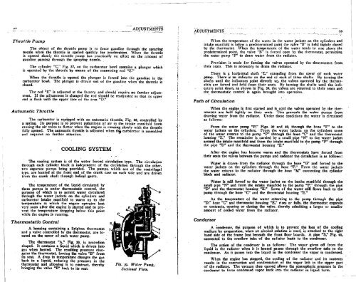
A housing containing a Sylphon thermostat<br />
and a valve controlled by the thermostat, are located<br />
on the cover of each water pump.<br />
The thermostat "A," Fig. 39, is accordion<br />
shaped. It contains a liquid which is driven into<br />
gas when heated. The resulting pressure elongates<br />
the thermostat, forcing the valve "B" from<br />
its seat. A drop in temperature changes the gas<br />
back to a liquid, reducing the pressure in the<br />
thermostat and allowing it to contract, thereby<br />
bringing the valve "B" back to its seat.<br />
Fig. 39. Water Pump,<br />
Sectional View.<br />
ADJUSTMENTS 55<br />
Path of<br />
When the temperature of the water in the water jackets on the cylinders and<br />
intake manifold is below a predetermined point the valve "B" is held tightly closed<br />
by the thermostat. When the temperature of the water tends to rise above the<br />
predetermined point, the valve "B" is forced open by the thermostat, permitting<br />
the water pump "P" to draw water from the radiator.<br />
Provision is made for forcing the valves operated by the thermostats from<br />
their seats. This is necessary to drain the radiator.<br />
There is a horizontal shaft "L" extending from the cover of each water<br />
pump. There is an indicator on the end of each of these shafts. By turning the<br />
shafts until the indicators point directly up, the valves operated by the thermostats<br />
are forced and held from their seats. By turning the shafts until the indicators<br />
point down, as shown in Fig. 39. the valves are returned to their seats and<br />
the thermostatic control is again brought into operation.<br />
Circulation<br />
When the engine is first started and is cold the valves operated by the thermostats<br />
are held tightly on their seats. This prevents the water pumps from<br />
drawing water from the radiator. Under these conditions the water is circulated<br />
as follows:<br />
From the water pump "P," Figs. 39 and 40, through the hose "F" to the<br />
water jackets on the cylinders. From the water jackets on the cylinders some<br />
of the water returns to the pump "P" through the hose "C" and the thermostat<br />
housing "E." The remainder is carried by a small pipe "N" to the water jacket<br />
around the intake manifold and from the intake manifold to the pump "P" through<br />
the pipe "D" and the thermostat housing "E."<br />
After the engine has become warm and the thermostats have forced from<br />
their seats the valves between the pumps and radiator the circulation is as follows:<br />
Water is drawn- from the radiator through the hose "G" and forced to the<br />
water jackets on the cylinders through the hose "F." From the water jackets<br />
the water returns to the radiator through the hose "M" connecting the cylinder<br />
block and radiator.<br />
Water is still forced to the water jacket on the intake manifold through the<br />
small pipe "N" and from the intake manifold to the pump "P." through the pipe<br />
"D" and the thermostat housing "E." Some of the water still flows back to the<br />
pump through the hose "C" and the thermostat housing "E."<br />
As the temperature of the water returning to the pump through the pipe<br />
"D," hose "C" and thermostat housing "E," rises or falls, the thermostat expands<br />
or contracts, opening or closing the valve, thereby admitting a larger or smaller<br />
amount of cooled water from the radiator.<br />
Condenser<br />
A condenser, the purpose of which is to prevent the loss of the cooling<br />
medium by evaporation, when an alcohol solution is used, is attached to the right<br />
hand side of the frame just beneath the front floor boards. A pipe "S," Fig. 40,<br />
connected to the overflow tube of the radiator leads to the condenser.<br />
The action of the condenser is as follows: The vapor given off from the<br />
. liquid in the radiator when it is heated passes through the overflow tube to the<br />
condenser. As it passes into the liquid in the condenser the vapor is condensed.<br />
When the engine has stopped, the cooling of the radiator and its contents<br />
results in the contraction and condensation of the vapor left in the upper part<br />
of the radiator. The vacuum thus caused allows the atmospheric pressure in the<br />
condenser to force condensed vapor back into the radiator in liquid form.


