- Page 1 and 2:
*ffi:fe
- Page 3 and 4:
* • * , • - ; " : • • • P
- Page 5 and 6:
C A D I L L A C S T A N D A R D OF
- Page 7 and 8:
C A D I L L A C S T A N D A R D OF
- Page 9 and 10:
C A D I L L A ' C S T A N D A R D O
- Page 11 and 12:
C A D I L L A C S T A N D A R D OF
- Page 13:
Price List of Parts / M V C\!)II1\C
- Page 16 and 17:
TIRES, SPEEDOMETERS, CLOCKS AND STO
- Page 18 and 19:
Codeword Serial p,rt Name Synibol ?
- Page 20 and 21:
12 ' ENGINE ENGINE 13 Codeword Seri
- Page 22 and 23:
16 ENGINE 17 Codeword BAZAB CAZAB D
- Page 24 and 25:
20 ENGINE ENGINE 21 Code Won) BAKED
- Page 26 and 27:
24 ENGINE GENERATOR 25 Codeword BAR
- Page 28 and 29:
28 GENERATOR GENERATOR 29 Codeword
- Page 30 and 31:
32 DISTRIBUTOR RELAY 33 Codeword BA
- Page 32 and 33:
HORN 37 A-2I3S ^ A-2129 UL A-2128 U
- Page 34 and 35:
40 LIGHTING Codeword BABOM CABOM DA
- Page 36 and 37:
44 Codeword BAHOM CAHOM DAHOM FAHOM
- Page 38 and 39:
48 TIRE PUMP CodeWoid Serial Part N
- Page 40 and 41:
52 CLUTCH CLUTCH 53 Code Word BABUP
- Page 42 and 43:
56 RADIATOR GASOLINE SYSTEM ai Code
- Page 44 and 45:
60 FRAME FRAME 61 HAND AIR PRESSURE
- Page 46 and 47:
64 SPRINGS SPRINGS 65 -Codeword Ser
- Page 48 and 49:
SPRINGS Codeword Serial Part Hame S
- Page 50 and 51:
72 STEERING GEAR STEERING GEAR 73 S
- Page 52 and 53:
76 FENDERS Codeword BABAS CABAS DAB
- Page 54 and 55:
80 SPLASH SHIELDS Code Word Serial
- Page 56 and 57:
84 TOPS CURTAINS, CURTAIN RODS AND
- Page 58 and 59:
88 TOPS Codeword Serial Part Name S
- Page 60 and 61:
92 FRONT AXLE REAR AXLE 93 REAR AXL
- Page 62 and 63:
96 REAR AXLE REAR AXLE 97 Code Word
- Page 64 and 65:
100 REAR AXLE A-8059.^ A-8081 -^T~-
- Page 66 and 67:
104 WINDSHIELD RAIN STRIP AND RUBBE
- Page 68 and 69:
108 Codeword BADEL CADEL FADEL KADE
- Page 70 and 71:
112 CUSHIONS Codeword Serial CADES
- Page 72 and 73:
116 TOE BOARDS TOE BOARDS, MATS AND
- Page 74 and 75:
120 FOOT BOARDS AUXILIARY CHAIR 121
- Page 76 and 77:
124 A TABLE OF CONTENTS Alphabetica
- Page 78 and 79:
CADILLAC '-QTOH CARjTO. • ihop ma
- Page 80 and 81:
GENERAL DATA KN(ilKK: . Nur.il'cr o
- Page 82 and 83:
2. Valves not seating. DIAGNOSIS 12
- Page 84 and 85:
10 DIAGNOSIS (A. Air valve spring i
- Page 86 and 87:
14 COOLING SYSTEM DIAGNOSIS Additio
- Page 88 and 89:
18 DIAGNOSIS 2. Clogged copper pipe
- Page 90 and 91:
22 DIAGNOSIS 2. Unsuitable lubrican
- Page 92 and 93:
26 DIAGNOSIS Insufficient Flow of O
- Page 94 and 95:
30 ADJUSTMENTS The desired clearanc
- Page 96 and 97:
34 ADJUSTMENTS Bring the ends of th
- Page 98 and 99:
'S i a i l .ti i' !i. ii' ^ i •
- Page 100 and 101:
42 ADJUSTMENTS Cleaning Distributor
- Page 102 and 103:
46 ADJUSTMENTS ADJUSTMENTS 47 to ut
- Page 104 and 105:
50 ADJUSTMENTS from an ice plant. T
- Page 106 and 107:
54 ADJUSTM ENTS Do not use a soluti
- Page 108 and 109:
58 ADJUSTMENTS ADJUSTMENTS 59 Check
- Page 110 and 111:
«2 ADJUST MENT.S Throttle Pump The
- Page 112 and 113:
ADJUSTMENTS (57 bevel pinion "C" on
- Page 114 and 115:
70 HAND BRAKES (Internal Expanding)
- Page 116 and 117:
74 ADJUSTMENTS Do not tighten again
- Page 118 and 119:
; if. -;• >W •.Hi' PI IL Kli-J
- Page 120 and 121:
82 REMOVAL, INSPECTION AND REPLACEM
- Page 122 and 123:
86 REMOVAL, INSPECTION AND REPLACEM
- Page 124 and 125:
90 REMOVAL, INSPECTION AND REPLACEM
- Page 126 and 127:
94 REMOVAL. INSPECTION AND REPLACEM
- Page 128 and 129:
98 REMOVAL, INSPECTION AND REPLACEM
- Page 130 and 131:
102 REM OVAL, INSPECTION AND REPLAC
- Page 132 and 133:
106 REMOVAL, INSPECTION AND REPLACE
- Page 134 and 135:
110 REMOVAL, INSPECTION AND REPLACE
- Page 136 and 137:
1H REMOVAL, INSPECTION AND REPLACEM
- Page 138 and 139:
118 REMOVAL, INSPECTION AND REPLACE
- Page 140 and 141:
122 REMOVAL, INSPECTION AND REPLACE
- Page 142 and 143:
12C REMOVAL, INSPECJ-UJN,^0 R E P L
- Page 144 and 145:
130 REMOVAL. INSPECTION AND REPLACE
- Page 146 and 147:
^^^JKSV^IO*^^ Inspection Clean all
- Page 148 and 149:
- 8 REMOVAL. INSPECTION AND REPLACE
- Page 150 and 151:
142 REMOVAL, INSPECTION AND REPLACE
- Page 152 and 153:
146 REMOVAL, INSPECTION AND REPLACE
- Page 154 and 155:
150 REMOVAL, INSPECTION AND REPLACE
- Page 156 and 157:
154 REMOVAL, INSPECTION AND REPLACE
- Page 158 and 159:
158 REMOVAL, INSPECTION AND REPLACE
- Page 160 and 161:
162 REMOVAL, INSPECTION AND REPLACE
- Page 162 and 163:
166 REMOVAL, INSPECTION AND REPLACE
- Page 164 and 165:
170 REMOVAL, INSPECTION AND REPLACE
- Page 166 and 167:
LUBRICATION 175 PART IV LUBRICATION
- Page 168 and 169:
178 LUBRICATION tained, after forci
- Page 170 and 171:
w LUBEIiCATlON n i ?! 1 U I! 35 f
- Page 172 and 173:
INDEX—Continued Page Cover plate
- Page 174 and 175:
Inspection—Continued INDEX—Cont
- Page 176 and 177:
Replacement—Continued IND E X—C
- Page 178 and 179:
Emht 1' -->« MANUAL/ #f
- Page 180 and 181:
; /- Type 57 MANUAL of CARE AND OPE
- Page 182 and 183:
INDEX INDEX 5 Draining Cooling Syst
- Page 184 and 185:
8 OPERATION AND GENERAL CARE OPERAT
- Page 186 and 187:
12 OPERATION AND GENERAL CARE OPERA
- Page 188 and 189:
16 OPERATION AND GENERAL CARE OPERA
- Page 190 and 191:
20 OPERATION AND GENERAL CARE Foldi
- Page 192 and 193:
24 OPERATION AND GENERAL CARE OPERA
- Page 194 and 195:
OPERATION AND GENERAL CARE OPERATIO
- Page 196 and 197:
33 OPERATION AND GENERAL CARE Posit
- Page 198 and 199:
36 LUBRICATION LUBRICATION 3T LUBRI
- Page 200 and 201:
40 LUBRICATION Replace Oil in Engin
- Page 202 and 203:
44 LUBRICATION LUBRICATION 45 Oil C
- Page 204 and 205:
Part III i * ADJUSTMENTS i
- Page 206 and 207:
Method of Adjustment ADJUSTMENTS Op
- Page 208 and 209:
56 ADJUSTMENTS The proper operation
- Page 210:
60 ADJUSTMENTS ADJUSTMENTS 61 Befor
- Page 213 and 214:
ADJUSTMENTS 67 Motor When acting as
- Page 215 and 216:
70 ADJUSTMENTS ADJUSTMENTS 71 Clean
- Page 217 and 218:
74 ADJUSTMENTS ADJUSTMENTS 75 Timin
- Page 219 and 220:
78 ADJUSTMENTS Adding Water to Stor
- Page 221 and 222:
82 ADJUSTMENTS The battery should b
- Page 223 and 224:
86 ADJUSTMENTS ADJUSTMENTS 87 There
- Page 225 and 226:
90 ADJUSTMENTS General Construction
- Page 227 and 228:
94 ADJUSTMENTS ADJUSTMENTS 95 Adjus
- Page 229 and 230:
98 ADJUSTMENTS Spring Clips SPRINGS
- Page 231 and 232:
Type 57 t MANUAL of CARE AND OPERAT
- Page 233 and 234:
IXDEX IXDEX Draining Cooling System
- Page 235 and 236:
*_»* U1\4V^1V'> . 1-* 1-» VJA. >J
- Page 237 and 238:
OPERATION AND GENERAL. t-AKt OPERAT
- Page 239 and 240:
Automatic Spark Control When each p
- Page 241 and 242:
20 OPERATION AXD GENERAL CARE Foldi
- Page 243 and 244:
\JC ILIV.-V LIKJL* AAU Vjl^^CtV^LJ-
- Page 245 and 246:
28 OPERATION AND GENERAL CARE OPERA
- Page 247 and 248:
32 OPERATION AND GENERAL CARE Posit
- Page 249 and 250:
30 LUBRICATION LUBRICATION' 37 LUBR
- Page 251 and 252:
40 LUBRICATION Replace Oil in Engin
- Page 253 and 254:
44 LUBRICATION Oil Cups and Oil Hol
- Page 255 and 256:
Part III ADJUSTMENTS
- Page 257 and 258:
i. I'-'J ^» •-» A *»l.X-it* A
- Page 259 and 260: ADJUSTMENTS I ADJUSTMENTS , tl The
- Page 261 and 262: 60 ADJUSTMENTS Before replacing the
- Page 263 and 264: 04 ADJUSTMENTS ADJUSTMENTS G5 Rivet
- Page 265 and 266: ADJUSTMENTS 69 Tilting Head Lamp Re
- Page 267 and 268: Distributor and Timer ADJUSTMENTS T
- Page 269 and 270: .Airunefer Current GENERATION OF CU
- Page 271 and 272: 80 ADJUSTMENTS After removing the f
- Page 273 and 274: 84 ADJUSTMENTS Operation The transm
- Page 275 and 276: . 88 ADJUSTMENTS ADJUSTMENTS > ,8»
- Page 277 and 278: ADJUSTMENTS Rotate the wheel until
- Page 279 and 280: * • 96 ADJUSTMENTS ADJUSTMENTS .
- Page 282 and 283: i MANUAL of CARE AND OPERATION FOR
- Page 284 and 285: STARTING THE ENGINE OPERATION 1. Fi
- Page 286 and 287: AIR PRESSURE GAUGE SPARK LEVER THRO
- Page 288 and 289: 13 OPERATION OPERATION 13 Rules of
- Page 290 and 291: 16 OPERATION OPERATION 17 The curta
- Page 292 and 293: 20 OPERATION Using the Compressor T
- Page 294 and 295: 24 OPERATION Automatic Spark Contro
- Page 296 and 297: 28 LUBRICATION Lubricating System E
- Page 298 and 299: o < J! S VJ *• ^.s •5 8 "^5 °S
- Page 300 and 301: 36 LUBRICATION LUBRICATION 37 Wheel
- Page 302 and 303: 40 GENERAL CARE TIRES Each tire mak
- Page 304 and 305: 44 GENERAL CARE Engine STORAGE To p
- Page 306 and 307: 4S GENERAL CARE GENERAL CARE 4J Gen
- Page 308 and 309: 02 GENERAL CARE Cleaning Lamp Refle
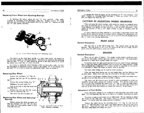
- Page 312 and 313: GEXERAL CARE Then adjust the nut "C
- Page 314 and 315: 04 REPAIR PARTS REPAIR PARTS Orderi
- Page 316 and 317: Index of all Cadillac Models using
- Page 318 and 319: INDEX OF ALL CADILLAC MODELS USING
- Page 320 and 321: 1 Cadillac Models Year Used Chart S
- Page 322 and 323: Motor Generator Page 2 THE DAYTON E
- Page 324 and 325: PIECE PARTS CATALOG Motor Generator
- Page 326 and 327: PIECE PARTS CATALOG Motor Generator
- Page 328 and 329: PIECE PARTS CATALOG Motor Generator
- Page 330 and 331: Motor Generator ^ p^yTON ENGINEERIN
- Page 332 and 333: 24 Motor Generator Page 4 THE DAYTO
- Page 334 and 335: 44 Motor Generator Page 2 THE DAYTO
- Page 336 and 337: 44 Motor Generator Page 4 THE DAYTO
- Page 338 and 339: p!r e r6 General ° r THE DAYTONENG
- Page 340 and 341: 78 Motor Generator PIECE PARTS CATA
- Page 342 and 343: 78 Motor Generator PIECE PARTS CATA
- Page 344 and 345: 78 Motor Generator PIECE PARTS CATA
- Page 346 and 347: 98 Motor Generator Page 2 THE DAYTO
- Page 348 and 349: 98 Motor Generator Page 4 THE DAYTO
- Page 350 and 351: PIECE PARTS CATALOG 162 Motor Gener
- Page 352 and 353: PIECE PARTS CATALOG 162 Motor Gener
- Page 354 and 355: PIECE PARTS CATALOG, Motor Generato
- Page 356 and 357: 1UUS» Ignition Switch PIECE PARTS
- Page 358 and 359: PIECE PARTS CATALOG 1035 Combinatio
- Page 360 and 361:
PIECE PARTS CATALOG Combination Swi
- Page 362 and 363:
1042 Combination Switch THE DAYTON
- Page 364 and 365:
PIECE PARTS CATALOG 1045 Combinatio
- Page 366 and 367:
1045 Combination Switch PIECE PARTS
- Page 368 and 369:
Horn Switch^ M ^ ^ E N f i ^ ^ No.
- Page 370 and 371:
PIECE PARTS CATALOG Battery Box Pag
- Page 373 and 374:
5311 Auto Horn Pane 2 THE DAYTON EN
- Page 375 and 376:
5310 Auto Horn Page 2 THE DAYTON EN
- Page 377:
Auto Horn Page 2 THE DAYTON ENGINEE
- Page 380 and 381:
Distributor Page 2 THE DAYTON ENGIN
- Page 382 and 383:
5166 Distributor Page 4 TTIK DAYTON
- Page 384 and 385:
5166 Distributor PIECE PARTS CATALO
- Page 386 and 387:
Distributor Page 2 THE DAYTON ENGIN
- Page 388 and 389:
5105 Distributor PIECE PARTS CATALO
- Page 390 and 391:
PIECE PARTS CATALOG Lnsti-iDutor Pa
- Page 392 and 393:
£1 10429 1 3 3 9 2 13394 13393 133
- Page 394 and 395:
SU55 Distributor Page 2 THE DAYTON
- Page 396 and 397:
5049 Distributor PIECE PARTS CATALO
- Page 398 and 399:
PIECE PARTS CATALOG 2115 Ignition C
- Page 400 and 401:
2093 Ignition Coil PIECE PARTS CATA
- Page 402 and 403:
PIECE PARTS CATALOG Ignition Coil P
- Page 404 and 405:
PIECE PARTS CATALOG Coil Box Page 1
- Page 406 and 407:
Ignition Switch Page 2 THE DAYTON E
- Page 408 and 409:
1978 Ignition Switch Page 2 THE DAY
- Page 410 and 411:
PIECE PARTS CATALOG 1150 Combinatio
- Page 412 and 413:
PIECE PARTS CATALOG Combination Swi
- Page 414 and 415:
1099 Combination Switch Page 2 THE
- Page 416 and 417:
PIECE PARTS CATALOG Combination 107
- Page 418 and 419:
13324 ft 12142 26527 26531 26544 »
- Page 420 and 421:
No. 1069 COMBINATION SWITCH Piece N
- Page 422 and 423:
PIECE PARTS CATALOG „ , 1062 Comb
- Page 424 and 425:
5401 Battery Box Page 2 THE DAYTON
- Page 426 and 427:
5401 Battery Page 4 Box THE DAYTON
- Page 428 and 429:
5401 Battery Box Pagel THE DAYTON E
- Page 430 and 431:
5401 Battery Box Page 8 THE DAYTON
- Page 432 and 433:
5401 Battery Box Page 10 THE DAYTON
- Page 434 and 435:
5401 Battery E Cage 12 Till': DAYTO
- Page 436 and 437:
No. 5404 BATTERY BOX
- Page 438 and 439:
5404 Battery Box PIECE PARTS CATALO
- Page 440 and 441:
5440 Clutch Magnet PIECE PARTS CATA
- Page 442 and 443:
5447 Clutch Magnet PIECE PARTS CATA
- Page 444 and 445:
5506 Apparatus Box Page 2 THE DAYTO
- Page 446 and 447:
B OS
- Page 448 and 449:
5677 Ignition Relay PIECE PARTS CAT
- Page 450 and 451:
No. 5692 CIRCUIT BREAKER
- Page 453:
5695 Circuit Breaker Page 2 THE DAY
- Page 456 and 457:
I J L J 12149 26297 24375 24485 249
- Page 458 and 459:
PIECE PARTS CATALOG 5742 Circuit Br
- Page 460 and 461:
10131 Terminal Board PIECE PARTS CA
- Page 462 and 463:
10686 7 Resistance Unit h PIKCB PAR
- Page 464:
11973 Motor Clutch PIECE PARTS CATA
- Page 468 and 469:
Cadillacs Eighteenth Year F I A HE
- Page 470 and 471:
C A D I L L A C S T A N D A R D OF
- Page 472 and 473:
C A D I L L A C S T A N D A R D OF
- Page 474 and 475:
C A D I L L A C S T A N D A R D OF
- Page 476 and 477:
CADILLAC COACH I N C E 1903 Cadilla
- Page 478 and 479:
C A D I L L A C S T A N D A R D OF
- Page 480 and 481:
C A D I L L A C S T A N D A R D OF
- Page 482 and 483:
C A D I L L A C S T A N D A R D OF
- Page 484 and 485:
C A D I L L A C S T A N D A R D T H
- Page 486 and 487:
C A D I L L A C S T A N D A R D OF