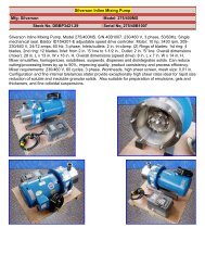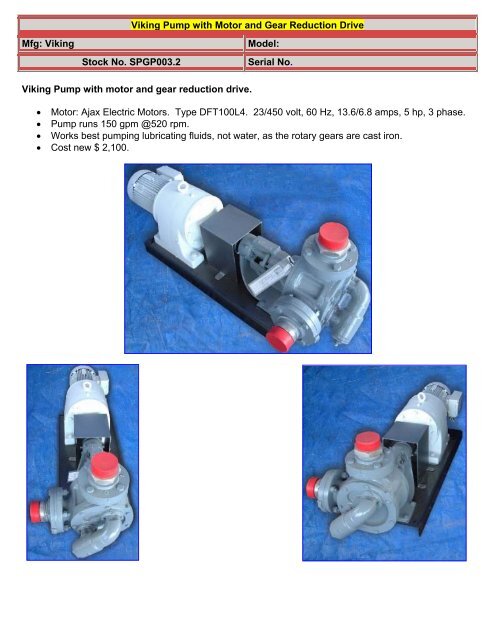
Viking Pump with Motor and Gear Reduction Drive - Genemco, Inc.
Viking Pump with Motor and Gear Reduction Drive - Genemco, Inc.
Viking Pump with Motor and Gear Reduction Drive - Genemco, Inc.

You also want an ePaper? Increase the reach of your titles
YUMPU automatically turns print PDFs into web optimized ePapers that Google loves.
<strong>Viking</strong> <strong>Pump</strong> <strong>with</strong> <strong>Motor</strong> <strong>and</strong> <strong>Gear</strong> <strong>Reduction</strong> <strong>Drive</strong><br />
Mfg: <strong>Viking</strong><br />
Model:<br />
Stock No. SPGP003.2<br />
Serial No.<br />
<strong>Viking</strong> <strong>Pump</strong> <strong>with</strong> motor <strong>and</strong> gear reduction drive.<br />
• <strong>Motor</strong>: Ajax Electric <strong>Motor</strong>s. Type DFT100L4. 23/450 volt, 60 Hz, 13.6/6.8 amps, 5 hp, 3 phase.<br />
• <strong>Pump</strong> runs 150 gpm @520 rpm.<br />
• Works best pumping lubricating fluids, not water, as the rotary gears are cast iron.<br />
• Cost new $ 2,100.
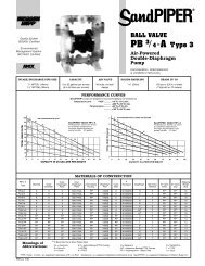
TECHNICAL SERVICE MANUAL<br />
HEAVY-DUTY BRACKET MOUNTED PUMPS<br />
SERIES 125 <strong>and</strong> 4125<br />
SIZES G-LL<br />
SECTION TSM 141.1<br />
PAGE 1<br />
ISSUE C<br />
CONTENTS<br />
Special Information 2<br />
Maintenance 2<br />
Packed <strong>Pump</strong>s 3<br />
Mechanical Seal <strong>Pump</strong>s<br />
St<strong>and</strong>ard Rubber Bellows Type<br />
(Sizes G, H, HL, K, KK, L, LQ & LL) 6<br />
Optional Teflon Seal 9<br />
St<strong>and</strong>ard Rubber Bellows Type<br />
(Sizes AK&AL) 11<br />
Thrust Bearing Adjustment 13<br />
Installation of Carbon Graphite Bushings 13<br />
Pressure Relief Valve Instructions 14<br />
FIGURE 1<br />
Sizes G, H <strong>and</strong> HL<br />
INTRODUCTION<br />
The illustrations used in this manual are for identification<br />
purposes only <strong>and</strong> cannot be used for ordering parts. Obtain<br />
a parts list from the factory or a <strong>Viking</strong>® representative.<br />
Always give complete name of part, part number <strong>and</strong><br />
material <strong>with</strong> model number <strong>and</strong> serial number of pump<br />
when ordering repair parts. The unmounted pump or pump<br />
unit model number <strong>and</strong> serial number are on the nameplate.<br />
In the <strong>Viking</strong> model number system, basic size letters are<br />
combined <strong>with</strong> series number (125 <strong>and</strong> 4125) indicating both<br />
unmounted or mounted pump unit.<br />
FIGURE 2<br />
Sizes AK <strong>and</strong> AL<br />
UNMOUNTED PUMP<br />
PACKED<br />
G125<br />
H125<br />
HL125<br />
AK125<br />
AL125<br />
MECH. SEAL<br />
G4125<br />
H4125<br />
HL4125<br />
AK4125<br />
AL4125<br />
UNITS<br />
Units are designed by the<br />
unmounted pump model<br />
numbers followed by a letter<br />
indicating drive style.<br />
K125 K4125 V=V-belt<br />
KK125 KK4125 D=Direct Connected<br />
L125 L4125 R=<strong>Viking</strong> Speed Reducer<br />
LQ125 LQ4125 P=Commercial Speed Reducer<br />
LL125<br />
LL4125<br />
FIGURE 3<br />
Sizes K. KK <strong>and</strong> LL<br />
This manual deals only <strong>with</strong> Series 125 <strong>and</strong> 4125 HeavyDuty<br />
Bracket Mounted <strong>Pump</strong>s. Refer to Figures 1 thru 19 for<br />
general configuration <strong>and</strong> nomenclature used in this manual.<br />
<strong>Pump</strong> specifications <strong>and</strong> recommendations are listed in<br />
Catalog Section 141, Series 125 <strong>and</strong> 4125 HeavyDuty<br />
Bracket Mounted <strong>Pump</strong>s.<br />
VIKING PUMP INC. •<br />
A Unit of IDEX Corporation •<br />
FIGURE 4<br />
Sizes LQ <strong>and</strong> LL
SPECIAL INFORMATION<br />
DANGER<br />
BEFORE OPENING ANY VIKING PUMP LIQUID<br />
CHAMBER (PUMPING CHAMBER, RESERVOIR,<br />
RELIEF VALVE ADJUSTING CAP FITTING ETC.)<br />
BE SURE:<br />
1. THAT ANY PRESSURE IN CHAMBER HAS<br />
BEEN COMPLETELY VENTED THROUGH<br />
SUCTION OR DISCHARGE LINES OR<br />
OTHER APPROPRIATE OPENINGS OR<br />
CONNECTIONS.<br />
2. THAT THE DRIVING MEANS (MOTOR,<br />
TURBINE, ENGINE, ETC.) HAS BEEN<br />
“LOCKED OUT” OR MADE NON-<br />
OPERATIONAL SO THAT IT CANNOT BE<br />
STARTED WHILE WORK IS BEING DONE<br />
ON PUMP.<br />
3. THAT YOU KNOW WHAT LIQUID THE PUMP<br />
HAS BEEN HAN DLING AND THE<br />
PRECAUTIONS NECESSARY TO SAFELY<br />
HANDLE THE LIQUID. OBTAIN A MATERIAL<br />
SAFETY DATA SHEET (MSDS) FOR THE<br />
LIQUID TO BE SURE THESE PRECAUTIONS<br />
ARE UNDERSTOOD.<br />
FAILURE TO FOLLOW ABOVE LISTED<br />
PRECAUTIONARY MEASURES MAY RESULT IN<br />
SERIOUS INJURY OR DEATH.<br />
ROTATION: <strong>Viking</strong> pumps operate equally well in a<br />
clockwise or counterclockwise rotation. Shaft rotation<br />
determines which port is suction <strong>and</strong> which is discharge. Port<br />
in area where pumping elements (gear teeth) come out of<br />
mesh is suction port.<br />
PRESSURE RELIEF VALVES:<br />
1. <strong>Viking</strong> pumps are positive displacement pumps <strong>and</strong> must<br />
be provided <strong>with</strong> some sort of pressure protection. This<br />
may be a relief valve mounted directly on the pump, an<br />
inline pressure relief valve, a torque limiting device or a<br />
rupture disk.<br />
2. There are relief valve options available on those pump<br />
models designed to accept a relief valve. Options may<br />
include a return to tank relief valve <strong>and</strong> a jacketed relief<br />
valve. <strong>Pump</strong>s equipped <strong>with</strong> a jacketed head plate are<br />
generally not available <strong>with</strong> a relief valve.<br />
3. If pump rotation is reversed during operation, pressure<br />
protection must be provided on both sides of pump.<br />
4. Relief valve adjusting screw cap must always point<br />
towards suction side of pump. If pump rotation is<br />
reversed, remove pressure relief valve <strong>and</strong> turn end for<br />
end. Refer to Figures 1, 2, 3 <strong>and</strong> 4.<br />
5. Pressure relief valves cannot be used to control pump<br />
flow or regulate discharge pressure.<br />
For additional information on pressure relief valves, refer to<br />
Technical Service Manual TSM000 <strong>and</strong> Engineering Service<br />
Bulletin ESB-31.<br />
SPECIAL INFORMATION<br />
SPECIAL MECHANICAL SEALS can be installed either<br />
next to rotor hub or in an altered stuffing box.<br />
Extra care must be taken in repair of pumps <strong>with</strong> mechanical<br />
seals. Read <strong>and</strong> follow all special information supplied <strong>with</strong><br />
pump.<br />
MAINTENANCE<br />
Series 125 <strong>and</strong> 4125 pumps are designed for long, troublefree<br />
service life under a wide variety of application conditions<br />
<strong>with</strong> a minimum of maintenance. The points listed below will<br />
help provide long service life.<br />
LUBRICATION: External lubrication must be applied slowly<br />
<strong>with</strong> a h<strong>and</strong> gun to all lubrication fittings every 500 hours of<br />
operation <strong>with</strong> multi-purpose grease, NLGI #2. Do not overgrease.<br />
Applications involving very high or low temperatures<br />
will require other types of lubrication. Refer to Engineering<br />
Service Bulletin ESB-515. Consult factory <strong>with</strong> specific<br />
lubrication questions.<br />
PACKING ADJUSTMENT: New packed pumps require initial<br />
packing adjustment to control leakage as packing ‘runs in”.<br />
Make initial adjustments carefully <strong>and</strong> do not over-tighten<br />
packing gl<strong>and</strong>. After initial adjustment, inspection will reveal<br />
need for packing gl<strong>and</strong> adjustment or packing replacement.<br />
Refer to instructions under Disassembly, page 4, <strong>and</strong><br />
Assembly, page 4, regarding repacking pump.<br />
CLEANING PUMP: Keep pump as clean as possible. This<br />
will facilitate inspection, adjustment <strong>and</strong> repair work <strong>and</strong> help<br />
prevent overlooking a dirt covered grease fitting.<br />
STORAGE: If pump is to be stored, or not used for six<br />
months or more, pump must be drained <strong>and</strong> a light coat of<br />
non-detergent SAE 30 weight oil must be applied to all<br />
internal pump parts. Lubricate fittings <strong>and</strong> apply grease to<br />
pump shaft extension. <strong>Viking</strong> suggests rotating pump shaft<br />
by h<strong>and</strong> one complete revolution every 30 days to circulate<br />
the oil.<br />
SUGGESTED REPAIR TOOLS: The following tools must be<br />
available to properly repair Series 125 <strong>and</strong> 4125 pumps.<br />
These tools are in addition to st<strong>and</strong>ard mechanics’ tools such<br />
as open end wrenches, pliers, screw drivers, etc. Most of the<br />
items can be obtained from an industrial supply house.<br />
1. Soft Headed hammer<br />
2. AlIen wrenches (some mechanical seals <strong>and</strong> set collars)<br />
3. Packing hooks, flexible (packed pumps)<br />
Small for 0.25 inch <strong>and</strong> 0.31 inch cross section packing<br />
Large for 0.38 inch <strong>and</strong> up cross section packing<br />
4. Mechanical seal installation sleeve<br />
<strong>Viking</strong> Part No. 2-751-001-900 for 0.75 inch seal; G4125<br />
<strong>Viking</strong> Part No. 2-751-002-900 for 1.12 inch seal;<br />
H &HL4125<br />
<strong>Viking</strong> Part No. 2-751-003-900 for 1.44 inch seal;<br />
AK - LL4 125<br />
5. Bearing locknut spanner wrench<br />
(Source: #471 J. H. Williams & Co. or equal)<br />
6. Spanner wrench, adjustable pin type for use on double<br />
end caps (Source: #482 J. H. Williams & Co. or equal)<br />
7. Brass bar<br />
8. Arbor press<br />
2
PACKED PUMPS<br />
IDLER<br />
CASING<br />
BALL BEARING<br />
LIP SEAL OUTER<br />
END CAP<br />
PACKING GLAND<br />
BRACKET BUSHING<br />
PACKING RINGS<br />
ROTOR<br />
HEAD<br />
IDLER PIN<br />
VALVE BODY<br />
POPPET<br />
SHAFT<br />
VALVE SPRING<br />
SPRING GUIDE<br />
LOCKNUT<br />
BONNET<br />
OUTER END CAP<br />
LOCKNUT<br />
INNER END CAP<br />
LIP SEAL INNER END CAP<br />
BRACKET<br />
HEAD<br />
GASKET<br />
ADJUSTING<br />
SCREW<br />
PACKING RETAINING WASHER<br />
BRACKET GASKET<br />
PIPE PLUG<br />
VALVE GASKET<br />
VALVE CAP<br />
FIGURE 5<br />
Cutaway View of G 125 <strong>with</strong> Callouts<br />
Exploded View of Models G125, H125, HL125, AK125, Al 125, K125,<br />
KK125, L125, LQ125, <strong>and</strong> LL125 (Model KK125 shown)<br />
ITEM NAME OF PART ITEM NAME OF PART ITEM NAME OF PART ITEM NAME OF PART<br />
1 Locknut 10 Packing Gl<strong>and</strong> 19 Bracket Gasket 28 Gasket for Jacketed Head Pl ate<br />
2 Lockwasher (Not G) 11 Packing Gl<strong>and</strong> Nut 20 Casing 29 Jacketed Head Plate<br />
3 End Cap (Outer) 12 Packing Gl<strong>and</strong> Capscrew 21 Pipe Plug 30 Capscrew for Head<br />
4 Lip Seal for End Cap 13 Packing 22 Rotor <strong>and</strong> Shaft 31 Relief Valve Gasket<br />
5 Bearing Spacer Collar (Outer) 14 Packing Retaining Washer 23 Idler <strong>and</strong> Bushing 32 Capscrew for Valve<br />
6 Ball Bearing 15 Bracket Bushing 24 Idler Bushing 33 Internal Relief Valve<br />
7 Bearing Spacer Collar (Inner) 16 Grease Fitting 25 Head Gasket<br />
8 Ring, Half Round (Not G,H,HL) 17 Bracket <strong>and</strong> Bushing 26 Idler Pin<br />
9 End Cap (Inner) 18 Capscrew for Bracket 27 Head <strong>and</strong> Idler Pin<br />
3
DISASSEMBLY<br />
DANGER<br />
BEFORE OPENING ANY VIKING PUMP LIQUID<br />
CHAMBER (PUMPING CHAMBER, RESERVOIR,<br />
RELIEF VALVE ADJUSTING CAP FITTING ETC.)<br />
BE SURE:<br />
6. Carefully remove rotor <strong>and</strong> shaft to avoid damaging<br />
bracket bushing.<br />
7. Remove packing gl<strong>and</strong> from side of bracket.<br />
GREASE FITTING LOCATION<br />
1. THAT ANY PRESSURE IN CHAMBER HAS<br />
BEEN COMPLETELY VENTED THROUGH<br />
SUCTION OR DISCHARGE LINES OR<br />
OTHER APPROPRIATE OPENINGS OR<br />
CONNECTIONS.<br />
2. THAT THE DRIVING MEANS (MOTOR,<br />
TURBINE, ENGINE, ETC.) HAS BEEN<br />
“LOCKED OUT” OR MADE NON-<br />
OPERATIONAL SO THAT IT CANNOT BE<br />
STARTED WHILE WORK IS BEING DONE<br />
ON PUMP.<br />
3. THAT YOU KNOW WHAT LIQUID THE PUMP<br />
HAS BEEN HANDLING AND THE<br />
PRECAUTIONS NECESSARY TO SAFELY<br />
HANDLE THE LIQUID. OBTAIN A MATERIAL<br />
SAFETY DATA SHEET (MSDS) FOR THE<br />
LIQUID TO BE SURE THESE PRECAUTIONS<br />
ARE UNDERSTOOD.<br />
NYLON INSET<br />
INNER<br />
END CAP<br />
HALF ROUND<br />
RINGS<br />
INNER<br />
SPACER<br />
COLLAR<br />
INNER LIP SEAL<br />
BALL<br />
BEARING<br />
SETSCREWS<br />
BRACKET<br />
OUTER END CAP<br />
LOCKWASHER<br />
LOCKNUT<br />
OUTER LIP<br />
SEAL<br />
OUTER<br />
SPACER<br />
COLLAR<br />
FAILURE TO FOLLOW ABOVE LISTED<br />
PRECAUTIONARY MEASURES MAY RESULT IN<br />
SERIOUS INJURY OR DEATH.<br />
1. Mark head <strong>and</strong> casing before disassembly to insure<br />
proper reassembly. The idler pin, which is offset in pump<br />
head, must be positioned toward <strong>and</strong> equal distance<br />
between port connections to allow for proper flow of liquid<br />
through pump.<br />
Remove head from pump. Do not allow idler to fall from<br />
idler pin. Tilt top of head back when removing to prevent<br />
this. Avoid damaging head gasket. If pump is furnished<br />
<strong>with</strong> pressure relief valve, it need not be removed from<br />
head or disassembled at this point. Refer to Pressure<br />
Relief Valve Instructions, page 14.<br />
If pump has jacketed head plate, it will separate from<br />
head when it is removed. The gasket between head <strong>and</strong><br />
jacket head plate must be totally removed. Use new<br />
gasket when assembling pump.<br />
2. Remove idler <strong>and</strong> bushing assembly.<br />
3. Insert length of hardwood or brass through port opening<br />
between rotor teeth to keep shaft from turning. Bend up<br />
tang of lockwasher <strong>and</strong> <strong>with</strong> a spanner wrench remove<br />
locknut <strong>and</strong> lockwasher from shaft. There is no<br />
lockwasher on G size pump.<br />
4. Remove packing gl<strong>and</strong> nuts.<br />
5. Tap shaft forward approximately 0.5 inch <strong>and</strong> remove pair<br />
of half round rings under inner bearing spacer collar.<br />
There is no pair of half round rings on G, H <strong>and</strong> HL size<br />
pumps.<br />
8. Loosen setscrews. Two on G, H <strong>and</strong> HL size pumps,<br />
four on all other sizes. With a spanner wrench, remove<br />
both end caps <strong>with</strong> lip seals. Remove ball bearing <strong>and</strong><br />
spacer collars. Refer to Figure 6.<br />
9. Remove packing <strong>and</strong> packing retainer washer.<br />
10. Clean all parts thoroughly <strong>and</strong> examine for wear <strong>and</strong><br />
damage. Check lip seals, ball bearing, bushings <strong>and</strong><br />
idler pin <strong>and</strong> replace if necessary. Check all other parts<br />
for nicks, burrs, excessive wear <strong>and</strong> replace if<br />
necessary.<br />
Wash bearings in clean solvent. Blow out bearings <strong>with</strong><br />
compressed air. Do not allow bearings to spin; turn them<br />
slowly by h<strong>and</strong>. Spinning bearings will damage race <strong>and</strong><br />
balls. Make sure bearings are clean, then lubricate <strong>with</strong><br />
non-detergent SAE 30 weight oil <strong>and</strong> check for<br />
roughness. Roughness can be determined by turning<br />
outer race by h<strong>and</strong>.<br />
11. Casing can be checked for wear or damage while<br />
mounted on bracket.<br />
ASSEMBLY<br />
FIGURE 6<br />
1. Install bracket bushing. If bracket bushing has a<br />
lubrication groove, install bushing <strong>with</strong> groove at 6:00<br />
o’clock position in bracket. If carbon graphite, refer to<br />
Installation of Carbon Graphite Bushings, page 13.<br />
2. Coat shaft of rotor shaft assembly <strong>with</strong> non-detergent<br />
SAE 30 weight oil. Start end of shaft in bracket bushing<br />
turning from right to left, slowly pushing rotor in casing.<br />
4
3. Place packing retainer washer in bottom of packing<br />
chamber <strong>and</strong> pack pump <strong>with</strong> new packing. Use packing<br />
suitable for liquid being pumped. Install packing,<br />
staggering the joints from one side of shaft to other.<br />
Lubricate packing rings <strong>with</strong> oil, grease or graphite to aid<br />
assembly. A length of pipe will help to seat each packing<br />
ring.<br />
4. Install packing gl<strong>and</strong>, capscrews <strong>and</strong> nuts. Back rotor<br />
<strong>and</strong> shaft out of casing just far enough to ins ert packing<br />
gl<strong>and</strong> through side opening of bracket over end of shaft.<br />
Make sure gl<strong>and</strong> is installed square <strong>and</strong> nuts are<br />
tightened evenly. Tighten nuts wrench tight then back off<br />
until gl<strong>and</strong> is slightly loose.<br />
5. Coat idler pin <strong>with</strong> non-detergent SAE 30 weight oil <strong>and</strong><br />
place idler <strong>and</strong> bushing on idler pin in head. If replacing<br />
<strong>with</strong> carbon graphite bushing, refer to Installation of<br />
Carbon Graphite Bushings, page 13.<br />
6. Using a .010 to .015 inch head gasket, install head <strong>and</strong><br />
idler assembly on pump. <strong>Pump</strong> head <strong>and</strong> casing were<br />
marked before disassembly to insure proper reassembly.<br />
If not, be sure idler pin, which is offset in pump head, is<br />
positioned toward <strong>and</strong> equal distance between port<br />
connections to allow for proper flow of liquid through<br />
pump.<br />
If pump is equipped <strong>with</strong> jacketed head plate, install at<br />
this time along <strong>with</strong> new gasket.<br />
Tighten head capscrews evenly.<br />
7. Slide inner spacer collar over shaft <strong>with</strong> recessed end<br />
facing rotor. G, H <strong>and</strong> HL size bearing spacer collars are<br />
not recessed.<br />
Place pair of half round rings on shaft <strong>and</strong> slide inner<br />
bearing spacer collar over half round rings to lock them<br />
in place. There is no pair of half round rings on G, H <strong>and</strong><br />
HL size pumps. Refer to Figure 6, page 4.<br />
8. Press lip seal, lip facing end of shaft, in inner end cap<br />
<strong>and</strong> insert end cap through shaft end of bracket. Turn<br />
end cap clockwise, looking at shaft end, until it engages<br />
threads. End cap spanner wrench holes must be facing<br />
rotor. Turn end cap <strong>with</strong> spanner wrench until it projects<br />
slightly from opening on side of bracket. End cap must<br />
not be turned so far that lip seal drops off end of spacer<br />
collar on shaft or end cap becomes disengaged from<br />
threads. Refer to Figure 6, page 4.<br />
If this happens, remove inner spacer collar, half round<br />
rings <strong>and</strong> end cap <strong>and</strong> start over at Step 7.<br />
9. Pack ball bearing <strong>with</strong> multi-purpose grease, NLGI #2.<br />
Place on shaft <strong>and</strong> push or gently drive in place in<br />
bracket.<br />
10. Press lip seal, lip facing end of shaft, in outer end cap<br />
<strong>and</strong> insert end cap in bracket. Turn end cap in bracket<br />
until it is tight against bearing. Refer to Figure 6, page 4.<br />
11. Put Iockwasher <strong>and</strong> locknut on shaft. Insert length of<br />
hardwood or brass through port opening between rotor<br />
teeth to keep shaft from turning. Tighten locknut <strong>and</strong><br />
bend one tang of lockwasher into slot of locknut. There is<br />
no lockwasher on G size pumps.<br />
12. Adjust pump end clearance. Refer to Thrust Bearing<br />
Adjustment, page 13.<br />
13. Lubricate all grease fittings <strong>with</strong> multi-purpose grease,<br />
NLGI #2.<br />
DANGER<br />
BEFORE STARTING PUMP, BE SURE ALL DRIVE<br />
EQUIPMENT GUARDS ARE IN PLACE.<br />
FAILURE TO PROPERLY MOUNT GUARDS MAY<br />
RESULT IN SERIOUS INJURY OR DEATH.<br />
5
MECHANICAL SEAL PUMPS<br />
INNER END CAP<br />
LIP SEAL INNER END CAP<br />
MECHANICAL SEAL<br />
BRACKET BUSHING<br />
CASING<br />
ROTOR<br />
SHAFT<br />
IDLER<br />
OUTER END CAP<br />
IDLER PIN<br />
LOCKNUT<br />
VALVE BODY<br />
POPPET<br />
LOCKWASHER<br />
LIP SEAL OUTER<br />
END CAP<br />
VALVE SPRING<br />
BONNET GASKET<br />
BALL BEARING<br />
SPRING GUIDE<br />
SETSCREW<br />
BONNET<br />
LIPSEAL<br />
PIPE PLUG<br />
HEAD GASKET<br />
HEAD<br />
CAP GASKET<br />
VALVE GASKET<br />
BRACKET<br />
GREASE FITTING<br />
BRACKET GASKET<br />
LOCKNUT<br />
ADJUSTING SCREW<br />
FIGURE 7<br />
Cutaway View of KK 4125 <strong>with</strong> Callouts<br />
VALVE CAP<br />
Exploded View for Models G4125, H4125, HL4125, K4125, KK4125,<br />
L4125, LQ4125 <strong>and</strong> LL4125 (Model KK4125 shown)<br />
ITEM NAME OF PART ITEM NAME OF PART ITEM NAME OF PART ITEM NAME OF PART<br />
1 Locknut 9 End Cap (Inner) 17 Bracket Gasket 25 Head <strong>and</strong> Idler Pin<br />
2 Lockwasher (Not G) 10 Lip Seal for Seal Chamber 18 Casing 26 Gasket for Jacketed Head Plate<br />
3 End Cap (Outer) 11 Pressure Relief Plug 19 Pipe Plug 27 Jacketed Head Plate<br />
4 Lip Seal for End Cap 12 Grease Fitting 20 Rotor <strong>and</strong> Shaft 28 Capscrew for Head<br />
5 Bearing Spacer Collar (Outer) 13 Bracket <strong>and</strong> Bushing 21 Idler <strong>and</strong> Bushing 29 Relief Valve Gasket<br />
6 Ball Bearing 14 Capscrew for Bracket 22 Idler Bushing 30 Capscrew for Valve<br />
7 Bearing Spacer Collar (Inner) 15 Bracket Bushing 23 Head Gasket 31 Internal Relief Valve<br />
8 Ring, Half Round (Not G,H,HL) 16 Mechanical Seal 24 Idler Pin<br />
For Disassembly <strong>and</strong> Assembly of AK 4125 <strong>and</strong> AL 4125 see page 11.<br />
6
DISASSEMBLY<br />
DANGER<br />
BEFORE OPENING ANY VIKING PUMP LIQUID<br />
CHAMBER (PUMPING CHAMBER, RESERVOIR,<br />
RELIEF VALVE ADJUSTING CAP FITTING ETC.)<br />
BE SURE:<br />
1. THAT ANY PRESSURE IN CHAMBER HAS<br />
BEEN COMPLETELY VENTED THROUGH<br />
SUCTION OR DISCHARGE LINES OR<br />
OTHER APPROPRIATE OPENINGS OR<br />
CONNECTIONS.<br />
2. THAT THE DRIVING MEANS (MOTOR,<br />
TURBINE, ENGINE, ETC.) HAS BEEN<br />
“LOCKED OUT” OR MADE NON-<br />
OPERATIONAL SO THAT IT CANNOT BE<br />
STARTED WHILE WORK IS BEING DONE<br />
ON PUMP.<br />
3. THAT YOU KNOW WHAT LIQUID THE PUMP<br />
HAS BEEN HANDLING AND THE<br />
PRECAUTIONS NECESSARY TO SAFELY<br />
HANDLE THE LIQUID. OBTAIN A MATERIAL<br />
SAFETY DATA SHEET (MSDS) FOR THE<br />
LIQUID TO BE SURE THESE PRECAUTIONS<br />
ARE UNDERSTOOD.<br />
FAILURE TO FOLLOW ABOVE LISTED<br />
PRECAUTIONARY MEASURES MAY RESULT IN<br />
SERIOUS INJURY OR DEATH.<br />
1. Mark head <strong>and</strong> casing before disassembly to insure<br />
proper reassembly. The idler pin, which is offset in pump<br />
head, must be positioned toward <strong>and</strong> equal distance<br />
between port connections to allow for proper flow of liquid<br />
through pump.<br />
Remove head from pump. Do not allow idler to fall from<br />
idler pin. Tilt top of head back when removing to prevent<br />
this. Avoid damaging head gasket. If pump is furnished<br />
<strong>with</strong> pressure relief valve, it need not be removed from<br />
head or disassembled at this point. Refer to Pressure<br />
Relief Valve Instructions, page<br />
If pump has jacketed head plate, it will separate from<br />
head when it is removed. The gasket between head <strong>and</strong><br />
jacket head plate must be totally removed. Use new<br />
gasket when assembling pump.<br />
2. Remove idler <strong>and</strong> bushing assembly.<br />
3. Insert length of hardwood or brass through port opening<br />
between rotor teeth to keep shaft from turning. Bend up<br />
tang of Iockwasher <strong>and</strong> <strong>with</strong> a spanner wrench remove<br />
locknut <strong>and</strong> lockwasher from shaft. There is no<br />
lockwasher on G size pump.<br />
4. Tap shaft forward approximately 0.5 inch <strong>and</strong> remove pair<br />
of half round rings under inner spacer collar. There is no<br />
pair of half round rings on G, H <strong>and</strong> HL size pumps.<br />
5. Carefully remove rotor <strong>and</strong> shaft to avoid damaging<br />
bracket bushing.<br />
6. Remove rotary member of seal from shaft <strong>and</strong> stationary<br />
seal seat from bracket.<br />
7<br />
7. Loosen setscrews. Two for G, H <strong>and</strong> HL size pumps, four<br />
for all other sizes. With spanner wrench remove both end<br />
caps <strong>and</strong> lip seals. Remove ball bearing <strong>and</strong> spacer<br />
collars. Refer to Figure 6, page 4.<br />
8. Examine seal chamber lip seal <strong>and</strong> remove if it shows<br />
wear or damage. Lip seal must be removed if bracket<br />
bushing needs to be replaced.<br />
9. Clean all parts thoroughly <strong>and</strong> examine for wear or<br />
damage. Check lip seals, ball bearing, bushing <strong>and</strong> idler<br />
pin <strong>and</strong> replace if necessary. Check all other parts for<br />
nicks, burrs, excessive wear <strong>and</strong> replace if necessary.<br />
Wash bearings in clean solvent. Blow out bearings <strong>with</strong><br />
compressed air. Do not allow bearings to spin; turn them<br />
slowly by h<strong>and</strong>. Spinning bearings will damage race <strong>and</strong><br />
balls. Make sure bearings are clean, then lubricate <strong>with</strong><br />
non-detergent SAE 30 weight oil <strong>and</strong> check for<br />
roughness. Roughness can be determined by turning<br />
outer race by h<strong>and</strong>.<br />
Be sure shaft is free from nicks, burrs <strong>and</strong> foreign<br />
particles that might damage bracket bushing. Scratches<br />
on shaft in seal area will provide leakage paths under<br />
mechanical seal.<br />
10. Casing can be checked for wear or damage while<br />
mounted on bracket.<br />
ASSEMBLY<br />
St<strong>and</strong>ard Mechanical Seal<br />
(Synthetic Rubber Bellows Type)<br />
The seal used in this pump is simple to install <strong>and</strong> good<br />
performance will result if care is taken during installation.<br />
The principle of the mechanical seal is contact between the<br />
rotary <strong>and</strong> stationary members. These parts are lapped to a<br />
high finish <strong>and</strong> their sealing effectiveness depends on<br />
complete contact.<br />
<strong>Viking</strong> furnishes a number of heavy-duty pumps <strong>with</strong> special<br />
mechanical seals installed in the packing end of the pump.<br />
These special seals are not discussed in TSM141.1.<br />
Information is available by contacting the factory. When<br />
requesting special seal information, be sure to give pump<br />
model number <strong>and</strong> serial number.<br />
1. Install bracket bushing. If bracket bushing has a<br />
lubrication groove, install bushing <strong>with</strong> groove at 6:00<br />
o’clock position in bracket. If carbon graphite, refer to<br />
Installation of Carbon Graphite Bushings, page 13.<br />
2. Install lip seal in bracket. Refer to Figure 8.<br />
BRACKET<br />
BUSHING<br />
LIP SEAL FOR SEAL CHAMBER<br />
BRACKET<br />
FIGURE 8<br />
TAPERED<br />
INSTALLATION SLEEVE<br />
SHAFT
Prior to installing rotating portion of mechanical seal, prepare<br />
<strong>and</strong> organize rotor shaft, head <strong>and</strong> idler assemblies <strong>and</strong><br />
appropriate gaskets for quick assembly.<br />
Once rotating portion of mechanical seal is installed on rotor<br />
shaft, it is necessary to assemble parts as quickly as<br />
possible to insure that seal does not stick to shaft in wrong<br />
axial position. The seal should be expected to stick to the<br />
shaft after several minutes setting time.<br />
Never touch sealing faces <strong>with</strong> anything except clean h<strong>and</strong>s<br />
or clean cloth. Minute particles can scratch the seal faces<br />
<strong>and</strong> cause leakage.<br />
3. Coat idler pin <strong>with</strong> non-detergent SAE 30 weight oil <strong>and</strong><br />
place idler <strong>and</strong> bushing on idler pin in head. If replacing<br />
a carbon graphite bushing, refer to Installation of Carbon<br />
Graphite Bushings, page 13.<br />
4. Clean rotor hub <strong>and</strong> bracket seal housing bore. Make<br />
sure both are free from dirt <strong>and</strong> grit. Coat outer diameter<br />
of seal seat <strong>and</strong> inner diameter of seal housing bore <strong>with</strong><br />
non-detergent SAE 30 weight oil.<br />
5. Start seal seat in seal housing bore, refer to Figure 9. If<br />
force is necessary, protect seal face <strong>with</strong> a clean<br />
cardboard disc <strong>and</strong> gently tap it in place <strong>with</strong> a piece of<br />
wood.<br />
COAT SEAL SEAT AND SEAL HOUSING BORE<br />
WITH NON-DETERGENT SAE 30 WEIGHT OIL<br />
BEFORE ASSEMBLY.<br />
SPRING<br />
SHAFT<br />
COAT ROTOR SHAFT, TAPERED INSTALLATION SLEEVE<br />
AND INNER DIAMETER OF MECHANICAL SEAL WITH NON-<br />
DETERGENT SAE 30 WEIGHT OIL BEFO RE ASSEMBLY.<br />
ROTOR HUB<br />
MECHANICAL SEAL ROTARY MEMBER<br />
SPRING<br />
FIGURE 10<br />
TAPERED<br />
INSTALLATION SLEEVE<br />
MECHANICAL SEAL<br />
ROTARY MEMBER<br />
SHAFT<br />
BRACKET<br />
BUSHING<br />
LIP SEAL FOR<br />
SEAL CHAMBER<br />
FIGURE 11<br />
7. Place seal spring on shaft against rotor hub. Refer to<br />
Figure 11.<br />
8. Slide rotary member, lapped contact surface facing away<br />
from spring, over installation sleeve on shaft until it is<br />
against spring.<br />
SEAL HOUSING<br />
BORE<br />
SEAL SEAT<br />
BRACKET BUSHING<br />
LUBRICATION GROOVE<br />
IN 6:00 O’CLOCK<br />
POSITION<br />
FIGURE 9<br />
BRACKET<br />
6. Place tapered installation sleeve on shaft, refer to Figure<br />
10. Sleeve is furnished <strong>with</strong> H, HL, K, KK, L, LO <strong>and</strong> LL<br />
size replacement mechanical seals. Coat rotor shaft,<br />
tapered installation sleeve <strong>and</strong> inner diameter of<br />
mechanical seal rotary member <strong>with</strong> a generous amount<br />
of non-detergent SAE 30 weight oil. Petrolatum may be<br />
used but grease is not recommended.<br />
Do not compress spring.<br />
9. Coat rotor shaft <strong>with</strong> non-detergent SAE 30 weight oil.<br />
Start end of shaft in bracket bushing <strong>and</strong> turn from right<br />
to left, slowly pushing until the ends of the rotor teeth are<br />
just below the face of the casing.<br />
Leave the rotor in this position. Withdrawal of rotor <strong>and</strong><br />
shaft may displace the carbon seal rotating face <strong>and</strong><br />
result in damage to the seal.<br />
10. Using a .010 to .015 inch head gasket, install head <strong>and</strong><br />
idler assembly on pump. <strong>Pump</strong> head <strong>and</strong> casing were<br />
marked before disassembly to insure proper reassembly.<br />
If not, be sure idler pin, which is offset in pump head, is<br />
positioned toward <strong>and</strong> equal distance between port<br />
connections to allow for proper flow of liquid through<br />
pump.<br />
8
If pump is equipped <strong>with</strong> jacketed head plate, install<br />
at this time along <strong>with</strong> new gasket.<br />
Tighten head capscrews evenly.<br />
Remove tapered installation sleeve from the shaft.<br />
11. Slide inner spacer collar over shaft <strong>with</strong> recessed end<br />
facing rotor. G, H <strong>and</strong> HL size bearing spacer collars are<br />
not recessed.<br />
Place pair of half round rings on shaft <strong>and</strong> slide inner<br />
bearing spacer collar over half round rings to lock them<br />
in place. There is no pair of half round rings on G, H <strong>and</strong><br />
HL size pumps. Refer to Figure 6, page 4.<br />
12. Press lip seal, lip facing end of shaft, in inner end cap<br />
<strong>and</strong> insert end cap through shaft end of bracket. Turn<br />
end cap clockwise, looking at shaft end, until it engages<br />
threads. End cap spanner wrench holes must be facing<br />
rotor. Turn end cap <strong>with</strong> spanner wrench until it projects<br />
slightly from opening on side of bracket. End cap must<br />
not be turned so far that lip seal drops off end of spacer<br />
collar on shaft or end cap becomes disengaged from<br />
threads. Refer to Figure 6, page 4.<br />
If this happens, remove inner spacer collar, half round<br />
rings <strong>and</strong> end cap <strong>and</strong> start over at Step 11.<br />
13. Pack ball bearing <strong>with</strong> multi-purpose grease, NLGI #2.<br />
Place on shaft <strong>and</strong> push or gently drive in place in<br />
bracket.<br />
14. Press lip seal, lip facing end of shaft, in outer end cap<br />
<strong>and</strong> insert end cap in bracket. Turn end cap in bracket<br />
until it is tight against bearing. Refer to Figure 6, page 4.<br />
15. Put lockwasher <strong>and</strong> locknut on shaft. Insert length of<br />
hardwood or brass through port opening between rotor<br />
teeth to keep shaft from turning. Tighten locknut <strong>and</strong><br />
bend one tang of lockwasher into slot of locknut. There is<br />
no lockwasher on G size pump.<br />
16. Adjust pump end clearance. Refer to Thrust Bearing<br />
Adjustment, page 13.<br />
17. Lubricate the grease fitting over the seal chamber <strong>with</strong><br />
petroleum jelly, petrolatum (Vasoline) or other similar low<br />
melting point lubricant. Lubricate all other grease fittings<br />
<strong>with</strong> multi-purpose greas e, NLGI #2.<br />
ASSEMBLY<br />
Optional Mechanical Seal<br />
(Teflon Fitted Type)<br />
The seal type shown in Figures 12, 13 <strong>and</strong> 14 can be<br />
installed as an alternate to the st<strong>and</strong>ard mechanical seal<br />
(synthetic rubber bellows type). These seals are setscrew<br />
driven <strong>and</strong> the stationary seats have anti-rotation pins which<br />
mate <strong>with</strong> slots in the end of the bracket bushing.<br />
1. Install bracket bushing. If bracket bushing has a<br />
lubrication groove, install bushing <strong>with</strong> groove at 6:00<br />
o’clock position in bracket. If carbon graphite, refer to<br />
Installation of Carbon Graphite Bushings, page 13.<br />
2. Install lip seal in bracket.<br />
3. Clean rotor hub <strong>and</strong> bracket seal housing bore. Refer to<br />
Figure 12. Make sure both are free from dirt <strong>and</strong> grit.<br />
Coat outer diameter of seal seat gasket <strong>and</strong> inner<br />
diameter of seal housing bore <strong>with</strong> non-detergent SAE<br />
30 weight oil.<br />
INSTALLATION TOOL<br />
ANTI-ROTATION PINS ALIGNED<br />
WITH SLOTS IN BUSHING<br />
COAT WITH LIGHT OIL<br />
BEFORE ASSEMBLY<br />
BRACKET SEAL HOUSING BORE WITH SEAL SEAT<br />
INSTALLED. NOTE SPECIAL INSTALLATION TOOL USED<br />
FOR FACTORY ASSEMBLY.<br />
DANGER<br />
BEFORE STARTING PUMP, BE SURE ALL DRIVE<br />
EQUIPMENT GUARDS ARE IN PLACE.<br />
FAILURE TO PROPERLY MOUNT GUARDS MAY<br />
RESULT IN SERIOUS INJURY OR DEATH.<br />
FIGURE 12<br />
4. Start seal seat in seal housing bore. Make sure seat antirotation<br />
pins are aligned to engage slots in end of bracket<br />
bushing. Refer to Figure 12.<br />
5. Using a cardboard disc to protect lapped face of seal<br />
seat, press seal seat assembly to bottom of seal housing<br />
bore using a piece of wood. An arbor press can also be<br />
used to install the seal seat. Seal seat must be started<br />
square <strong>and</strong> carefully pressed to bottom of seal housing<br />
bore.<br />
K size pumps require a 0.25 inch spacer between seal<br />
<strong>and</strong> rotor hub to properly position seal on shaft.<br />
9
6. Place tapered installation sleeve (furnished <strong>with</strong> H, HL, K,<br />
KK, L, LQ <strong>and</strong> LL size replacement mechanical seals) on<br />
shaft. Refer to Figure 13. Coat inner diameter of seal<br />
rotary member, tapered installation sleeve <strong>and</strong> the shaft<br />
<strong>with</strong> a generous quantity of non-detergent SAE 30 weight<br />
oil. Place rotary member on shaft over sleeve <strong>and</strong> against<br />
hub of rotor. Refer to Figure 14.<br />
TAPERED INSTALLATION SLEEVE<br />
MECHANICAL SEAL<br />
ROTARY MEMBER<br />
SHAFT<br />
FIGURE 13<br />
ROTOR HUB<br />
MECHANICAL SEAL<br />
ROTARY MEMBER<br />
SHAFT<br />
0.25 INCH THICK SPACER COLLAR<br />
USED HERE ON “K” SIZE PUMP.<br />
FIGURE 14<br />
Some Teflon seals are equipped <strong>with</strong> holding clips which<br />
compress the seal springs. Remove holding clips to<br />
release springs after seal is installed on shaft. Tighten all<br />
drive setscrews securely to shaft.<br />
AT THIS POINT, FINISH ASSEMBLY PROCEDURES<br />
STARTING AT STEP 9, PAGE 8 (STANDARD<br />
MECHANICAL SEAL).<br />
10
Exploded View for Models AK41 25 <strong>and</strong> AL41 25 (Model AK41 25 shown)<br />
ITEM NAME OF PART ITEM NAME OF PART ITEM NAME OF PART ITEM NAME OF PART<br />
1 Locknut 10 Seal Holder Nut 19 Capscrew for Bracket 28 Idler Pin<br />
2 Lockwasher 11 Seal Holder Capscrew 20 Bracket Bushing 29 Head <strong>and</strong> Idler Pin<br />
3 End Cap (Outer) 12 Seal Plate 21 Bracket Gasket 30 Capscrew for Head<br />
4 Lip Seal for End Cap 13 Seal Holder 22 Casing 31 Relief Valve Gasket<br />
5 Bearing Spacer Collar (Outer) 14 Mechanical Seal 23 Pipe Plug 32 Capscrew for Relief Valve<br />
6 Ball Bearing 15 Set Collar <strong>with</strong> Setscrews 24 Rotor <strong>and</strong> Shaft 33 Internal Relief Valve<br />
7 Bearing Spacer Collar (Inner) 16 Pipe Plug 25 Idler <strong>and</strong> Bushing<br />
8 Ring, Half Round 17 Grease Fitting 26 Idler Bushing<br />
9 End Cap (Inner) 18 Bracket <strong>and</strong> Bushing 27 Head Gasket<br />
DISASSEMBLY<br />
DANGER<br />
BEFORE OPENING ANY VIKING PUMP LIQUID<br />
CHAMBER (PUMPING CHAMBER, RESERVOIR,<br />
RELIEF VALVE ADJUSTING CAP FITTING ETC.)<br />
BE SURE:<br />
1. THAT ANY PRESSURE IN CHAMBER HAS<br />
BEEN COMPLETELY VENTED THROUGH<br />
SUCTION OR DISCHARGE LINES OR<br />
OTHER APPROPRIATE OPENINGS OR<br />
CONNECTIONS.<br />
2. THAT THE DRIVING MEANS (MOTOR,<br />
TURBINE, ENGINE, ETC.) HAS BEEN<br />
“LOC KED OUT” OR MADE NON-<br />
OPERATIONAL SO THAT IT CANNOT BE<br />
STARTED WHILE WORK IS BEING DONE<br />
ON PUMP.<br />
3. THAT YOU KNOW WHAT LIQUID THE PUMP<br />
HAS BEEN HANDLING AND THE<br />
PRECAUTIONS NECESSARY TO SAFELY<br />
HANDLE THE LIQUID. OBTAIN A MATERIAL<br />
SAFETY DATA SHEET (MSDS) FOR THE<br />
LIQUID TO BE SURE THESE PRECAUTIONS<br />
ARE UNDERSTOOD.<br />
FAILURE TO FOLLOW ABOVE LISTED<br />
PRECAUTIONARY MEASURES MAY RESULT IN<br />
SERIOUS INJURY OR DEATH.<br />
11<br />
1. Mark head <strong>and</strong> casing before disassembly to insure<br />
proper reassembly. The idler pin, which is offset in pump<br />
head, must be positioned toward <strong>and</strong> equal distance<br />
between port connections to allow for proper flow of<br />
liquid through pump.<br />
Remove head from pump. Do not allow idler to fall from<br />
idler pin. Tilt top of head back when removing to prevent<br />
this. Avoid damaging head gasket. If pump is furnished<br />
<strong>with</strong> pressure relief valve, it need not be removed from<br />
head or disassembled at this point. Refer to Pressure<br />
Relief Valve Instructions, page 14.<br />
If pump has jacketed head plate, it will separate from<br />
head when it is removed. The gasket between head <strong>and</strong><br />
jacket head plate must be totally removed. Use new<br />
gasket when assembling pump.<br />
2. Remove idler <strong>and</strong> bushing assembly.<br />
3. Insert length of hardwood or brass through port opening<br />
between rotor teeth to keep shaft from turning. Bend up<br />
tang of Iockwasher <strong>and</strong> <strong>with</strong> a spanner wrench remove<br />
locknut <strong>and</strong> lockwasher from shaft.<br />
4. Rotate shaft so that the two setscrews for set collar can<br />
be seen through the seal access hole on left side of<br />
pump (viewed from shaft end). These two setscrews<br />
must be loosened before shaft can be removed from<br />
pump. Refer to Figure 15.<br />
5. Remove seal holder nuts., seal holder plate <strong>and</strong><br />
capscrews.<br />
6. Seal holder cannot be removed until shaft is removed.<br />
7. Tap shaft forward approximately 0.5 inch <strong>and</strong> remove<br />
pair of half round rings under inner spacer collar.<br />
8. Carefully remove rotor <strong>and</strong> shaft to avoid damaging<br />
bracket bushing.<br />
9. Remove seal holder, seal seat <strong>and</strong> rotary member of<br />
seal from side opening in bracket.
10. Loosen the four setscrews over outer <strong>and</strong> inner end<br />
caps. With spanner wrench remove both end caps <strong>and</strong><br />
lip seals. Remove ball bearing <strong>and</strong> spacer collars. Refer<br />
to Figure 6, page 4.<br />
11. Clean all parts thoroughly <strong>and</strong> examine for wear or<br />
damage. Check lip seals, ball bearing, bushings <strong>and</strong> idler<br />
pin <strong>and</strong> replace if necessary. Check all other parts for<br />
nicks, burrs, excessive wear <strong>and</strong> replace if necessary.<br />
Wash bearings in clean solvent. Blow out bearings <strong>with</strong><br />
compressed air. Do not allow bearings to spin; turn them<br />
slowly by h<strong>and</strong>. Spinning bearings will damage race <strong>and</strong><br />
balls. Make sure bearings are clean, then lubricate <strong>with</strong><br />
non-detergent SAE 30 weight oil <strong>and</strong> check roughness.<br />
Roughness may be determined by turning outer race by<br />
h<strong>and</strong>.<br />
Be sure shaft is free from nicks, burrs <strong>and</strong> foreign<br />
particles that might damage bracket bushing. Scratches<br />
on shaft in seal area will provide leakage paths under<br />
mechancial seal.<br />
12. Casing can be checked for wear or damage while<br />
mounted on bracket.<br />
ASSEMBLY<br />
St<strong>and</strong>ard Mechanical Seal<br />
(Synthetic Rubber Bellows Type)<br />
Models AK4125 <strong>and</strong> AL4125<br />
The seal used in this pump is simple to install <strong>and</strong> good<br />
performance will result if care is taken during installation.<br />
The principle of the mechanical seal is contact between the<br />
rotary <strong>and</strong> stationary members. There parts are lapped to a<br />
high finish <strong>and</strong> their sealing effectiveness depends on<br />
complete contact.<br />
1. Install bracket bushing. If bracket bushing has a<br />
lubrication groove, install bushing <strong>with</strong> groove at 6:00<br />
o’clock position in bracket. If carbon graphite, refer to<br />
Installation of Carbon Graphite Bushings, page 13.<br />
2. Coat shaft of rotor shaft assembly <strong>with</strong> non-detergent<br />
SAE 30 weight oil. Start end of shaft in bracket bushing<br />
turning from right to left, slowly pushing rotor in casing.<br />
3. Coat idler pin <strong>with</strong> non-detergent SAE 30 weight oil <strong>and</strong><br />
place idler <strong>and</strong> bushing on idler pin in head. If replacing<br />
carbon graphite bushing, refer to Installation of Carbon<br />
Graphite Bushings, page 13.<br />
4. Using a .010 to .015 inch head gasket, install head <strong>and</strong><br />
idler assembly on pump. <strong>Pump</strong> head <strong>and</strong> casing were<br />
marked before disassembly to insure proper<br />
reassembly. If not, be sure idler pin, which is offset in<br />
pump head, is positioned toward <strong>and</strong> equal distance<br />
between port connections to allow for proper flow of<br />
liquid through pump.<br />
If pump is equipped <strong>with</strong> jacketed head plate, install at<br />
this time <strong>with</strong> new gasket.<br />
Tighten head capscrews evenly.<br />
5. Examine set collar to be sure there are no burrs or<br />
scratches <strong>and</strong> that setscrews are <strong>with</strong>drawn so shaft will<br />
not be scratched when set collar is installed.<br />
6. Place seal set collar on shaft, push into seal chamber<br />
so centerline of setscrew coincides <strong>with</strong> centerline of<br />
access hole on left side of bracket (viewed from shaft<br />
end.) Refer to Figure 15. Tighten setscrews to<br />
secure set collar to shaft.<br />
7. Slide spring over shaft into seal chamberon set collar<br />
pilot. Place tapered installation sleeve on shaft. Refer<br />
to Figure 10.<br />
SET COLLAR<br />
8. Apply generous amount of non-detergent SAE 30<br />
weight oil to large diameter of shaft, tapered installation<br />
sleeve <strong>and</strong> inner diameter of mechanical seal rubber<br />
parts.<br />
9. Slide rotary member, lapped contact surface facing<br />
away from spring, over installation sleeve on shaft until<br />
it is against spring.<br />
Do not compress spring.<br />
(LEFT SIDE OF PUMP)<br />
ACCESS HOLE FOR TIGHTENING<br />
SETSCREWS IN SET COLLAR<br />
SPRING ADAPTER<br />
FIGURE 15<br />
10. Lubricate outer diameter of mechanical seal 0-ring seat<br />
gasket <strong>and</strong> flush lapped seal faces <strong>with</strong> non-detergent<br />
SAE 30 weight oil.<br />
11. Press stationary seal seat in bore until back, unlapped<br />
face, is just inside bore. Position stationary seal seat<br />
by installing seal holder <strong>and</strong> secure seal holder to<br />
machined face of bracket <strong>with</strong> seal holder plate.<br />
12. Tighten nuts securing seal holder plate evenly so seal<br />
holder will not be distorted.<br />
13. Remove tapered installation sleeve.<br />
MECHANICAL SEAL (ROTARY MEMBER)<br />
SEAL SEAT GASKET<br />
SEAL SEAT<br />
SEAL HOLDER<br />
SEAL<br />
HOLDER<br />
PLATE<br />
14. Slide inner bearing spacer collar over shaft <strong>with</strong><br />
recessed end facing rotor.<br />
Place pair of half round rings on shaft <strong>and</strong> slide inner<br />
bearing spacer collar over half round rings to lock them<br />
in place. Refer to Figure 6, page 4.<br />
15. Press lip seal, lip facing end of shaft, in inner end cap<br />
<strong>and</strong> insert end cap through shaft end of bracket. Turn<br />
end cap clockwise, looking at shaft end, until it<br />
engages threads. End cap spanner wrench holes must<br />
be facing rotor. Turn end cap <strong>with</strong> spanner wrench until<br />
it projects slightly from opening on side of bracket.<br />
12
End cap must not be turned so far that lip seal drops off<br />
end of spacer collar on shaft or end cap becomes<br />
disengaged from threads. Refer to Figure 6, page 4.<br />
If this happens, remove inner spacer collar, half round<br />
rings <strong>and</strong> end cap <strong>and</strong> start over at Step 15.<br />
16. Pack ball bearing <strong>with</strong> multi-purpose grease, NLGI #2.<br />
Place on shaft <strong>and</strong> push or gently drive in place in<br />
bracket.<br />
17. Press lip seal, lip facing end of shaft, in outer end cap<br />
<strong>and</strong> insert end cap in bracket. Turn end cap in bracket<br />
until it is tight against bearing. Refer to Figure 6, page 4.<br />
18. Insert length of hardwood or brass through port opening<br />
between rotor teeth to keep shaft from turning. Put<br />
lockwasher <strong>and</strong> locknut on shaft, tighten <strong>and</strong> bend one<br />
tang of lockwasher into slot of locknut.<br />
19. Adjust pump end clearance. Refer to Thrust Bearing<br />
Adjustment, below.<br />
20. Lubricate all grease fittings <strong>with</strong> multi-purpose grease,<br />
NLGI #2.<br />
DANGER<br />
BEFORE STARTING PUMP, BE SURE ALL DRIVE<br />
EQUIPMENT GUARDS ARE IN PLACE.<br />
FAILURE TO PROPERLY MOUNT GUARDS MAY<br />
RESULT IN SERIOUS INJURY OR DEATH.<br />
THRUST BEARING ADJUSTMENT<br />
1. Loosen setscrews over outer <strong>and</strong> inner end caps. Two<br />
for G, H <strong>and</strong> HL size pumps, four for all other sizes.<br />
2. Turn inner end cap clockwise, viewed from shaft end,<br />
until it projects slightly from bracket exposing<br />
approximately three threads.<br />
3. Turn outer end cap clockwise until rotor is tight against<br />
head <strong>and</strong> rotor shaft cannot be turned.<br />
4. Make a reference mark on bracket end, opposite a notch<br />
on outer end cap. There are no notches on G size pump.<br />
Back off outer end cap required number of notches.<br />
Refer to Figure 16.<br />
Each 0.25 inch travel on circumference of end cap is<br />
equivalent to approximately .002 inch end clearance for<br />
G size pump <strong>and</strong> .0015 inch for all other sizes.<br />
5. End clearances set per Step 4 are adequate for<br />
viscosities up to 750 SSU (SAE2O lube oil at room<br />
temperature). Higher viscosity liquids require additional<br />
end clearances.<br />
As a general guideline, for viscosities between 750 <strong>and</strong><br />
7500 SSU (heavier lube oils) double the amount of end<br />
clearance indicated in Step 4; for viscosities between<br />
7500 <strong>and</strong> 75,000 SSU (e.g., resins) triple the amount <strong>and</strong><br />
for viscosities greater than 75,000 SSU (e.g., black strap<br />
molasses) use 4 times the amount.<br />
For specific recommendations for end clearances for<br />
viscosity or for operating temperatures above 225 °F,<br />
check <strong>with</strong> your <strong>Viking</strong> representative or consult the<br />
factory.<br />
6. Tighten inner end cap <strong>with</strong> a spanner wrench. Tap<br />
spanner wrench lightly but DO NOT OVER TIGHTEN as it<br />
will only damage the threads.<br />
7. Tighten all setscrews that hold inner <strong>and</strong> outer end caps<br />
to prevent their turning in bracket.<br />
8. Rotor <strong>and</strong> shaft should turn smoothly by h<strong>and</strong> one<br />
complete revolution. If rotor <strong>and</strong> shaft doesn’t turn<br />
smoothly, go back <strong>and</strong> repeat Thrust Bearing Adjustment<br />
Steps 1 thru 8.<br />
PUMP<br />
Turn Outer End Cap C.C.W.<br />
SIZE No. of Notches* or Length on O.D., <strong>Inc</strong>hes<br />
G - 0.38"<br />
H - HL 3 0.5"<br />
AK - LL 5 0.66"<br />
* Each small notch on outer end cap represents .001<br />
inch end clearance.<br />
INSTALLATION OF CARBON GRAPHITE<br />
BUSHINGS<br />
When installing carbon graphite bushings, extreme care<br />
must be taken to prevent breaking. Carbon graphite is a<br />
brittle material <strong>and</strong> easily cracked. If cracked, the bushing<br />
will quickly disintegrate. Using a lubricant <strong>and</strong> adding a<br />
chamfer on the bushing <strong>and</strong> the mating part will help in<br />
installation. The additional pr ecautions listed below must<br />
be followed for proper installation:<br />
1. A press must be used for installation.<br />
2. Be certain bushing is started straight.<br />
3. Do not stop pressing operation until bushing is in<br />
proper position. starting <strong>and</strong> stopping will result in a<br />
cracked bushing.<br />
4. Check bushing for cracks after installation.<br />
Carbon graphite bushings <strong>with</strong> extra interference fits are<br />
frequently furnished for high temperature operation.<br />
These bushings must be installed by a shrink fit.<br />
1. Heat bracket or idler to 750 °F.<br />
FIGURE 16<br />
2. Install cool bushings <strong>with</strong> a press.<br />
3. If facilities are not available to reach 750 °F.<br />
temperature, it is possible to install <strong>with</strong> 450 °F.<br />
temperature; however, the lower the temperature, the<br />
greater the possibility of cracking bushing.<br />
Consult factory <strong>with</strong> specific questions on high<br />
temperature applications. Refer to Engineering Service<br />
Bulletin ESB-3.<br />
13
PRESSURE RELIEF VALVE<br />
INSTRUCTIONS<br />
DISASSEMBLY<br />
DANGER<br />
BEFORE OPENING ANY VIKING PUMP LIQUID<br />
CHAMBER (PUMPING CHAMBER, RESERVOIR,<br />
RELIEF VALVE ADJUSTING CAP FITTING ETC.)<br />
BE SURE:<br />
1. THAT ANY PRESSURE IN CHAMBER HAS<br />
BEEN COMPLETELY VENTED THROUGH<br />
SUCTION OR DISCHARGE LINES OR<br />
OTHER APPROPRIATE OPENINGS OR<br />
CONNECTIONS.<br />
2. THAT THE DRIVING MEANS (MOTOR,<br />
TURBINE, ENGINE, ETC.) HAS BEEN<br />
“LOCKED OUT” OR MADE NON -<br />
OPERATIONAL SO THAT IT CANNOT BE<br />
STARTED WHILE WORK IS BEING DONE<br />
ON PUMP.<br />
3. THAT YOU KNOW WHAT LIQUID THE PUMP<br />
HAS BEEN HANDLING AND THE<br />
PRECAUTIONS NECESSARY TO SAFELY<br />
HANDLE THE LIQUID. OBTAIN A MATERIAL<br />
SAFETY DATA SHEET (MSDS) FOR THE<br />
LIQUID TO BE SURE THESE PRECAUTIONS<br />
ARE UNDERSTOOD.<br />
FAILURE TO FOLLOW ABOVE LISTED<br />
PRECAUTIONARY MEASURES MAY RESULT IN<br />
SERIOUS INJURY OR DEATH.<br />
Mark valve <strong>and</strong> head before disassembly to insure proper<br />
reassembly.<br />
1. Remove valve cap.<br />
2. Measure <strong>and</strong> record length of extension of adjusting<br />
screw. Refer to “A” on Figures 17, 18 <strong>and</strong> 19.<br />
3. Loosen locknut <strong>and</strong> back out adjusting screw until spring<br />
pressure is released.<br />
4. Remove bonnet, spring guide, spring <strong>and</strong> poppet from<br />
valve body. Clean <strong>and</strong> inspect all parts for wear or<br />
damage <strong>and</strong> replace as necessary.<br />
ASSEMBLY<br />
Reverse procedures outlined under Disassembly. If valve is<br />
removed for repairs, be sure to replace in same position.<br />
Relief valve adjusting screw cap must always point towards<br />
suction side of pump. If pump rotation is reversed, remove<br />
relief valve <strong>and</strong> turn end for end. Refer to Figures 1, 2, 3 <strong>and</strong><br />
4, page 1.<br />
LIST OF PARTS<br />
1. Valve Cap 6. Valve Body<br />
2. Adjusting Screw 7. Valve Spring<br />
3. Lock Nut 8. Poppet<br />
4. Spring Guide 9. Cap Gasket<br />
5. Bonnet 10. Bonnet<br />
DANGER<br />
BEFORE STARTING PUMP, BE SURE ALL DRIVE<br />
EQUIPMENT GUARDS ARE IN PLACE.<br />
FAILURE TO PROPERLY MOUNT GUARDS MAY<br />
RESULT IN SERIOUS INJURY OR DEATH.<br />
14
TECHNICAL SERVICE MANUAL<br />
HEAVY-DUTY BRACKET MOUNTED PUMPS<br />
SERIES 125 <strong>and</strong> 4125<br />
SIZES G-LL<br />
SECTION TSM141.1<br />
PAGE 15<br />
ISSUE C<br />
PRESSURE ADJUSTMENT<br />
If a new spring is installed or if pressure setting of<br />
pressure relief valve is to be changed from that which<br />
the factory has set, the following instructions must be<br />
carefully followed.<br />
1. Carefully remove valve cap which covers<br />
adjusting screw.<br />
Loosen locknut which locks adjusting screw so<br />
pressure setting will not change during operation<br />
of pump.<br />
2. Install a pressure gauge in discharge line for<br />
actual adjustment operation.<br />
3. Turn adjusting screw in to increase pressure <strong>and</strong><br />
out to decrease pressure.<br />
4. With discharge line closed at a point beyond<br />
pressure gauge, gauge will show maximum<br />
pressure valve will allow while pump is in<br />
operation.<br />
IMPORTANT<br />
In ordering parts for pressure relief valve, always give<br />
model number <strong>and</strong> serial number of pump as it<br />
appears on nameplate <strong>and</strong> name of part wanted.<br />
When ordering springs, be sure to give pressure<br />
setting desired.<br />
WARRANTY<br />
<strong>Viking</strong> warrants all products manufactured by it to be<br />
free from defects in workmanship or material for a<br />
period of one (1) year from date of startup, provided<br />
that in no event shall this warranty extend more than<br />
eighteen (18) months from the date of shipment from<br />
<strong>Viking</strong>. If, during said warranty period, any products<br />
sold by <strong>Viking</strong> prove to be defective in workmanship or<br />
material under normal use <strong>and</strong> service, <strong>and</strong> if such<br />
products are returned to <strong>Viking</strong>’s factory at Cedar Falls,<br />
Iowa, transportation charges prepaid, <strong>and</strong> if the<br />
products are found by <strong>Viking</strong> to be defective in<br />
workmanship or material, they will be replaced or<br />
repaired free of charge, FOB. Cedar Falls, Iowa.<br />
<strong>Viking</strong> assumes no liability for consequential<br />
damages of any kind <strong>and</strong> the purchaser by acceptance<br />
of delivery assumes all liability for the consequences of<br />
the use or misuse of <strong>Viking</strong> produc ts by the purchaser,<br />
his employees or others. <strong>Viking</strong> will assume no field<br />
expense for service or parts unless authorized by it in<br />
advance.<br />
Equipment <strong>and</strong> accessories purchased by <strong>Viking</strong><br />
from outside sources which are incorporated into any<br />
<strong>Viking</strong> product are warranted only to the extent of <strong>and</strong><br />
by the original manufacturer’s warranty or guarantee, if<br />
any.<br />
THIS IS VIKING’S SOLE WARRANTY AND IS IN<br />
LIEU OF ALL OTHER WARRANTIES,<br />
EXPRESSED OR IMPLIED, WHICH ARE<br />
HEREBY EXCLUDED, INCLUDING IN<br />
PARTICULAR ALL WARRANTIES OF<br />
MERCHANTABILITY OR FITNESS FOR A<br />
PARTICULAR PURPOSE. No officer or employee<br />
of IDEX Corporation or <strong>Viking</strong> <strong>Pump</strong>, <strong>Inc</strong>. is<br />
authorized to alter this warranty.<br />
VIKING PUMP INC. •<br />
A Unit of IDEX Corporation •<br />
VIKING PUMP INC. •<br />
Copyright 2000 •