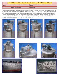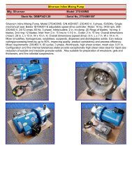
Viking Pump with Motor and Gear Reduction Drive - Genemco, Inc.
Viking Pump with Motor and Gear Reduction Drive - Genemco, Inc.
Viking Pump with Motor and Gear Reduction Drive - Genemco, Inc.

Create successful ePaper yourself
Turn your PDF publications into a flip-book with our unique Google optimized e-Paper software.
If pump is equipped <strong>with</strong> jacketed head plate, install<br />
at this time along <strong>with</strong> new gasket.<br />
Tighten head capscrews evenly.<br />
Remove tapered installation sleeve from the shaft.<br />
11. Slide inner spacer collar over shaft <strong>with</strong> recessed end<br />
facing rotor. G, H <strong>and</strong> HL size bearing spacer collars are<br />
not recessed.<br />
Place pair of half round rings on shaft <strong>and</strong> slide inner<br />
bearing spacer collar over half round rings to lock them<br />
in place. There is no pair of half round rings on G, H <strong>and</strong><br />
HL size pumps. Refer to Figure 6, page 4.<br />
12. Press lip seal, lip facing end of shaft, in inner end cap<br />
<strong>and</strong> insert end cap through shaft end of bracket. Turn<br />
end cap clockwise, looking at shaft end, until it engages<br />
threads. End cap spanner wrench holes must be facing<br />
rotor. Turn end cap <strong>with</strong> spanner wrench until it projects<br />
slightly from opening on side of bracket. End cap must<br />
not be turned so far that lip seal drops off end of spacer<br />
collar on shaft or end cap becomes disengaged from<br />
threads. Refer to Figure 6, page 4.<br />
If this happens, remove inner spacer collar, half round<br />
rings <strong>and</strong> end cap <strong>and</strong> start over at Step 11.<br />
13. Pack ball bearing <strong>with</strong> multi-purpose grease, NLGI #2.<br />
Place on shaft <strong>and</strong> push or gently drive in place in<br />
bracket.<br />
14. Press lip seal, lip facing end of shaft, in outer end cap<br />
<strong>and</strong> insert end cap in bracket. Turn end cap in bracket<br />
until it is tight against bearing. Refer to Figure 6, page 4.<br />
15. Put lockwasher <strong>and</strong> locknut on shaft. Insert length of<br />
hardwood or brass through port opening between rotor<br />
teeth to keep shaft from turning. Tighten locknut <strong>and</strong><br />
bend one tang of lockwasher into slot of locknut. There is<br />
no lockwasher on G size pump.<br />
16. Adjust pump end clearance. Refer to Thrust Bearing<br />
Adjustment, page 13.<br />
17. Lubricate the grease fitting over the seal chamber <strong>with</strong><br />
petroleum jelly, petrolatum (Vasoline) or other similar low<br />
melting point lubricant. Lubricate all other grease fittings<br />
<strong>with</strong> multi-purpose greas e, NLGI #2.<br />
ASSEMBLY<br />
Optional Mechanical Seal<br />
(Teflon Fitted Type)<br />
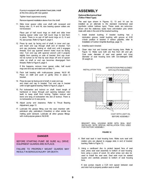
The seal type shown in Figures 12, 13 <strong>and</strong> 14 can be<br />
installed as an alternate to the st<strong>and</strong>ard mechanical seal<br />
(synthetic rubber bellows type). These seals are setscrew<br />
driven <strong>and</strong> the stationary seats have anti-rotation pins which<br />
mate <strong>with</strong> slots in the end of the bracket bushing.<br />
1. Install bracket bushing. If bracket bushing has a<br />
lubrication groove, install bushing <strong>with</strong> groove at 6:00<br />
o’clock position in bracket. If carbon graphite, refer to<br />
Installation of Carbon Graphite Bushings, page 13.<br />
2. Install lip seal in bracket.<br />
3. Clean rotor hub <strong>and</strong> bracket seal housing bore. Refer to<br />
Figure 12. Make sure both are free from dirt <strong>and</strong> grit.<br />
Coat outer diameter of seal seat gasket <strong>and</strong> inner<br />
diameter of seal housing bore <strong>with</strong> non-detergent SAE<br />
30 weight oil.<br />
INSTALLATION TOOL<br />
ANTI-ROTATION PINS ALIGNED<br />
WITH SLOTS IN BUSHING<br />
COAT WITH LIGHT OIL<br />
BEFORE ASSEMBLY<br />
BRACKET SEAL HOUSING BORE WITH SEAL SEAT<br />
INSTALLED. NOTE SPECIAL INSTALLATION TOOL USED<br />
FOR FACTORY ASSEMBLY.<br />
DANGER<br />
BEFORE STARTING PUMP, BE SURE ALL DRIVE<br />
EQUIPMENT GUARDS ARE IN PLACE.<br />
FAILURE TO PROPERLY MOUNT GUARDS MAY<br />
RESULT IN SERIOUS INJURY OR DEATH.<br />
FIGURE 12<br />
4. Start seal seat in seal housing bore. Make sure seat antirotation<br />
pins are aligned to engage slots in end of bracket<br />
bushing. Refer to Figure 12.<br />
5. Using a cardboard disc to protect lapped face of seal<br />
seat, press seal seat assembly to bottom of seal housing<br />
bore using a piece of wood. An arbor press can also be<br />
used to install the seal seat. Seal seat must be started<br />
square <strong>and</strong> carefully pressed to bottom of seal housing<br />
bore.<br />
K size pumps require a 0.25 inch spacer between seal<br />
<strong>and</strong> rotor hub to properly position seal on shaft.<br />
9