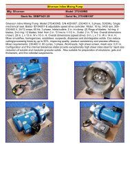
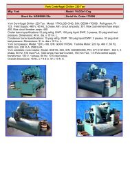
Viking Pump with Motor and Gear Reduction Drive - Genemco, Inc.
Viking Pump with Motor and Gear Reduction Drive - Genemco, Inc.
Viking Pump with Motor and Gear Reduction Drive - Genemco, Inc.

You also want an ePaper? Increase the reach of your titles
YUMPU automatically turns print PDFs into web optimized ePapers that Google loves.
Prior to installing rotating portion of mechanical seal, prepare<br />
<strong>and</strong> organize rotor shaft, head <strong>and</strong> idler assemblies <strong>and</strong><br />
appropriate gaskets for quick assembly.<br />
Once rotating portion of mechanical seal is installed on rotor<br />
shaft, it is necessary to assemble parts as quickly as<br />
possible to insure that seal does not stick to shaft in wrong<br />
axial position. The seal should be expected to stick to the<br />
shaft after several minutes setting time.<br />
Never touch sealing faces <strong>with</strong> anything except clean h<strong>and</strong>s<br />
or clean cloth. Minute particles can scratch the seal faces<br />
<strong>and</strong> cause leakage.<br />
3. Coat idler pin <strong>with</strong> non-detergent SAE 30 weight oil <strong>and</strong><br />
place idler <strong>and</strong> bushing on idler pin in head. If replacing<br />
a carbon graphite bushing, refer to Installation of Carbon<br />
Graphite Bushings, page 13.<br />
4. Clean rotor hub <strong>and</strong> bracket seal housing bore. Make<br />
sure both are free from dirt <strong>and</strong> grit. Coat outer diameter<br />
of seal seat <strong>and</strong> inner diameter of seal housing bore <strong>with</strong><br />
non-detergent SAE 30 weight oil.<br />
5. Start seal seat in seal housing bore, refer to Figure 9. If<br />
force is necessary, protect seal face <strong>with</strong> a clean<br />
cardboard disc <strong>and</strong> gently tap it in place <strong>with</strong> a piece of<br />
wood.<br />
COAT SEAL SEAT AND SEAL HOUSING BORE<br />
WITH NON-DETERGENT SAE 30 WEIGHT OIL<br />
BEFORE ASSEMBLY.<br />
SPRING<br />
SHAFT<br />
COAT ROTOR SHAFT, TAPERED INSTALLATION SLEEVE<br />
AND INNER DIAMETER OF MECHANICAL SEAL WITH NON-<br />
DETERGENT SAE 30 WEIGHT OIL BEFO RE ASSEMBLY.<br />
ROTOR HUB<br />
MECHANICAL SEAL ROTARY MEMBER<br />
SPRING<br />
FIGURE 10<br />
TAPERED<br />
INSTALLATION SLEEVE<br />
MECHANICAL SEAL<br />
ROTARY MEMBER<br />
SHAFT<br />
BRACKET<br />
BUSHING<br />
LIP SEAL FOR<br />
SEAL CHAMBER<br />
FIGURE 11<br />
7. Place seal spring on shaft against rotor hub. Refer to<br />
Figure 11.<br />
8. Slide rotary member, lapped contact surface facing away<br />
from spring, over installation sleeve on shaft until it is<br />
against spring.<br />
SEAL HOUSING<br />
BORE<br />
SEAL SEAT<br />
BRACKET BUSHING<br />
LUBRICATION GROOVE<br />
IN 6:00 O’CLOCK<br />
POSITION<br />
FIGURE 9<br />
BRACKET<br />
6. Place tapered installation sleeve on shaft, refer to Figure<br />
10. Sleeve is furnished <strong>with</strong> H, HL, K, KK, L, LO <strong>and</strong> LL<br />
size replacement mechanical seals. Coat rotor shaft,<br />
tapered installation sleeve <strong>and</strong> inner diameter of<br />
mechanical seal rotary member <strong>with</strong> a generous amount<br />
of non-detergent SAE 30 weight oil. Petrolatum may be<br />
used but grease is not recommended.<br />
Do not compress spring.<br />
9. Coat rotor shaft <strong>with</strong> non-detergent SAE 30 weight oil.<br />
Start end of shaft in bracket bushing <strong>and</strong> turn from right<br />
to left, slowly pushing until the ends of the rotor teeth are<br />
just below the face of the casing.<br />
Leave the rotor in this position. Withdrawal of rotor <strong>and</strong><br />
shaft may displace the carbon seal rotating face <strong>and</strong><br />
result in damage to the seal.<br />
10. Using a .010 to .015 inch head gasket, install head <strong>and</strong><br />
idler assembly on pump. <strong>Pump</strong> head <strong>and</strong> casing were<br />
marked before disassembly to insure proper reassembly.<br />
If not, be sure idler pin, which is offset in pump head, is<br />
positioned toward <strong>and</strong> equal distance between port<br />
connections to allow for proper flow of liquid through<br />
pump.<br />
8