Viking Pump with Motor and Gear Reduction Drive - Genemco, Inc.
Viking Pump with Motor and Gear Reduction Drive - Genemco, Inc.
Viking Pump with Motor and Gear Reduction Drive - Genemco, Inc.

Create successful ePaper yourself
Turn your PDF publications into a flip-book with our unique Google optimized e-Paper software.
End cap must not be turned so far that lip seal drops off<br />
end of spacer collar on shaft or end cap becomes<br />
disengaged from threads. Refer to Figure 6, page 4.<br />
If this happens, remove inner spacer collar, half round<br />
rings <strong>and</strong> end cap <strong>and</strong> start over at Step 15.<br />
16. Pack ball bearing <strong>with</strong> multi-purpose grease, NLGI #2.<br />
Place on shaft <strong>and</strong> push or gently drive in place in<br />
bracket.<br />
17. Press lip seal, lip facing end of shaft, in outer end cap<br />
<strong>and</strong> insert end cap in bracket. Turn end cap in bracket<br />
until it is tight against bearing. Refer to Figure 6, page 4.<br />
18. Insert length of hardwood or brass through port opening<br />
between rotor teeth to keep shaft from turning. Put<br />
lockwasher <strong>and</strong> locknut on shaft, tighten <strong>and</strong> bend one<br />
tang of lockwasher into slot of locknut.<br />
19. Adjust pump end clearance. Refer to Thrust Bearing<br />
Adjustment, below.<br />
20. Lubricate all grease fittings <strong>with</strong> multi-purpose grease,<br />
NLGI #2.<br />
DANGER<br />
BEFORE STARTING PUMP, BE SURE ALL DRIVE<br />
EQUIPMENT GUARDS ARE IN PLACE.<br />
FAILURE TO PROPERLY MOUNT GUARDS MAY<br />
RESULT IN SERIOUS INJURY OR DEATH.<br />
THRUST BEARING ADJUSTMENT<br />
1. Loosen setscrews over outer <strong>and</strong> inner end caps. Two<br />
for G, H <strong>and</strong> HL size pumps, four for all other sizes.<br />
2. Turn inner end cap clockwise, viewed from shaft end,<br />
until it projects slightly from bracket exposing<br />
approximately three threads.<br />
3. Turn outer end cap clockwise until rotor is tight against<br />
head <strong>and</strong> rotor shaft cannot be turned.<br />
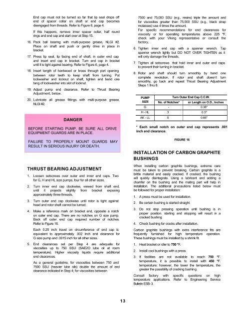
4. Make a reference mark on bracket end, opposite a notch<br />
on outer end cap. There are no notches on G size pump.<br />
Back off outer end cap required number of notches.<br />
Refer to Figure 16.<br />
Each 0.25 inch travel on circumference of end cap is<br />
equivalent to approximately .002 inch end clearance for<br />
G size pump <strong>and</strong> .0015 inch for all other sizes.<br />
5. End clearances set per Step 4 are adequate for<br />
viscosities up to 750 SSU (SAE2O lube oil at room<br />
temperature). Higher viscosity liquids require additional<br />
end clearances.<br />
As a general guideline, for viscosities between 750 <strong>and</strong><br />
7500 SSU (heavier lube oils) double the amount of end<br />
clearance indicated in Step 4; for viscosities between<br />
7500 <strong>and</strong> 75,000 SSU (e.g., resins) triple the amount <strong>and</strong><br />
for viscosities greater than 75,000 SSU (e.g., black strap<br />
molasses) use 4 times the amount.<br />
For specific recommendations for end clearances for<br />
viscosity or for operating temperatures above 225 °F,<br />
check <strong>with</strong> your <strong>Viking</strong> representative or consult the<br />
factory.<br />
6. Tighten inner end cap <strong>with</strong> a spanner wrench. Tap<br />
spanner wrench lightly but DO NOT OVER TIGHTEN as it<br />
will only damage the threads.<br />
7. Tighten all setscrews that hold inner <strong>and</strong> outer end caps<br />
to prevent their turning in bracket.<br />
8. Rotor <strong>and</strong> shaft should turn smoothly by h<strong>and</strong> one<br />
complete revolution. If rotor <strong>and</strong> shaft doesn’t turn<br />
smoothly, go back <strong>and</strong> repeat Thrust Bearing Adjustment<br />
Steps 1 thru 8.<br />
PUMP<br />
Turn Outer End Cap C.C.W.<br />
SIZE No. of Notches* or Length on O.D., <strong>Inc</strong>hes<br />
G - 0.38"<br />
H - HL 3 0.5"<br />
AK - LL 5 0.66"<br />
* Each small notch on outer end cap represents .001<br />
inch end clearance.<br />
INSTALLATION OF CARBON GRAPHITE<br />
BUSHINGS<br />
When installing carbon graphite bushings, extreme care<br />
must be taken to prevent breaking. Carbon graphite is a<br />
brittle material <strong>and</strong> easily cracked. If cracked, the bushing<br />
will quickly disintegrate. Using a lubricant <strong>and</strong> adding a<br />
chamfer on the bushing <strong>and</strong> the mating part will help in<br />
installation. The additional pr ecautions listed below must<br />
be followed for proper installation:<br />
1. A press must be used for installation.<br />
2. Be certain bushing is started straight.<br />
3. Do not stop pressing operation until bushing is in<br />
proper position. starting <strong>and</strong> stopping will result in a<br />
cracked bushing.<br />
4. Check bushing for cracks after installation.<br />
Carbon graphite bushings <strong>with</strong> extra interference fits are<br />
frequently furnished for high temperature operation.<br />
These bushings must be installed by a shrink fit.<br />
1. Heat bracket or idler to 750 °F.<br />
FIGURE 16<br />
2. Install cool bushings <strong>with</strong> a press.<br />
3. If facilities are not available to reach 750 °F.<br />
temperature, it is possible to install <strong>with</strong> 450 °F.<br />
temperature; however, the lower the temperature, the<br />
greater the possibility of cracking bushing.<br />
Consult factory <strong>with</strong> specific questions on high<br />
temperature applications. Refer to Engineering Service<br />
Bulletin ESB-3.<br />
13