Viking Pump with Motor and Gear Reduction Drive - Genemco, Inc.
Viking Pump with Motor and Gear Reduction Drive - Genemco, Inc.
Viking Pump with Motor and Gear Reduction Drive - Genemco, Inc.

You also want an ePaper? Increase the reach of your titles
YUMPU automatically turns print PDFs into web optimized ePapers that Google loves.
DISASSEMBLY<br />
DANGER<br />
BEFORE OPENING ANY VIKING PUMP LIQUID<br />
CHAMBER (PUMPING CHAMBER, RESERVOIR,<br />
RELIEF VALVE ADJUSTING CAP FITTING ETC.)<br />
BE SURE:<br />
6. Carefully remove rotor <strong>and</strong> shaft to avoid damaging<br />
bracket bushing.<br />
7. Remove packing gl<strong>and</strong> from side of bracket.<br />
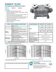
GREASE FITTING LOCATION<br />
1. THAT ANY PRESSURE IN CHAMBER HAS<br />
BEEN COMPLETELY VENTED THROUGH<br />
SUCTION OR DISCHARGE LINES OR<br />
OTHER APPROPRIATE OPENINGS OR<br />
CONNECTIONS.<br />
2. THAT THE DRIVING MEANS (MOTOR,<br />
TURBINE, ENGINE, ETC.) HAS BEEN<br />
“LOCKED OUT” OR MADE NON-<br />
OPERATIONAL SO THAT IT CANNOT BE<br />
STARTED WHILE WORK IS BEING DONE<br />
ON PUMP.<br />
3. THAT YOU KNOW WHAT LIQUID THE PUMP<br />
HAS BEEN HANDLING AND THE<br />
PRECAUTIONS NECESSARY TO SAFELY<br />
HANDLE THE LIQUID. OBTAIN A MATERIAL<br />
SAFETY DATA SHEET (MSDS) FOR THE<br />
LIQUID TO BE SURE THESE PRECAUTIONS<br />
ARE UNDERSTOOD.<br />
NYLON INSET<br />
INNER<br />
END CAP<br />
HALF ROUND<br />
RINGS<br />
INNER<br />
SPACER<br />
COLLAR<br />
INNER LIP SEAL<br />
BALL<br />
BEARING<br />
SETSCREWS<br />
BRACKET<br />
OUTER END CAP<br />
LOCKWASHER<br />
LOCKNUT<br />
OUTER LIP<br />
SEAL<br />
OUTER<br />
SPACER<br />
COLLAR<br />
FAILURE TO FOLLOW ABOVE LISTED<br />
PRECAUTIONARY MEASURES MAY RESULT IN<br />
SERIOUS INJURY OR DEATH.<br />
1. Mark head <strong>and</strong> casing before disassembly to insure<br />
proper reassembly. The idler pin, which is offset in pump<br />
head, must be positioned toward <strong>and</strong> equal distance<br />
between port connections to allow for proper flow of liquid<br />
through pump.<br />
Remove head from pump. Do not allow idler to fall from<br />
idler pin. Tilt top of head back when removing to prevent<br />
this. Avoid damaging head gasket. If pump is furnished<br />
<strong>with</strong> pressure relief valve, it need not be removed from<br />
head or disassembled at this point. Refer to Pressure<br />
Relief Valve Instructions, page 14.<br />
If pump has jacketed head plate, it will separate from<br />
head when it is removed. The gasket between head <strong>and</strong><br />
jacket head plate must be totally removed. Use new<br />
gasket when assembling pump.<br />
2. Remove idler <strong>and</strong> bushing assembly.<br />
3. Insert length of hardwood or brass through port opening<br />
between rotor teeth to keep shaft from turning. Bend up<br />
tang of lockwasher <strong>and</strong> <strong>with</strong> a spanner wrench remove<br />
locknut <strong>and</strong> lockwasher from shaft. There is no<br />
lockwasher on G size pump.<br />
4. Remove packing gl<strong>and</strong> nuts.<br />
5. Tap shaft forward approximately 0.5 inch <strong>and</strong> remove pair<br />
of half round rings under inner bearing spacer collar.<br />
There is no pair of half round rings on G, H <strong>and</strong> HL size<br />
pumps.<br />
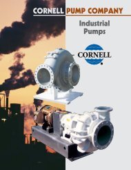
8. Loosen setscrews. Two on G, H <strong>and</strong> HL size pumps,<br />
four on all other sizes. With a spanner wrench, remove<br />
both end caps <strong>with</strong> lip seals. Remove ball bearing <strong>and</strong><br />
spacer collars. Refer to Figure 6.<br />
9. Remove packing <strong>and</strong> packing retainer washer.<br />
10. Clean all parts thoroughly <strong>and</strong> examine for wear <strong>and</strong><br />
damage. Check lip seals, ball bearing, bushings <strong>and</strong><br />
idler pin <strong>and</strong> replace if necessary. Check all other parts<br />
for nicks, burrs, excessive wear <strong>and</strong> replace if<br />
necessary.<br />
Wash bearings in clean solvent. Blow out bearings <strong>with</strong><br />
compressed air. Do not allow bearings to spin; turn them<br />
slowly by h<strong>and</strong>. Spinning bearings will damage race <strong>and</strong><br />
balls. Make sure bearings are clean, then lubricate <strong>with</strong><br />
non-detergent SAE 30 weight oil <strong>and</strong> check for<br />
roughness. Roughness can be determined by turning<br />
outer race by h<strong>and</strong>.<br />
11. Casing can be checked for wear or damage while<br />
mounted on bracket.<br />
ASSEMBLY<br />
FIGURE 6<br />
1. Install bracket bushing. If bracket bushing has a<br />
lubrication groove, install bushing <strong>with</strong> groove at 6:00<br />
o’clock position in bracket. If carbon graphite, refer to<br />
Installation of Carbon Graphite Bushings, page 13.<br />
2. Coat shaft of rotor shaft assembly <strong>with</strong> non-detergent<br />
SAE 30 weight oil. Start end of shaft in bracket bushing<br />
turning from right to left, slowly pushing rotor in casing.<br />
4