√α Σ - Industrial Technologies
√α Σ - Industrial Technologies
√α Σ - Industrial Technologies

Create successful ePaper yourself
Turn your PDF publications into a flip-book with our unique Google optimized e-Paper software.
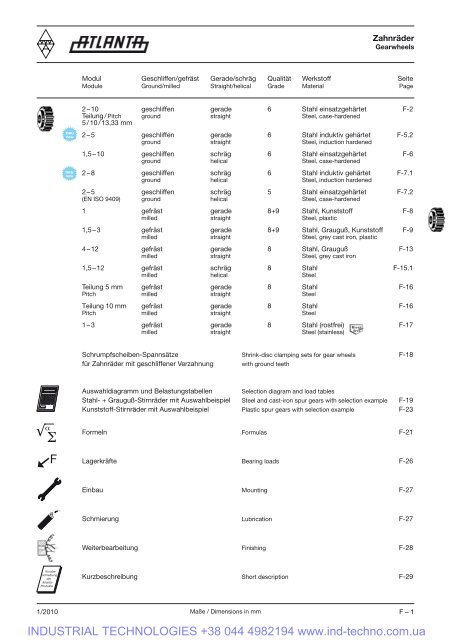
Zahnräder<br />
Gearwheels<br />
Modul Geschliffen/gefräst Gerade/schräg Qualität Werkstoff Seite<br />
Module Ground/milled Straight/helical Grade Material Page<br />
neu<br />
new<br />
neu<br />
new<br />
2 – 10 geschliffen gerade 6 Stahl einsatzgehärtet F-2<br />
Teilung / Pitch ground straight Steel, case-hardened<br />
5 / 10 / 13,33 mm<br />
2 – 5 geschliffen gerade 6 Stahl induktiv gehärtet F-5.2<br />
ground straight Steel, induction hardened<br />
1,5 – 10 geschliffen schräg 6 Stahl einsatzgehärtet F-6<br />
ground helical Steel, case-hardened<br />
2 – 8 geschliffen schräg 6 Stahl induktiv gehärtet F-7.1<br />
ground helical Steel, induction hardened<br />
2 – 5 geschliffen schräg 5 Stahl einsatzgehärtet F-7.2<br />
(EN ISO 9409) ground helical Steel, case-hardened<br />
1 gefräst gerade 8+9 Stahl, Kunststoff F-8<br />
milled straight Steel, plastic<br />
1,5 – 3 gefräst gerade 8+9 Stahl, Grauguß, Kunststoff F-9<br />
milled straight Steel, grey cast iron, plastic<br />
4 – 12 gefräst gerade 8 Stahl, Grauguß F-13<br />
milled straight Steel, grey cast iron<br />
1,5 – 12 gefräst schräg 8 Stahl F-15.1<br />
milled helical Steel<br />
Teilung 5 mm gefräst gerade 8 Stahl F-16<br />
Pitch milled straight Steel<br />
Teilung 10 mm gefräst gerade 8 Stahl F-16<br />
Pitch milled straight Steel<br />
1 – 3 gefräst gerade 8 Stahl (rostfrei) F-17<br />
milled straight Steel (stainless)<br />
Schrumpfscheiben-Spannsätze Shrink-disc clamping sets for gear wheels F-18<br />
für Zahnräder mit geschliffener Verzahnung with ground teeth<br />
Auswahldiagramm und Belastungstabellen Selection diagram and load tables<br />
Stahl- + Grauguß-Stirnräder mit Auswahlbeispiel Steel and cast-iron spur gears with selection example F-19<br />
Kunststoff-Stirnräder mit Auswahlbeispiel Plastic spur gears with selection example F-23<br />
√ α <strong>Σ</strong><br />
F<br />
Formeln Formulas F-21<br />
Lagerkräfte Bearing loads F-26<br />
Einbau Mounting F-27<br />
Schmierung Lubrication F-27<br />
Weiterbearbeitung Finishing F-28<br />
Kurzbeschreibung<br />
der<br />
Atlanta-<br />
Produkte<br />
Kurzbeschreibung Short description F-29<br />
1/2010<br />
Maße / Dimensions in mm F – 1<br />
INDUSTRIAL TECHNOLOGIES +38 044 4982194 www.ind-techno.com.ua
t<br />
Zahnräder mit geschliffener Verzahnung – Modul 2<br />
Gearwheels with ground teeth – module 2<br />
gerade verzahnt, Verzahnung geschliffen, 20° Eingriffswinkel, mit Bohrung Ø H6 und Passfedernut nach DIN 6885<br />
Straight tooth system, ground teeth, 20° transverse pressure angle, with bore Ø H6 and keyway acc. to DIN 6885<br />
0,01 A u 0,2 B<br />
b 2<br />
B<br />
➚ 0,05 A<br />
b 2<br />
b 1<br />
16MnCr5, 1.7131<br />
einsatzgehärtet<br />
case-hardened<br />
d k<br />
d<br />
d N<br />
d k<br />
d<br />
d Nh8<br />
Verz.-Qual.<br />
Gearing grade<br />
6 e 25<br />
b 1<br />
Bild 1<br />
Fig. 1<br />
d 1<br />
Bild 1 + 3 Nut Mitte Zahnlücke<br />
Fig. 1 + 3 Keyway middle of tooth gap<br />
A<br />
Bild 3<br />
Fig. 3<br />
Bestell-Nr. Bild Zähnezahl<br />
Order code Fig. N° of teeth<br />
z d d k d H6 1 d N b 1 b 2 u t<br />
Spannsatz<br />
lt. Seite F-18<br />
shrink-disc<br />
on page F-18<br />
Modul / Module 2<br />
24 21 216 1 16 32 36 15 25 28 30,0 5 17,3 0,1<br />
24 21 218 1 18 36 40 15 28 28 30,0 5 17,3 0,2<br />
24 22 218 1 18 36 40 20 28 28 30,0 6 22,8 0,2<br />
24 21 220 1 20 40 44 15 25 28 30,0 5 17,3 0,2<br />
24 29 420 3 20 40 44 19* 30 28 30,0 6 21,8 0,2 80 83 030<br />
24 29 220 1 20 40 44 19* 30 28 30,0 6 21,8 0,2<br />
24 22 220 1 20 40 44 20* 30 28 30,0 6 22,8 0,2<br />
24 20 120 3 20 40 44 22* 36 28 56,0 6 24,8 0,2 80 84 036<br />
24 20 220 1 20 40 44 22* 30 28 30,0 6 24,8 0,2<br />
24 21 222 1 22 44 48 15 25 28 30,0 5 17,3 0,3<br />
24 29 222 1 22 44 48 19* 30 28 30,0 6 21,8 0,2<br />
24 29 422 3 22 44 48 19* 30 28 56,0 6 21,8 0,3 80 83 030<br />
24 22 222 1 22 44 48 20 30 28 30,0 6 22,8 0,3<br />
24 20 222 1 22 44 48 22* 30 28 30,0 6 24,8 0,2<br />
24 20 122 3 22 44 48 22 36 28 56,0 6 27,8 0,3 80 84 036<br />
24 23 222 1 22 44 48 25 36 28 30,0 8 28,3 0,2<br />
24 21 225 1 25 50 54 15 25 28 30,0 5 17,3 0,4<br />
24 26 225 3 25 50 54 16 30 28 54,0 5 18,3 0,3 80 83 030<br />
24 29 225 1 25 50 54 19* 30 28 30,0 6 21,8 0,3<br />
24 29 425 3 25 50 54 19* 30 28 56,0 6 21,8 0,4 80 83 030<br />
24 22 225 1 25 50 54 20 30 28 30,0 6 22,8 0,4<br />
24 20 225 1 25 50 54 22 30 28 30,0 6 24,8 0,3<br />
24 20 425 3 25 50 54 22* 36 28 56,0 6 24,8 0,4 80 84 036<br />
24 23 225 1 25 50 54 25 36 28 30,0 8 28,3 0,3<br />
24 24 225 1 25 50 54 30 45 28 30,0 8 33,3 0,3<br />
24 21 228 1 28 56 60 15 25 28 30,0 5 17,3 0,4<br />
24 29 228 1 28 56 60 19* 30 28 30,0 6 21,8 0,4<br />
24 29 428 3 28 56 60 19* 30 28 56,0 6 21,8 0,5 80 83 030<br />
24 22 228 1 28 56 60 20 30 28 30,0 6 22,8 0,5<br />
24 20 128 3 28 56 60 22* 36 28 56,0 6 24,8 0,3 80 84 036<br />
24 20 228 1 28 56 60 22* 30 28 30,0 6 24,8 0,3<br />
24 23 228 1 28 56 60 25 36 28 30,0 8 28,3 0,4<br />
24 22 428 3 28 56 60 30 50 28 60,0 8 33,3 0,4 80 85 050<br />
24 24 228 1 28 56 60 30 45 28 30,0 8 33,3 0,4<br />
24 25 228 1 28 56 60 35 48 28 30,0 10 38,3 0,3<br />
24 21 232 1 32 64 68 15 36 28 30,0 5 17,3 0,6<br />
24 26 232 3 32 64 68 16 30 28 54,0 5 18,3 0,6 80 83 030<br />
24 22 232 1 32 64 68 20 30 28 30,0 6 22,8 0,6<br />
24 20 232 1 32 64 68 22* 30 28 30,0 6 24,8 0,4<br />
24 20 432 3 32 64 68 22 36 28 56,0 6 24,8 0,6 80 84 036<br />
24 23 232 1 32 64 68 25 36 28 30,0 8 28,3 0,6<br />
24 22 432 3 32 64 68 30 50 28 60,0 8 33,3 0,6 80 85 050<br />
24 24 232 1 32 64 68 30 45 28 30,0 8 33,3 0,6<br />
24 23 432 3 32 64 68 32 55 28 65,0 10 35,3 0,5 80 80 055<br />
24 25 232 1 32 64 68 35 48 28 30,0 10 38,3 0,5<br />
24 22 236 1 36 72 76 20 30 28 30,0 6 22,8 0,8<br />
24 23 236 1 36 72 76 25 36 28 30,0 8 28,3 0,8<br />
24 24 236 1 36 72 76 30 45 28 30,0 8 33,3 0,7<br />
24 25 236 1 36 72 76 35 48 28 30,0 10 38,3 0,7<br />
24 25 436 3 36 72 76 40 62 28 65,0 12 43,3 0,5 80 86 062<br />
24 27 236 1 36 72 76 45 58 28 30,0 14 48,8 0,6<br />
* G6 bzw./resp. H7<br />
F – 2 Maße / Dimensions in mm<br />
1/2010<br />
INDUSTRIAL TECHNOLOGIES +38 044 4982194 www.ind-techno.com.ua
t<br />
Zahnräder mit geschliffener Verzahnung – Modul 2<br />
Gearwheels with ground teeth – module 2<br />
gerade verzahnt, Verzahnung geschliffen, 20° Eingriffswinkel, mit Bohrung Ø H6 und Passfedernut nach DIN 6885<br />
Straight tooth system, ground teeth, 20° transverse pressure angle, with bore Ø H6 and keyway acc. to DIN 6885<br />
0,01 A u 0,2 B<br />
b 2<br />
B<br />
➚ 0,05 A<br />
b 2<br />
b 1<br />
16MnCr5, 1.7131<br />
einsatzgehärtet<br />
case-hardened<br />
d k<br />
d<br />
d N<br />
d k<br />
d<br />
d Nh8<br />
Verz.-Qual.<br />
Gearing grade<br />
6 e 25<br />
b 1<br />
Bild 1<br />
Fig. 1<br />
d 1<br />
Bild 1 + 3 Nut Mitte Zahnlücke<br />
Fig. 1 + 3 Keyway middle of tooth gap<br />
A<br />
Bild 3<br />
Fig. 3<br />
Bestell-Nr. Bild Zähnezahl<br />
Order code Fig. N° of teeth<br />
z d d k d H6 1 d N b 1 b 2 u t<br />
Spannsatz<br />
lt. Seite F-18<br />
shrink-disc<br />
on page F-18<br />
Modul / Module 2<br />
24 21 240 1 40 80 84 15 36 28 30,0 5 17,3 1,0<br />
24 22 240 1 40 80 84 20 30 28 30,0 6 22,8 1,0<br />
24 23 240 1 40 80 84 25 36 28 30,0 8 28,3 1,0<br />
24 24 240 1 40 80 84 30 45 28 30,0 8 33,3 1,0<br />
24 23 440 3 40 80 84 32 55 28 65,0 10 35,3 0,9 80 85 050<br />
24 25 240 1 40 80 84 35 48 28 30,0 10 38,3 0,9<br />
24 25 440 3 40 80 84 40 62 28 65,0 12 43,3 0,7 80 86 062<br />
24 26 440 3 40 80 84 45 68 28 65,0 14 48,8 1,3 80 80 068<br />
24 27 240 1 40 80 84 45 58 28 30,0 14 48,8 0,8<br />
24 22 245 1 45 90 94 20 30 28 30,0 6 22,8 1,3<br />
24 23 245 1 45 90 94 25 36 28 30,0 8 28,3 1,2<br />
24 25 245 1 45 90 94 35 48 28 30,0 10 38,3 1,2<br />
24 27 245 1 45 90 94 45 58 28 30,0 14 48,8 1,1<br />
24 22 250 1 50 100 104 20 30 28 30,0 6 22,8 1,6<br />
24 23 250 1 50 100 104 25 36 28 30,0 8 28,3 1,5<br />
24 25 250 1 50 100 104 35 48 28 30,0 10 38,3 1,5<br />
24 27 250 1 50 100 104 45 58 28 30,0 14 48,8 1,4<br />
24 26 450 3 50 100 104 45 68 28 65,0 14 48,8 2,0 80 80 068<br />
24 23 256 1 56 112 116 25 36 28 30,0 8 28,3 1,9<br />
24 25 256 1 56 112 116 35 48 28 30,0 10 38,3 1,8<br />
24 23 263 1 63 126 130 25 36 28 30,0 8 28,3 2,5<br />
24 25 271 1 71 142 146 35 48 28 30,0 10 38,3 3,15<br />
24 25 280 1 80 160 164 35 48 28 30,0 10 38,3 4,2<br />
24 27 290 1 90 180 184 45 58 28 30,0 14 48,8 5,7<br />
1/2010<br />
Maße / Dimensions in mm F – 3<br />
INDUSTRIAL TECHNOLOGIES +38 044 4982194 www.ind-techno.com.ua
t<br />
Zahnräder mit geschliffener Verzahnung – Modul 3<br />
Gearwheels with ground teeth – module 3<br />
gerade verzahnt, Verzahnung geschliffen, 20° Eingriffswinkel, mit Bohrung Ø H6 und Passfedernut nach DIN 6885<br />
Straight tooth system, ground teeth, 20° transverse pressure angle, with bore Ø H6 and keyway acc. to DIN 6885<br />
0,01 A u 0,2 B<br />
b 2<br />
B<br />
➚ 0,05 A<br />
b 2<br />
b 1<br />
16MnCr5, 1.7131<br />
einsatzgehärtet<br />
case-hardened<br />
d k<br />
d<br />
d N<br />
d k<br />
d<br />
d Nh8<br />
Verz.-Qual.<br />
Gearing grade<br />
6 e 25<br />
b 1<br />
Bild 1<br />
Fig. 1<br />
d 1<br />
Bild 1 + 3 Nut Mitte Zahnlücke<br />
Fig. 1 + 3 Keyway middle of tooth gap<br />
A<br />
Bild 3<br />
Fig. 3<br />
Bestell-Nr. Bild Zähnezahl<br />
Order code Fig. N° of teeth<br />
z d d k d H6 1 d N b 1 b 2 u t<br />
Spannsatz<br />
lt. Seite F-18<br />
shrink-disc<br />
on page F-18<br />
Modul / Module 3<br />
24 33 218 1 18 54 60 25 36 28 30,0 8 28,3 0,4<br />
24 33 220 1 20 60 66 25 36 28 30,0 8 28,3 0,5<br />
24 34 220 1 20 60 66 30 45 28 30,0 8 33,3 0,5<br />
24 35 220 1 20 60 66 35 48 28 30,0 10 38,3 0,4<br />
24 30 422 3 22 66 72 22 36 28 56,0 6 24,8 0,8 80 84 036<br />
24 31 422 3 22 66 72 25 44 28 60,0 8 28,3 0,9 80 80 044<br />
24 33 222 1 22 66 72 25 36 28 30,0 8 28,3 0,6<br />
24 32 422 3 22 66 72 30 50 28 60,0 8 33,3 0,9 80 85 050<br />
24 34 222 1 22 66 72 30 45 28 30,0 8 33,3 0,6<br />
24 33 422 3 22 66 72 32 55 28 65,0 10 35,3 1,0 80 80 055<br />
24 34 422 3 22 66 72 35 55 28 65,0 10 38,3 0,9 80 80 055<br />
24 35 222 1 22 66 72 35 48 28 30,0 10 38,3 0,6<br />
24 35 422 3 22 66 72 40* 62 28 65 12 43,3 1,0 80 86 062<br />
24 33 225 1 25 75 81 25 36 28 30,0 8 28,3 0,9<br />
24 34 225 1 25 75 81 30 45 28 30,0 8 33,3 0,8<br />
24 33 425 3 25 75 81 32* 55 28 65 10 35,3 1,2 80 80 055<br />
24 35 225 1 25 75 81 35 48 28 30,0 10 38,3 0,8<br />
24 35 425 3 25 75 81 40 62 28 65,0 12 43,3 1,2 80 86 062<br />
24 37 225 1 25 75 81 45 58 28 30,0 14 48,8 0,6<br />
24 30 428 3 28 84 90 22 36 28 56,0 6 24,8 1,3 80 84 036<br />
24 31 428 3 28 84 90 25 44 28 60,0 8 28,3 1,4 80 80 044<br />
24 33 228 1 28 84 90 25 36 28 30,0 8 28,3 1,1<br />
24 32 428 3 28 84 90 30 50 28 60,0 8 33,3 1,4 80 85 050<br />
24 34 228 1 28 84 90 30 45 28 30,0 8 33,3 1,1<br />
24 33 428 3 28 84 90 32 55 28 65,0 10 35,3 1,5 80 80 055<br />
24 34 428 3 28 84 90 35 55 28 65,0 10 38,3 1,4 80 80 055<br />
24 35 228 1 28 84 90 35 48 28 30,0 10 38,3 1,0<br />
24 35 428 3 28 84 90 40* 62 28 65 12 43,3 1,4 80 86 062<br />
24 36 428 3 28 84 90 45 68 28 65,0 14 48,8 1,5 80 80 068<br />
24 37 228 1 28 84 90 45 58 28 30,0 14 48,8 0,9<br />
24 33 232 1 32 96 102 25 36 28 30,0 8 28,3 1,5<br />
24 34 232 1 32 96 102 30 45 28 30,0 8 33,3 1,4<br />
24 33 432 3 32 96 102 32* 55 28 65 10 35,3 1,8 80 80 055<br />
24 35 232 1 32 96 102 35 48 28 30,0 10 38,3 1,4<br />
24 35 432 3 32 96 102 40 62 28 65,0 12 43,3 1,8 80 86 062<br />
24 37 232 1 32 96 102 45 58 28 30,0 14 48,8 1,3<br />
24 39 232 1 32 96 102 60 80 28 30,0 18 64,4 1,1<br />
24 33 236 1 36 108 114 25 36 28 30,0 8 28,3 1,9<br />
24 35 236 1 36 108 114 35 48 28 30,0 10 38,3 1,8<br />
24 36 436 3 36 108 114 45 68 28 65,0 14 48,8 2,2 80 80 068<br />
24 37 236 1 36 108 114 45 58 28 30,0 14 48,8 1,7<br />
24 39 236 1 36 108 114 60 80 28 30,0 18 64,4 1,4<br />
24 33 240 1 40 120 126 25 36 28 30 8 28,3 2,3<br />
24 35 240 1 40 120 126 35 48 28 30,0 10 38,3 2,3<br />
24 37 240 1 40 120 126 45 58 28 30,0 14 48,8 2,1<br />
24 39 240 1 40 120 126 60 80 28 30,0 18 64,4 1,9<br />
24 33 245 1 45 135 141 25 36 28 30,0 8 28,3 3,0<br />
24 35 245 1 45 135 141 35 48 28 30,0 10 38,3 2,7<br />
24 37 245 1 45 135 141 45 58 28 30,0 14 48,8 2,4<br />
* G6 bzw./resp. H7<br />
F – 4 Maße / Dimensions in mm<br />
1/2010<br />
INDUSTRIAL TECHNOLOGIES +38 044 4982194 www.ind-techno.com.ua
t<br />
Zahnräder mit geschliffener Verzahnung – Modul 3<br />
Gearwheels with ground teeth – module 3<br />
gerade verzahnt, Verzahnung geschliffen, 20° Eingriffswinkel, mit Bohrung Ø H6 und Passfedernut nach DIN 6885<br />
Straight tooth system, ground teeth, 20° transverse pressure angle, with bore Ø H6 and keyway acc. to DIN 6885<br />
0,01 A u 0,2 B<br />
b 2<br />
B<br />
➚ 0,05 A<br />
b 2<br />
b 1<br />
16MnCr5, 1.7131<br />
einsatzgehärtet<br />
case-hardened<br />
d k<br />
d<br />
d N<br />
d k<br />
d<br />
d Nh8<br />
Verz.-Qual.<br />
Gearing grade<br />
6 e 25<br />
b 1<br />
Bild 1<br />
Fig. 1<br />
d 1<br />
Bild 1 + 3 Nut Mitte Zahnlücke<br />
Fig. 1 + 3 Keyway middle of tooth gap<br />
A<br />
Bild 3<br />
Fig. 3<br />
Bestell-Nr. Bild Zähnezahl<br />
Order code Fig. N° of teeth<br />
z d d k d H6 1 d N b 1 b 2 u t<br />
Spannsatz<br />
lt. Seite F-18<br />
shrink-disc<br />
on page F-18<br />
Modul / Module 3<br />
24 39 245 1 45 135 141 60 80 28 30,0 18 64,4 2,4<br />
24 35 250 1 50 150 156 35 48 28 30,0 10 38,3 3,6<br />
24 37 250 1 50 150 156 45 58 28 30 14 48,8 3,5<br />
24 37 256 1 56 168 174 45 58 28 30,0 14 48,8 4,4<br />
24 37 263 1 63 189 195 45 58 28 30,0 14 48,8 5,4<br />
24 39 263 1 63 189 195 60 80 28 30,0 18 64,4 5,4<br />
1/2010<br />
Maße / Dimensions in mm<br />
F – 4.1<br />
INDUSTRIAL TECHNOLOGIES +38 044 4982194 www.ind-techno.com.ua
t<br />
Zahnräder mit geschliffener Verzahnung – Modul 4<br />
Gearwheels with ground teeth – module 4<br />
gerade verzahnt, Verzahnung geschliffen, 20° Eingriffswinkel, mit Bohrung Ø H6 und Passfedernut nach DIN 6885<br />
Straight tooth system, ground teeth, 20° transverse pressure angle, with bore Ø H6 and keyway acc. to DIN 6885<br />
0,01 A u 0,2 B<br />
b 2<br />
B<br />
➚ 0,05 A<br />
b 2<br />
b 1<br />
16MnCr5, 1.7131<br />
einsatzgehärtet<br />
case-hardened<br />
d k<br />
d<br />
d N<br />
d k<br />
d<br />
d Nh8<br />
Verz.-Qual.<br />
Gearing grade<br />
6 e 25<br />
b 1<br />
d 1 A<br />
Bild 1 + 3 Nut Mitte Zahnlücke<br />
Fig. 1 + 3 Keyway middle of tooth gap<br />
Bild 1<br />
Fig. 1<br />
Bild 3<br />
Fig. 3<br />
Bestell-Nr. Bild Zähnezahl<br />
Order code Fig. N° of teeth<br />
z d d k d H6 1 d N b 1 b 2 u t<br />
Spannsatz<br />
lt. Seite F-18<br />
shrink-disc<br />
on page F-18<br />
Modul / Module 4<br />
24 43 420 3 20 80 88 32 55 40 75,0 10 35,3 1,7 80 80 055<br />
24 45 220 1 20 80 88 35 52 40 50,0 10 38,3 1,3<br />
24 44 420 3 20 80 88 35 55 40 75,0 10 38,3 1,7 80 80 055<br />
24 45 420 3 20 80 88 40 62 40 75,0 12 43,3 1,7 80 86 062<br />
24 47 220 1 20 80 88 45 65 40 50,0 14 48,8 1,2<br />
24 45 222 1 22 88 96 35 52 40 50,0 10 38,3 1,7<br />
24 47 222 1 22 88 96 45 65 40 50,0 14 48,8 1,5<br />
24 46 422 3 22 88 96 45 68 40 75,0 14 48,8 2,0 80 80 068<br />
24 43 425 3 25 100 108 32 55 40 75,0 10 35,3 2,6 80 80 055<br />
24 45 225 1 25 100 108 35 52 40 50,0 10 38,3 2,2<br />
24 44 425 3 25 100 108 35 55 40 75,0 10 38,3 2,5 80 80 055<br />
24 45 425 3 25 100 108 40 62 40 75,0 12 43,3 2,5 80 86 062<br />
24 47 225 1 25 100 108 45 65 40 50,0 14 48,8 2,0<br />
24 47 425 3 25 100 108 55 80 40 80,0 16 59,3 2,5 80 87 080<br />
24 45 228 1 28 112 120 35 52 40 50,0 10 38,3 2,9<br />
24 47 228 1 28 112 120 45 65 40 50,0 14 48,8 2,7<br />
24 46 428 3 28 112 120 45 68 40 75,0 14 48,8 3,1 80 80 068<br />
24 45 232 1 32 128 136 35 52 40 50,0 10 38,3 3,8<br />
24 47 232 1 32 128 136 45 65 40 50,0 14 48,8 3,7<br />
24 47 432 3 32 128 136 55 80 40 80,0 16 59,3 4,1 80 87 080<br />
24 48 432 3 32 128 136 75 110 40 100,0 20 79,9 5,0 80 80 110<br />
24 47 240 1 40 160 168 45 65 40 50,0 14 48,8 5,9<br />
24 49 240 1 40 160 168 60 80 40 50,0 18 64,4 5,6<br />
24 48 440 3 40 160 168 75 110 40 100,0 20 79,9 7,3 80 80 110<br />
F – 5<br />
Maße / Dimensions in mm 1/2010<br />
INDUSTRIAL TECHNOLOGIES +38 044 4982194 www.ind-techno.com.ua
t<br />
t<br />
Zahnräder mit geschliffener Verzahnung – Modul 5 – 10<br />
Gearwheels with ground teeth – module 5 – 10<br />
gerade verzahnt, Verzahnung geschliffen, 20° Eingriffswinkel, mit Bohrung Ø H6 und Passfedernut nach DIN 6885<br />
Straight tooth system, ground teeth, 20° transverse pressure angle, with bore Ø H6 and keyway acc. to DIN 6885<br />
u 0,2 B<br />
B<br />
➚ 0,05 A<br />
b 2<br />
b 1<br />
16MnCr5, 1.7131<br />
einsatzgehärtet<br />
case-hardened<br />
Bestell-Nr.<br />
Order code<br />
d 1 A<br />
Nut Mitte Zahnlücke<br />
Keyway middle of tooth gap<br />
d k<br />
d<br />
d Nh8<br />
Zähnezahl<br />
N° of teeth<br />
z d d k d H6 1 d N b 1 b 2 u t<br />
Verz.-Qual.<br />
Gearing grade<br />
6 e 25<br />
Spannsatz<br />
lt. Seite F-18<br />
shrink-disc<br />
on page F-18<br />
Modul / Module 5<br />
24 56 421 21 105 115 45 68 50 85,0 14 48,8 3,7 80 80 068<br />
24 57 421 21 105 115 55 80 50 90,0 16 59,3 3,7 80 87 080<br />
24 56 425 25 125 135 45 68 50 85,0 14 48,8 5,2 80 80 068<br />
24 57 425 25 125 135 55 80 50 90,0 16 59,3 5,1 80 87 080<br />
24 58 425 25 125 135 75 110 50 110,0 20 80,4 4,7 80 80 110<br />
Modul / Module 6<br />
24 67 421 21 126 138 55 80 60 100,0 16 59,3 5,6 80 87 080<br />
24 68 421 21 126 138 75 110 60 120,0 20 79,9 4,7 80 80 110<br />
24 67 425 25 150 162 55 80 60 100,0 16 59,3 8,0 80 87 080<br />
24 68 425 25 150 162 75 110 60 120,0 20 79,9 7,1 80 80 110<br />
Modul / Module 8<br />
24 88 420* 20 160 176 75 110 80 140,0 20 79,9 12,0 80 80 110<br />
24 89 420* 20 160 176 85 125 80 145,0 22 90,4 12,1 80 80 125<br />
Modul / Module 10<br />
24 09 620* 20 200 220 85 125 100 165,0 22 90,4 23,0 80 80 125<br />
* Verzahnungsqualität 5 f 23 / Gearing quality 5 f 23<br />
Zahnräder – Teilung 5, 10, 13,33 mm<br />
Gearwheels – pitch 5, 10, 13,33 mm<br />
u<br />
b 1<br />
b 2<br />
gerade verzahnt, Verzahnung geschliffen, 20° Eingriffswinkel<br />
Straight tooth system, ground teeth, 20° transverse pressure angle<br />
16MnCr5, 1.7131<br />
einsatzgehärtet<br />
case-hardened<br />
d k<br />
d<br />
d Nh8<br />
Verz.-Qual.<br />
Gearing grade<br />
6 e 25<br />
d 1<br />
Bestell-Nr. Modul Zähnezahl<br />
Order code Module N° of teeth<br />
z d d k d H6 1 d N b 1 b 2 u t<br />
Spannsatz<br />
lt. Seite F-18<br />
shrink-disc<br />
on page F-18<br />
Teilung / Pitch 5 mm<br />
24 06 425 1,591 25 39,79 42,9 16 30 25 51 5 18,3 0,31 80 83 030<br />
24 00 430 1,591 30 47,75 50,9 22 36 25 54 6 24,8 0,43 80 84 036<br />
24 03 440 1,591 40 63,66 66,8 25 44 25 56 8 28,3 0,78 80 80 044<br />
Teilung / Pitch 10 mm<br />
24 70 420 3,183 20 63,66 70,0 22 36 31 60 6 24,8 0,83 80 84 036<br />
24 71 425 3,183 25 79,58 85,9 25 44 31 62 8 28,3 1,40 80 80 044<br />
24 73 425 3,183 25 79,58 85,9 32 55 31 68 10 35,3 1,50 80 80 055<br />
Teilung / Pitch 13,33 mm<br />
24 93 420 4,244 20 84,89 93,3 32 55 40 77 10 35,3 2,00 80 80 055<br />
24 95 425 4,244 25 106,10 114,6 40 62 40 77 12 43,3 2,90 80 86 062<br />
1/2010<br />
Maße / Dimensions in mm<br />
F – 5.1<br />
INDUSTRIAL TECHNOLOGIES +38 044 4982194 www.ind-techno.com.ua
Zahnräder mit geschliffener Verzahnung – Modul 2 – 5<br />
Gearwheels with ground teeth – module 2 – 5<br />
neu<br />
new<br />
gerade verzahnt, 20° Eingriffswinkel<br />
Straight tooth system, 20° pressure angle<br />
16MnCr5, 1.7131<br />
aufgekohlt,<br />
Verzahnung ind. gehärtet<br />
carburized,<br />
teeth ind. hardened<br />
Verz.-Qual.<br />
Gearing grade<br />
6 e 25<br />
Bestell-Nr. Modul Zähnezahl<br />
Order code Module N° of teeth d d k d N b 1 b 2<br />
24 98 218 2 18 36 40 30 28 56 0,3<br />
24 98 220 2 20 40 44 30 28 56 0,4<br />
24 98 222 2 22 44 48 36 28 56 0,5<br />
24 98 225 2 25 50 54 44 28 60 0,7<br />
24 98 228 2 28 56 60 50 28 60 0,9<br />
24 98 230 2 30 60 64 50 28 60 1,0<br />
24 98 232 2 32 64 68 55 28 65 1,3<br />
24 98 236 2 36 72 76 62 28 65 1,6<br />
24 98 240 2 40 80 84 68 28 65 2,0<br />
24 98 318 3 18 54 60 44 28 60 0,8<br />
24 98 320 3 20 60 66 50 28 60 1,0<br />
24 98 322 3 22 66 72 55 28 65 1,3<br />
24 98 325 3 25 75 81 62 28 65 1,7<br />
24 98 328 3 28 84 90 68 28 65 2,1<br />
24 98 330 3 30 90 96 68 28 65 2,2<br />
24 98 332 3 32 96 102 68 28 65 2,4<br />
24 98 336 3 36 108 114 68 28 65 2,8<br />
24 98 340 3 40 120 126 68 28 65 3,3<br />
24 98 418 4 18 72 80 55 40 77 1,7<br />
24 98 420 4 20 80 88 62 40 77 2,2<br />
24 98 422 4 22 88 96 68 40 77 2,7<br />
24 98 425 4 25 100 108 80 40 80 3,7<br />
24 98 428 4 28 112 120 80 40 80 4,4<br />
24 98 430 4 30 120 128 80 40 80 4,6<br />
24 98 432 4 32 128 136 110 40 100 7,9<br />
24 98 436 4 36 144 152 110 40 100 8,9<br />
24 98 440 4 40 160 168 110 40 100 9,9<br />
24 98 521 5 21 105 115 80 50 90 4,9<br />
24 98 522 5 22 110 120 80 50 90 5,0<br />
24 98 525 5 25 125 135 110 50 110 9,0<br />
24 98 528 5 28 140 150 110 50 110 10,2<br />
24 98 530 5 30 150 160 110 50 110 10,9<br />
24 98 621 6 21 126 138 110 60 120 5,9<br />
24 98 625 6 25 150 162 110 60 120 8,9<br />
Zur Weiterbearbeitung können die Räder am Außendurchmesser d k oder am Bund d N aufgenommen werden (siehe Seite F-28).<br />
The pinion could be fixed at d k or d N to be reworked (see page F-28).<br />
F – 5.2<br />
Maße / Dimensions in mm 1/2010<br />
INDUSTRIAL TECHNOLOGIES +38 044 4982194 www.ind-techno.com.ua
t<br />
Zahnräder mit geschliffener Verzahnung – Modul 1,5 – 2<br />
Gearwheels with ground teeth – module 1,5 – 2<br />
schräg verzahnt, linkssteigend 19° 31' 42", mit Bohrung Ø H6 und Passfedernut nach DIN 6885<br />
helical tooth system, ground teeth, 19° 31’ 42" left-hand, with bore Ø H6 and keyway acc. to DIN 6885<br />
0,01 A u 0,5 B<br />
b 2<br />
B<br />
➚ 0,05 A<br />
b 2<br />
b 1<br />
16MnCr5, 1.7131<br />
einsatzgehärtet<br />
case-hardened<br />
d k<br />
d<br />
d N<br />
d k<br />
d<br />
d N h8<br />
Verz.-Qual.<br />
Gearing grade<br />
6 e 25<br />
b 1<br />
Bild 1<br />
Fig. 1<br />
d 1<br />
Bild 1 + 3 Mitte Zahnlücke<br />
Fig. 1 + 3 Keyway middle of tooth gap<br />
A<br />
Bild 3<br />
Fig. 3<br />
Bestell-Nr.<br />
Order code<br />
Bild Zähnezahl<br />
Fig. N° of teeth<br />
z d d*PI d k d H6 1 d N b 1 b 2 u t<br />
Spannsatz<br />
lt. Seite GF-9<br />
shrink-disc<br />
on page GF-9<br />
Modul / Module 1,5<br />
24 11 520 1 20 31,83 100,00 34,83 11 25 20 22 4 12,8 0,13<br />
24 14 520 1 20 31,83 100,00 34,83 14 25 20 22 5 16,3 0,13<br />
24 16 520 1 20 31,83 100,00 34,83 16 25 20 22 5 18,3 0,13<br />
24 16 321 3 21 33,42 105,00 36,42 16 30 20 46 5 18,3 0,15 80 83 030<br />
Modul / Module 2<br />
24 26 518 1 18 38,197 120,00 42,2 16 25 28 30 5 18,3 0,2<br />
24 29 520 1 20 42,44 133,33 46,4 19* 30 28 30 6 21,8 0,3<br />
24 29 320 3 20 42,44 133,33 46,4 19* 30 28 56 6 21,8 0,3 80 83 030<br />
24 22 520 1 20 42,44 133,33 46,4 20 30 28 30 6 22,8 0,3<br />
24 20 320 3 20 42,44 133,33 46,4 22* 36 28 56 6 24,8 80 84 036<br />
24 23 520 1 20 42,44 133,33 46,4 22 30 28 30 6 24,8 0,3<br />
24 26 521 1 21 44,56 140,00 48,6 16 25 28 30 5 18,3 0,3<br />
24 20 321 3 21 44,56 140,00 48,6 22 36 28 56 6 24,8 0,2 80 84 036<br />
24 29 522 1 22 46,69 146,67 50,7 19* 30 28 30 6 21,8<br />
24 29 322 3 22 46,69 146,67 50,7 19* 30 28 56 6 21,8 80 83 030<br />
24 20 522 1 22 46,69 146,67 50,7 22* 30 28 30 6 24,8 0,3<br />
24 20 322 3 22 46,69 146,67 50,7 22* 36 28 56 6 24,8 80 84 036<br />
24 29 525 1 25 53,05 166,67 57,1 19* 30 28 30 6 21,8<br />
24 29 325 3 25 53,05 166,67 57,1 19* 30 28 56 6 21,8 80 83 030<br />
24 22 525 1 25 53,05 166,67 57,1 20 30 28 30 6 22,8 0,4<br />
24 20 525 1 25 53,05 166,67 57,1 22* 30 28 30 6 24,8 0,3<br />
24 20 325 3 25 53,05 166,67 57,1 22* 36 28 56 6 24,8 80 84 036<br />
24 23 525 1 25 53,05 166,67 57,1 25 36 28 30 8 28,3 0,4<br />
24 29 528 1 28 59,42 186,67 63,4 19* 30 28 30 6 21,8 0,4<br />
24 29 328 3 28 59,42 186,67 63,4 19* 30 28 56 6 21,8 80 83 030<br />
24 20 528 1 28 59,42 186,67 63,4 22* 30 28 30 6 24,8 0,4<br />
24 20 328 3 28 59,42 186,67 63,4 22* 36 28 56 6 24,8 80 84 036<br />
24 25 528 1 28 59,42 186,67 63,4 35 48 28 30 10 38,3 0,4<br />
24 26 530 1 30 63,66 200,00 67,7 16 25 28 30 5 18,3 0,7<br />
24 22 530 1 30 63,66 200,00 67,7 20 30 28 30 6 22,8 0,6<br />
24 20 330 3 30 63,66 200,00 67,7 22 36 28 56 6 24,8 0,6 80 84 036<br />
24 23 530 1 30 63,66 200,00 67,7 25 36 28 30 8 28,3 0,8<br />
24 24 530 1 30 63,66 200,00 67,7 30* 45 28 30 8 33,3<br />
24 22 330 3 30 63,66 200,00 67,7 30 50 28 60 8 33,3 0,8 80 85 050<br />
24 23 330 3 30 63,66 200,00 67,7 32 55 28 65 10 35,3 0,8 80 80 055<br />
24 22 532 1 32 67,91 213,33 71,9 20 30 28 30 6 22,8 0,8<br />
24 20 532 1 32 67,91 213,33 71,9 22* 30 28 30 6 24,8 0,7<br />
24 20 332 3 32 67,91 213,33 71,9 22* 36 28 56 6 27,8 80 84 036<br />
24 23 532 1 32 67,91 213,33 71,9 25 36 28 30 8 28,3 0,7<br />
24 25 532 1 32 67,91 213,33 71,9 35 48 28 30 10 38,3 0,6<br />
24 25 536 1 36 76,39 240,00 80,4 35 48 28 30 10 38,3 0,8<br />
24 23 339 3 39 82,76 260,00 86,8 32 55 28 65 10 35,3 1,3 80 80 055<br />
24 25 540 1 40 84,88 266,67 88,9 35 48 28 30 10 38,3 1,1<br />
* G6 bzw./resp. H7<br />
1/2010<br />
Maße / Dimensions in mm F – 6<br />
INDUSTRIAL TECHNOLOGIES +38 044 4982194 www.ind-techno.com.ua
t<br />
Zahnräder mit geschliffener Verzahnung – Modul 3<br />
Gearwheels with ground teeth – module 3<br />
schräg verzahnt, linkssteigend 19° 31' 42", mit Bohrung Ø H6 und Passfedernut nach DIN 6885<br />
helical tooth system, ground teeth, 19° 31’ 42" left-hand, with bore Ø H6 and keyway acc. to DIN 6885<br />
0,01 A u 0,5 B<br />
b 2<br />
B<br />
➚ 0,05 A<br />
b 2<br />
b 1<br />
16MnCr5, 1.7131<br />
einsatzgehärtet<br />
case-hardened<br />
d k<br />
d<br />
d N<br />
d k<br />
d<br />
d N h8<br />
Verz.-Qual.<br />
Gearing grade<br />
7 e 25<br />
b 1<br />
Bild 1<br />
Fig. 1<br />
d 1<br />
Bild 1 + 3 Mitte Zahnlücke<br />
Fig. 1 + 3 Keyway middle of tooth gap<br />
A<br />
Bild 3<br />
Fig. 3<br />
Bestell-Nr.<br />
Order code<br />
* G6 bzw./resp. H7<br />
Bild Zähnezahl<br />
Fig. N° of teeth<br />
z d d*PI d k d H6 1 d N b 1 b 2 u t<br />
Spannsatz<br />
lt. Seite F-18<br />
shrink-disc<br />
on page F-18<br />
Modul / Module 3<br />
24 30 320 3 20 63,66 200,00 69,7 22 36 28 56 6 24,8 0,6 80 84 036<br />
24 31 320 3 20 63,66 200,00 69,7 25 44 28 60 8 28,3 0,7 80 80 044<br />
24 34 520 1 20 63,66 200,00 69,7 30 45 28 30 8 33,3 0,8<br />
24 32 320 3 20 63,66 200,00 69,7 30 50 28 60 8 33,3 0,8 80 85 050<br />
24 33 320 3 20 63,66 200,00 69,7 32 55 28 65 10 35,3 0,8 80 80 055<br />
24 35 520 1 20 63,66 200,00 69,7 35 48 28 30 10 38,3 0,7<br />
24 33 522 1 22 70,03 220,00 76,0 25 36 28 30 8 28,3 0,8<br />
24 34 522 1 22 70,03 220,00 76,0 30 45 28 30 8 33,3 0,7<br />
24 33 322 3 22 70,03 220,00 76,0 32* 55 28 65 10 35,3 0,9 80 80 055<br />
24 35 522 1 22 70,03 220,00 76,0 35 48 28 30 10 38,3 0,7<br />
24 35 322 3 22 70,03 220,00 76,0 40* 62 28 65 12 43,3 0,9 80 86 062<br />
24 30 325 3 25 79,58 250,00 85,6 22 36 28 56 6 24,8 1,0 80 84 036<br />
24 33 525 1 25 79,58 250,00 85,6 25 36 28 30 8 28,3 1,0<br />
24 31 325 3 25 79,58 250,00 85,6 25 44 28 60 8 28,3 1,1 80 80 044<br />
24 34 525 1 25 79,58 250,00 85,6 30 45 28 30 8 33,3 1,0<br />
24 32 325 3 25 79,58 250,00 85,6 30 50 28 60 8 33,3 1,2 80 85 050<br />
24 33 325 3 25 79,58 250,00 85,6 32 55 28 65 10 35,3 1,2 80 80 055<br />
24 35 525 1 25 79,58 250,00 85,6 35 48 28 30 10 38,3 0,9<br />
24 34 325 3 25 79,58 250,00 85,6 35 55 28 65 10 38,3 1,1 80 80 055<br />
24 36 525 1 25 79,58 250,00 85,6 40 70 28 50 12 43,3 1,1<br />
24 35 325 3 25 79,58 250,00 85,6 40* 62 28 65 12 43,3 1,1 80 86 062<br />
24 33 328 3 28 89,13 280,00 95,1 32* 55 28 65 10 35,3 1,4 80 80 055<br />
24 35 328 3 28 89,13 280,00 95,1 40* 62 28 65 12 43,3 1,4 80 86 062<br />
24 33 332 3 32 101,86 320,00 107,85 32* 55 28 65 10 35,3 1,8 80 80 055<br />
24 35 332 3 32 101,86 320,00 107,85 40* 62 28 65 12 43,3 1,8 80 86 062<br />
F – 6.1 Maße / Dimensions in mm<br />
1/2010<br />
INDUSTRIAL TECHNOLOGIES +38 044 4982194 www.ind-techno.com.ua
t<br />
Zahnräder mit geschliffener Verzahnung – Modul 4–10<br />
Gearwheels with ground teeth – module 4–10<br />
schräg verzahnt, linkssteigend 19° 31' 42", mit Bohrung Ø H6 und Passfedernut nach DIN 6885<br />
helical tooth system, ground teeth, 19° 31’ 42" left-hand, with bore Ø H6 and keyway acc. to DIN 6885<br />
0,01 A u 0,5 B<br />
b 2<br />
B<br />
➚ 0,05 A<br />
b 2<br />
b 1<br />
16MnCr5, 1.7131<br />
einsatzgehärtet<br />
case-hardened<br />
d k<br />
d<br />
d N<br />
d k<br />
d<br />
d d N N h8<br />
Verz.-Qual.<br />
Gearing grade<br />
6 e 25<br />
b 1<br />
Bild 1<br />
Fig. 1<br />
d 1<br />
Bild 1 + 3 Mitte Zahnlücke<br />
Fig. 1 + 3 Keyway middle of tooth gap<br />
A<br />
Bild 3<br />
Fig. 3<br />
Bestell-Nr.<br />
Order code<br />
Bild Zähnezahl<br />
Fig. N° of teeth<br />
z d d*PI d k d H6 1 d N b 1 b 2 u t<br />
Spannsatz<br />
lt. Seite GF-9<br />
shrink-disc<br />
on page GF-9<br />
Modul / Module 4<br />
24 45 515 1 15 63,66 200,00 71,7 35 52 40 50 10 38,3 1,4<br />
24 43 318 3 18 76,39 240,00 84,4 32 55 40 75 10 35,3 1,5 80 80 055<br />
24 45 520 1 20 84,88 266,67 92,9 35 52 40 50 10 38,3 1,9<br />
24 47 520 1 20 84,88 266,67 92,9 45 65 40 50 14 48,8 1,6<br />
24 43 321 3 21 89,13 280,00 97,1 32 55 40 75 10 35,3 2,0 80 80 055<br />
24 44 321 3 21 89,13 280,00 97,1 35 55 40 75 10 38,3 1,9 80 80 055<br />
24 45 321 3 21 89,13 280,00 97,1 40 62 40 75 12 43,3 1,9 80 86 062<br />
24 46 321 3 21 89,13 280,00 97,1 45 68 40 75 14 48,8 1,7 80 80 068<br />
24 45 522 1 22 93,37 293,33 101,4 35 52 40 50 10 38,3 2,3<br />
24 47 522 1 22 93,37 293,33 101,4 45 65 40 50 14 48,8 2,0<br />
24 43 324 3 24 101,86 320,00 109,9 32 55 40 75 10 35,3 2,6 80 80 055<br />
24 44 324 3 24 101,86 320,00 109,9 35 55 40 75 10 38,3 2,5 80 80 055<br />
24 45 324 3 24 101,86 320,00 109,9 40 62 40 75 12 43,3 2,5 80 86 062<br />
24 46 324 3 24 101,86 320,00 109,9 45 68 40 75 14 48,8 2,3 80 80 068<br />
24 47 324 3 24 101,86 320,00 109,9 55 80 40 80 16 59,3 2,4 80 87 080<br />
24 45 525 1 25 106,10 333,33 114,1 35 52 40 50 10 38,3 3,1<br />
24 47 525 1 25 106,10 333,33 114,1 45 65 40 50 14 48,8 2,8<br />
24 47 325 3 25 106,10 333,33 114,1 55 80 40 80 16 59,3 80 87 080<br />
Modul / Module 5<br />
24 56 318 3 18 95,49 300,00 105,5 45 68 50 85 14 48,8 2,7 80 80 068<br />
24 56 324 3 24 127,32 400,00 137,3 45 68 50 85 14 48,8 4,9 80 80 068<br />
24 57 324 3 24 127,32 400,00 137,3 55 80 50 90 16 59,3 4,9 80 87 080<br />
24 58 324 3 24 127,32 400,00 137,3 75 110 50 110 20 79,9 5,6 80 80 110<br />
Modul / Module 6<br />
24 67 320 3 20 127,32 400,00 139,3 55 80 60 100 16 59,3 5,7 80 87 080<br />
24 68 320 3 20 127,32 400,00 139,3 75 110 60 120 20 79,9 6,3 80 80 110<br />
24 67 325 3 25 159,16 500,00 171,2 55 80 60 100 16 59,3 9,0 80 87 080<br />
24 68 325 3 25 159,16 500,00 171,2 75 110 60 120 20 79,9 9,6 80 80 110<br />
Modul / Module 8<br />
24 88 318 3 18 152,79 480,00 168,8 75 110 80 140 20 79,9 10,8 80 80 110<br />
24 89 320* 3 20 169,80 533,44 185,8 85 125 80 145 22 90,4 13,6 80 80 125<br />
Modul / Module 10<br />
24 09 720* 20 212,21 666,68 232,2 85 125 100 165 22 90,4 26,2 80 80 125<br />
* Verzahnungsqualität / Gearing grade 5 f 23<br />
1/2010<br />
Maße / Dimensions in mm F – 7<br />
INDUSTRIAL TECHNOLOGIES +38 044 4982194 www.ind-techno.com.ua
Zahnräder mit geschliffener Verzahnung – Modul 2 – 8<br />
Gearwheels with ground teeth – module 2 – 8<br />
neu<br />
new<br />
schräg verzahnt, linkssteigend 19° 31' 42", 20° Eingriffswinkel<br />
helical tooth system, milled teeth, 19° 31’ 42", 20° pressure angle<br />
16MnCr5, 1.7131<br />
aufgekohlt,<br />
Verzahnung ind. gehärtet<br />
carburized,<br />
teeth ind. hardened<br />
Verz.-Qual.<br />
Gearing grade<br />
6 e 25<br />
Bestell-Nr. Modul Zähnezahl<br />
Order code Module N° of teeth d d*PI d k d N b 1 b 2<br />
24 99 218 2 18 38,20 120,00 42,2 30 28 56 0,3<br />
24 99 220 2 20 42,44 133,33 46,4 30 28 56 0,4<br />
24 99 222 2 22 46,69 146,67 50,7 36 28 56 0,5<br />
24 99 225 2 25 53,05 166,67 57,1 44 28 60 0,8<br />
24 99 228 2 28 59,42 186,67 63,4 50 28 60 1,0<br />
24 99 230 2 30 63,66 200,00 67,7 50 28 60 1,1<br />
24 99 232 2 32 67,91 213,33 71,9 55 28 65 1,4<br />
24 99 318 3 18 57,30 180,00 63,3 44 28 60 0,8<br />
24 99 320 3 20 63,66 200,00 69,7 50 28 60 1,0<br />
24 99 322 3 22 70,03 220,00 76,0 55 28 65 1,4<br />
24 99 325 3 25 79,58 250,00 85,6 62 28 65 1,8<br />
24 99 328 3 28 89,13 280,00 95,1 68 28 65 2,3<br />
24 99 418 4 18 76,39 240,00 84,4 62 40 77 2,0<br />
24 99 420 4 20 84,88 266,67 92,9 62 40 77 2,4<br />
24 99 421 4 21 89,13 280,00 97,1 68 40 77 2,8<br />
24 99 422 4 22 93,37 293,33 101,4 68 40 77 2,9<br />
24 99 424 4 24 101,86 320,00 109,9 80 40 80 3,9<br />
24 99 425 4 25 106,10 333,33 114,1 80 40 80 4,0<br />
24 99 522 5 22 116,71 366,67 126,7 80 50 90 5,5<br />
24 99 524 5 24 127,32 400,00 137,3 110 50 110 9,6<br />
24 99 525 5 25 132,63 416,67 142,6 110 50 110 9,1<br />
24 99 620 6 20 127,32 400,00 139,3 110 60 120 9,7<br />
24 99 820 1 8 20 169,77 533,33 185,8 125 80 145 19,4<br />
1 Mit Vorbohrung Ø 40 H7 / with bore Ø 40 H7<br />
Zur Weiterbearbeitung können die Räder am Außendurchmesser d k oder am Bund d N aufgenommen werden (siehe Seite F-28).<br />
The pinion could be fixed at d k or d N to be reworked (see page F-28).<br />
F – 7.1<br />
Maße / Dimensions in mm 1/2010<br />
INDUSTRIAL TECHNOLOGIES +38 044 4982194 www.ind-techno.com.ua
Zahnräder mit geschliffener Verzahnung – Modul 2– 3<br />
für Schnittstelle nach EN ISO 9409-1-A<br />
Gearwheels with ground teeth – module 2– 3<br />
for interface according to EN ISO 9409-1-A<br />
schräg verzahnt, linkssteigend 19° 31' 42"<br />
helical tooth system, left-hand, 19° 31’ 42"<br />
16MnCr5, 1.7131<br />
einsatzgehärtet<br />
case-hardened<br />
Verz.-Qual.<br />
Gearing grade<br />
5 e 24<br />
*mit zusätzlichem<br />
Zwischenflansch /<br />
with additional flange<br />
Bestell-Nr. zusätzl. Modul Zähnezahl<br />
Order code Flansche Module N° of teeth<br />
add. flange z d d k d 1h7 d 2 d 3 d 4 b 1 b 2 b 3<br />
Mit Schrauben 12.9 DIN 912<br />
With srews 12.9 DIN 912<br />
Profilververschieb.<br />
profile modifi -<br />
cation factor<br />
A31,5<br />
78 20 526 2 26 55,20 60,50 20,0 31,5 5,5 10 26 - 12 0,4065 0,4<br />
78 20 527 2 27 57,29 61,29 20,0 31,5 5,5 10 30 - 11 0 0,5<br />
78 20 529 2 29 61,50 66,50 20,0 31,5 5,5 10 26 - 12 0,415 0,5<br />
78 20 535 2 35 74,30 79,50 20,0 31,5 5,5 10 26 - 12 0,3819 0,8<br />
A40<br />
78 25 529 2 29 61,54 67,00 25,0 40,0 6,6 11 26 - 12 0,415 0,5<br />
A50<br />
78 20 526* 2 65 78 001 2 26 55,20 60,50 31,5 50,0 6,6 11 26 36 12 0,4065 0,6<br />
78 20 527* 2 65 78 001 2 27 57,29 61,29 31,5 50,0 6,6 11 30 40 11 0 0,7<br />
78 20 529* 2 65 78 001 2 29 61,50 66,50 31,5 50,0 6,6 11 26 36 12 0,415 0,7<br />
78 21 533 2 33 70,00 75,00 31,5 50,0 6,6 11 26 - 14 0,3928 0,7<br />
78 20 535* 2 65 78 001 2 35 74,30 79,50 31,5 50,0 6,6 11 26 36 12 0,3819 1,0<br />
78 20 536 2 36 76,39 80,39 31,5 50,0 6,6 11 30 - 8 0 0,8<br />
78 21 537 2 37 78,50 83,50 31,5 50,0 6,6 11 26 - 14 0,4209 0,9<br />
78 31 531 3 31 98,70 106,50 31,5 50,0 6,6 11 31 - 8 0,354 1,8<br />
16MnCr5, 1.7131<br />
einsatzgehärtet<br />
case-hardened<br />
Verz.-Qual.<br />
Gearing grade<br />
5 e 24<br />
*mit zusätzlichem<br />
Zwischenflansch /<br />
with additional flange<br />
Bestell-Nr. zusätzl. Modul Zähnezahl<br />
Order code Flansche Module N° of teeth<br />
add. flange z d d k d 1h7 d 2 d 3 d 4 b 1 b 2 b 3<br />
Mit Schrauben 12.9 DIN 912<br />
With srews 12.9 DIN 912<br />
Profilververschieb.<br />
profile modifi -<br />
cation factor<br />
A63<br />
78 20 526* 2 65 78 002 2 26 55,20 60,50 40,0 63,0 6,6 11 26 36 12 0,4065 0,7<br />
78 20 527* 2 65 78 002 2 27 57,29 61,29 40,0 63,0 6,6 11 30 40 11 0 0,8<br />
78 20 529* 2 65 78 002 2 29 61,50 66,50 40,0 63,0 6,6 11 26 36 12 0,415 0,8<br />
78 20 535* 2 65 78 002 2 35 74,30 79,50 40,0 63,0 6,6 11 26 36 12 0,3819 1,1<br />
78 22 540 2 40 84,90 90,00 40,0 63,0 6,6 11 26 - 14 0,3792 1,0<br />
78 22 545 2 45 95,50 100,00 40,0 63,0 6,6 11 26 - 14 0,3267 1,4<br />
78 30 530 3 30 95,49 101,49 40,0 63,0 6,6 11 35 - 10 0 1,4<br />
1/2010 Maße / Dimensions in mm<br />
F – 7.2<br />
INDUSTRIAL TECHNOLOGIES +38 044 4982194 www.ind-techno.com.ua
Zahnräder mit geschliffener Verzahnung – Modul 2– 5<br />
für Schnittstelle nach EN ISO 9409-1-A<br />
Gearwheels with ground teeth – module 2– 5<br />
for interface according to EN ISO 9409-1-A<br />
schräg verzahnt, linkssteigend 19° 31' 42"<br />
helical tooth system, left-hand, 19° 31’ 42"<br />
16MnCr5, 1.7131<br />
einsatzgehärtet<br />
case-hardened<br />
Verz.-Qual.<br />
Gearing grade<br />
5 e 24<br />
*mit zusätzlichem<br />
Zwischenflansch /<br />
with additional flange<br />
Mit Schrauben 12.9 DIN 912<br />
With srews 12.9 DIN 912<br />
Bestell-Nr. zusätzl. Modul Zähnezahl<br />
Order code Flansche Module N° of teeth<br />
add. flange z d d k d 1h7 d 2 d 3 d 4 b 1 b 2 b 3<br />
Profilververschieb.<br />
profile modifi -<br />
cation factor<br />
A80<br />
78 20 526* 2 65 78 001 2 26 55,20 60,50 50,0 80,0 9 15 26 49 12 0,4065 1,2<br />
2 65 78 003<br />
78 20 527* 2 65 78 001 2 27 57,29 61,29 50,0 80,0 9 15 30 53 11 0 1,3<br />
2 65 78 003<br />
78 20 529* 2 65 78 001 2 29 61,5 66,50 50,0 80,0 9 15 26 49 12 0,415 1,3<br />
2 65 78 003<br />
78 21 533* 2 65 78 003 2 33 70,00 75,00 50,0 80,0 9 15 26 39 14 0,3928 1,3<br />
78 20 535* 2 65 78 001 2 35 74,30 79,50 50,0 80,0 9 15 26 49 12 0,3819 1,6<br />
2 65 78 003<br />
78 20 536* 2 65 78 003 2 36 76,39 80,39 50,0 80,0 9 15 30 43 8 0 1,4<br />
78 21 537* 2 65 78 003 2 37 78,50 83,50 50,0 80,0 9 15 26 39 14 0,4209 1,5<br />
78 31 531* 2 65 78 003 3 31 98,70 106,50 50,0 80,0 9 15 31 44 8 0,354 2,4<br />
78 33 535 3 35 111,40 119,00 50,0 80,0 9 15 31 - 11 0,3652 1,8<br />
78 33 540 3 40 127,30 135,00 50,0 80,0 9 15 31 - 11 0,3792 2,5<br />
78 40 530 4 30 127,32 135,32 50,0 80,0 9 15 45 - 11 0 3,5<br />
78 50 521 5 21 111,40 121,40 50,0 80,0 9 - 59 - - 0 4,0<br />
A125<br />
78 31 531* 2 65 78 003 3 31 98,70 106,50 80,0 125,0 11 18 31 63 8 0,354 3,4<br />
2 65 78 004<br />
78 33 535* 2 65 78 004 3 35 111,40 119,00 80,0 125,0 11 18 31 50 21 0,3652 3,8<br />
78 33 540* 2 65 78 004 3 40 127,30 135,00 80,0 125,0 11 18 31 50 21 0,3792 4,5<br />
78 40 530* 2 65 78 004 4 30 127,32 135,32 80,0 125,0 11 18 45 64 13 0 5,5<br />
78 50 536 5 36 190,98 200,98 80,0 125,0 11 18 55 13 0 8,0<br />
Übertragbares Drehmoment wird durch die Schraubenverbindung bestimmt.<br />
The max. torque is limited by the threaded connection.<br />
F – 7.3<br />
Maße / Dimensions in mm 1/2010<br />
INDUSTRIAL TECHNOLOGIES +38 044 4982194 www.ind-techno.com.ua
Zahnräder mit geschliffener Verzahnung<br />
und Innenprofil nach DIN 5480<br />
Gearwheels with ground teeth and spline profile according DIN 5480<br />
schräg verzahnt, linkssteigend 19° 31' 42"<br />
helical tooth system, left hand, 19° 31’ 42"<br />
16MnCr5, 1.7131<br />
einsatzgehärtet<br />
case-hardened<br />
Verz.-Qual.<br />
Gearing grade<br />
5 e 24<br />
Mit Scheibe und Schrauben 8.8 DIN 7991<br />
With washer and srews 8.8 DIN 7991<br />
Bestell-Nr. Zähnezahl Modul Profilverschiebung<br />
Order code N° of teeth Module profile modific. factor<br />
d 0 d k d 1 L L 1 L 2 b DIN 5480<br />
79 11 538 38 1,5 60,479 63,48 30 33 12 15,5 20 N22x1,25x30x16x7H 0,1<br />
79 20 515 15 2 0,5922 31,830 38,0 24 32 11 15,5 26 N16x0,8x30x18x7H 0,2<br />
79 20 516 16 2 0,6117 33,950 40,1 24 32 11 15,5 26 N16x0,8x30x18x7H 0,2<br />
79 20 518 18 2 0,5000 38,190 44,0 24 32 11 15,5 26 N16x0,8x30x18x7H 0,3<br />
79 21 518 18 2 0,5000 38,190 44,0 30 33 12 15,5 26 N22x1,25x30x16x7H 0,3<br />
79 21 520 20 2 0,4900 42,440 48,2 30 33 12 15,5 26 N22x1,25x30x16x7H 0,3<br />
79 21 522 22 2 0,4786 46,690 52,5 30 33 12 14,0 26 N22x1,25x30x16x7H 0,4<br />
79 21 525 25 2 – 53,052 57,05 30 33 26 14,0 26 N22x1,25x30x16x7H 0,4<br />
79 22 523 23 2 0,4981 48,810 54,6 40 34 13 14,0 26 N32x1,25x30x24x7H 0,4<br />
79 22 525 25 2 0,4871 53,050 59,0 40 34 13 14,0 26 N32x1,25x30x24x7H 0,4<br />
79 22 527 27 2 0,3760 57,300 62,6 40 34 13 14,0 26 N32x1,25x30x24x7H 0,5<br />
79 33 520 20 3 0,4563 63,660 72,2 50 51 20 21,0 31 N40x2x30x18x7H 0,7<br />
79 33 522 22 3 0,4620 70,030 78,6 50 51 20 21,0 31 N40x2x30x18x7H 0,8<br />
79 33 524 24 3 0,4676 76,390 85,0 50 51 20 21,0 31 N40x2x30x18x7H 1,0<br />
79 44 520 20 4 0,4000 84,880 96,1 75 54 20 24,0 41 N55x2x30x26x7H 1,5<br />
79 45 525 25 4 0,3400 106,103 116,8 90 65 31 24,0 41 N70x2x30x34x7H 3,0<br />
1/2010 Maße / Dimensions in mm<br />
F – 7.4<br />
INDUSTRIAL TECHNOLOGIES +38 044 4982194 www.ind-techno.com.ua
Zahnräder mit gefräster Verzahnung – Modul 1<br />
Gearwheels with milled teeth – module 1<br />
gerade verzahnt, Verzahnung gefräst, 20° Eingriffswinkel<br />
Straight tooth system, milled teeth, 20° transverse pressure angle<br />
25<br />
weich / soft<br />
d N<br />
d 1<br />
d<br />
d k<br />
d 1<br />
d<br />
d k<br />
C45, Kunststoff POM<br />
1.0503 Plastic POM<br />
15 15<br />
Bild / Fig. 1 Bild / Fig. 2<br />
Verz.-Qual. Verz.-Qual.<br />
Gearing grade Gearing grade<br />
8 e 25 9 bc 26<br />
Bestell-Nummer Bild Zähnezahl<br />
Order code Fig. N° of teeth<br />
Stahl Kunststoff z d d k d 1 d N d 3 s Stahl Kunststoff<br />
Steel Plastic Steel Plastic<br />
21 10 012 22 10 012 1 12 12,0 14,0 6 9 – – 0,01 2,0<br />
21 10 013 22 10 013 1 13 13,0 15,0 6 9 – – 0,01 2,5<br />
21 10 014 22 10 014 1 14 14,0 16,0 6 11 – – 0,02 3,0<br />
21 10 015 22 10 015 1 15 15,0 17,0 6 12 – – 0,02 4,0<br />
21 10 016 22 10 016 1 16 16,0 18,0 6 12 – – 0,03 4,5<br />
21 10 017 22 10 017 1 17 17,0 19,0 6 14 – – 0,03 5,0<br />
21 10 018 22 10 018 1 18 18,0 20,0 6 15 – – 0,04 6,0<br />
21 10 019 22 10 019 1 19 19,0 21,0 6 15 – – 0,04 8,0<br />
21 10 020 22 10 020 1 20 20,0 22,0 6 16 – – 0,05 10,0<br />
21 10 021 22 10 021 1 21 21,0 23,0 6 16 – – 0,05 12,0<br />
21 10 022 22 10 022 1 22 22,0 24,0 6 18 – – 0,06 14,0<br />
21 10 023 22 10 023 1 23 23,0 25,0 6 18 – – 0,06 15,0<br />
21 10 024 22 10 024 1 24 24,0 26,0 9 20 – – 0,07 17,0<br />
21 10 025 22 10 025 1 25 25,0 27,0 9 20 – – 0,07 20,0<br />
21 10 030 22 10 030 1 30 30,0 32,0 9 20 – – 0,10 25,0<br />
21 10 035 22 10 035 1 35 35,0 37,0 9 25 – – 0,14 28,0<br />
21 10 038 22 10 038 1 38 38,0 40,0 9 25 – – 0,17 32,0<br />
21 10 040 22 10 040 1 40 40,0 42,0 9 25 – – 0,18 35,0<br />
21 10 045 22 10 045 1 45 45,0 47,0 9 30 – – 0,25 45,0<br />
21 10 048 22 10 048 1 48 48,0 50,0 9 30 – – 0,26 48,0<br />
21 10 050 22 10 050 1 50 50,0 52,0 9 30 – – 0,28 50,0<br />
21 10 057 22 10 057 1 57 57,0 59,0 9 40 – – 0,37 68,0<br />
21 10 060 22 10 060 1 60 60,0 62,0 9 40 – – 0,40 75,0<br />
23 10 076 – 2 76 76,0 78,0 10 – – – 0,55 –<br />
23 10 080 – 2 80 80,0 82,0 10 – – – 0,60 –<br />
23 10 095 – 2 95 95,0 97,0 10 – – – 0,85 –<br />
23 10 100 – 2 100 100,0 102,0 10 – – – 0,95 –<br />
23 10 114 – 2 114 114,0 116,0 10 – – – 1,20 –<br />
Eine Weiterbearbeitung (Bohrung ausdrehen, nuten, Gewinde anbringen etc.) ist kurzfristig möglich.<br />
Further finishing (turning bores, keywaying, threading, etc.) is possible within short time.<br />
F – 8<br />
Maße / Dimensions in mm 1/2007<br />
INDUSTRIAL TECHNOLOGIES +38 044 4982194 www.ind-techno.com.ua
Zahnräder mit gefräster Verzahnung – Modul 1,5<br />
Gearwheels with milled teeth – module 1,5<br />
gerade verzahnt, Verzahnung gefräst, 20° Eingriffswinkel<br />
Straight tooth system, milled teeth, 20° transverse pressure angle<br />
30<br />
weich / soft<br />
d N<br />
d 1<br />
d<br />
d k<br />
d 1<br />
d<br />
d k<br />
C45, Kunststoff POM<br />
1.0503 Plastic POM<br />
17 17<br />
Bild / Fig. 1 Bild / Fig. 2<br />
Verz.-Qual. Verz.-Qual.<br />
Gearing grade Gearing grade<br />
8 e 25 9 bc 26<br />
Bestell-Nummer<br />
Bild Zähnezahl<br />
Order code Fig. N° of teeth<br />
Stahl Grauguss Kunststoff z d d k d 1 d N d 3 s Stahl Grauguss Kunststoff<br />
Steel Grey cast iron Plastic Steel Grey cast iron Plastic<br />
21 15 012 – 22 15 012 1 12 18,0 21,0 6 14 – – 0,03 – 5,5<br />
21 15 013 – 22 15 013 1 13 19,5 22,5 6 14 – – 0,03 – 5,5<br />
21 15 014 – 22 15 014 1 14 21,0 24,0 6 16 – – 0,04 – 7,0<br />
21 15 015 – 22 15 015 1 15 22,5 25,5 6 18 – – 0,05 – 9,0<br />
21 15 016 – 22 15 016 1 16 24,0 27,0 6 18 – – 0,07 – 12,5<br />
21 15 017 – 22 15 017 1 17 25,5 28,5 9 20 – – 0,08 – 14,5<br />
21 15 018 – 22 15 018 1 18 27,0 30,0 9 20 – – 0,09 – 16,0<br />
21 15 019 – 22 15 019 1 19 28,5 31,5 9 20 – – 0,10 – 18,0<br />
21 15 020 – 22 15 020 1 20 30,0 33,0 9 25 – – 0,13 – 23,5<br />
21 15 021 – 22 15 021 1 21 31,5 34,5 9 25 – – 0,14 – 25,5<br />
21 15 022 – 22 15 022 1 22 33,0 36,0 9 25 – – 0,15 – 27,0<br />
21 15 023 – 22 15 023 1 23 34,5 37,5 9 25 – – 0,16 – 29,0<br />
21 15 024 – 22 15 024 1 24 36,0 39,0 9 25 – – 0,17 – 31,0<br />
21 15 025 – 22 15 025 1 25 37,5 40,5 9 25 – – 0,18 – 32,5<br />
21 15 030 – 22 15 030 1 30 45,0 48,0 9 30 – – 0,23 – 42,0<br />
21 15 035 – 22 15 035 1 35 52,5 55,5 9 40 – – 0,40 – 49,0<br />
21 15 038 – 22 15 038 1 38 57,0 60,0 9 40 – – 0,40 – 73,0<br />
21 15 040 – 22 15 040 1 40 60,0 63,0 9 40 – – 0,46 – 83,5<br />
21 15 045 – 22 15 045 1 45 67,5 70,5 12 50 – – 0,61 – 111,0<br />
21 15 048 – 22 15 048 1 48 72,0 75,0 12 50 – – 0,70 – 127,0<br />
21 15 050 – 22 15 050 1 50 75,0 78,0 12 50 – – 0,75 – 136,0<br />
21 15 057 – 22 15 057 1 57 85,5 88,5 12 60 – – 1,00 – 182,0<br />
21 15 060 – 22 15 060 1 60 90,0 93,0 12 60 – – 1,16 – 211,0<br />
23 15 076 – – 2 76 114,0 117,0 16 – – – 1,40 – –<br />
23 15 080 – – 2 80 120,0 123,0 16 – – – 1,50 – –<br />
23 15 595 – – 2 95 142,5 145,5 20 – – – 2,10 – –<br />
Eine Weiterbearbeitung (Bohrung ausdrehen, nuten, Gewinde anbringen etc.) ist kurzfristig möglich.<br />
Further finishing (turning bores, keywaying, threading, etc.) is possible within short time.<br />
1/2010<br />
Maße / Dimensions in mm<br />
F – 9<br />
INDUSTRIAL TECHNOLOGIES +38 044 4982194 www.ind-techno.com.ua
Zahnräder mit gefräster Verzahnung – Modul 2<br />
Gearwheels with milled teeth – module 2<br />
gerade verzahnt, Verzahnung gefräst, 20° Eingriffswinkel<br />
Straight tooth system, milled teeth, 20° transverse pressure angle<br />
35<br />
weich / soft<br />
d N<br />
d 1<br />
d<br />
d k<br />
d 1<br />
d<br />
d k<br />
C45, Kunststoff POM<br />
1.0503 Plastic POM<br />
20 20<br />
Bild / Fig. 1 Bild / Fig. 2<br />
Verz.-Qual. Verz.-Qual.<br />
Gearing grade Gearing grade<br />
8 e 25 9 bc 26<br />
Bestell-Nummer<br />
Bild Zähnezahl<br />
Order code Fig. N° of teeth<br />
Stahl Grauguss Kunststoff z d d k d 1 d N d 3 s Stahl Grauguss Kunststoff<br />
Steel Grey cast iron Plastic Steel Grey cast iron Plastic<br />
21 20 012 – 22 20 012 1 12 24,0 28,0 9 18,0 – – 0,07 – 15<br />
21 20 013 – 22 20 013 1 13 26,0 30,0 9 19,0 – – 0,12 – 18<br />
21 20 014 – 22 20 014 1 14 28,0 32,0 9 19,0 – – 0,14 – 20<br />
21 20 015 – 22 20 015 1 15 30,0 34,0 9 24,5 – – 0,15 – 21<br />
21 20 016 – 22 20 016 1 16 32,0 36,0 9 25,0 – – 0,17 – 23<br />
21 20 017 – 22 20 017 1 17 34,0 38,0 9 25,0 – – 0,18 – 32<br />
21 20 018 – 22 20 018 1 18 36,0 40,0 9 25,0 – – 0,19 – 36<br />
21 20 019 – 22 20 019 1 19 38,0 42,0 9 25,0 – – 0,20 – 39<br />
21 20 020 – 22 20 020 1 20 40,0 44,0 9 30,0 – – 0,22 – 47<br />
21 20 021 – 22 20 021 1 21 42,0 46,0 9 30,0 – – 0,26 – 51<br />
21 20 022 – 22 20 022 1 22 44,0 48,0 9 30,0 – – 0,27 – 55<br />
21 20 023 – 22 20 023 1 23 46,0 50,0 9 30,0 – – 0,28 – 59<br />
21 20 024 – 22 20 024 1 24 48,0 52,0 12 35,0 – – 0,36 – 65<br />
21 20 025 – 22 20 025 1 25 50,0 54,0 12 35,0 – – 0,39 – 70<br />
21 20 028 – – 1 28 56,0 60,0 12 40,0 – – 0,45 – –<br />
21 20 030 – 22 20 030 1 30 60,0 64,0 12 40,0 – – 0,50 – 105<br />
21 20 032 – – 1 32 64,0 68,0 12 40,0 – – 0,60 – –<br />
21 20 035 – – 1 35 70,0 74,0 12 50,0 – – 0,67 – –<br />
21 20 036 – – 1 36 72,0 76,0 12 50,0 – – 0,85 – –<br />
21 20 038 – – 1 38 76,0 80,0 12 50,0 – – 0,90 – –<br />
21 20 040 – – 1 40 80,0 84,0 12 50,0 – – 0,95 – –<br />
21 20 045 – – 1 45 90,0 94,0 12 60,0 – – 1,25 – –<br />
21 20 048 – – 1 48 96,0 100,0 15 70,0 – – 1,50 – –<br />
21 20 050 – – 1 50 100,0 104,0 15 70,0 – – 1,60 – –<br />
21 20 056 – – 1 56 112,0 116,0 15 70,0 – – 1,90 – –<br />
21 20 057 – – 1 57 114,0 118,0 15 70,0 – – 2,00 – –<br />
21 20 060 – – 1 60 120,0 124,0 15 70,0 – – 2,40 – –<br />
23 20 576 – – 2 76 152,0 156,0 20 – – – 2,80 – –<br />
23 20 580 – – 2 80 160,0 164,0 20 – – – 3,10 – –<br />
23 20 595 – – 2 95 190,0 194,0 20 – – – 4,40 – –<br />
Eine Weiterbearbeitung (Bohrung ausdrehen, nuten, Gewinde anbringen etc.) ist kurzfristig möglich.<br />
Further finishing (turning bores, keywaying, threading, etc.) is possible within short time.<br />
F – 10<br />
Maße / Dimensions in mm 1/2010<br />
INDUSTRIAL TECHNOLOGIES +38 044 4982194 www.ind-techno.com.ua
Zahnräder mit gefräster Verzahnung – Modul 2,5<br />
Gearwheels with milled teeth – module 2,5<br />
gerade verzahnt, Verzahnung gefräst, 20° Eingriffswinkel<br />
Straight tooth system, milled teeth, 20° transverse pressure angle<br />
40<br />
weich / soft<br />
d N<br />
d 1<br />
d<br />
d k<br />
d 1<br />
d<br />
d k<br />
C45, Kunststoff POM<br />
1.0503 Plastic POM<br />
25 25<br />
Bild / Fig. 1 Bild / Fig. 2<br />
Verz.-Qual. Verz.-Qual.<br />
Gearing grade Gearing grade<br />
8 e 25 9 bc 26<br />
Bestell-Nummer<br />
Bild Zähnezahl<br />
Order code Fig. N° of teeth<br />
Stahl Grauguss Kunststoff z d d k d 1 d N d 3 s Stahl Grauguss Kunststoff<br />
Steel Grey cast iron Plastic Steel Grey cast iron Plastic<br />
21 25 012 – 22 25 012 1 12 30,0 35,0 9 20,0 – – 0,16 – 29<br />
21 25 013 – 22 25 013 1 13 32,5 37,5 9 20,0 – – 0,18 – 32<br />
21 25 014 – 22 25 014 1 14 35,0 40,0 9 25,0 – – 0,22 – 40<br />
21 25 015 – 22 25 015 1 15 37,5 42,5 9 25,0 – – 0,25 – 45<br />
21 25 016 – 22 25 016 1 16 40,0 45,0 9 30,0 – – 0,31 – 56<br />
21 25 017 – 22 25 017 1 17 42,5 47,5 9 30,0 – – 0,35 – 63<br />
21 25 018 – 22 25 018 1 18 45,0 50,0 9 35,0 – – 0,41 – 74<br />
21 25 019 – 22 25 019 1 19 47,5 52,5 12 35,0 – – 0,43 – 78<br />
21 25 020 – 22 25 020 1 20 50,0 55,0 12 35,0 – – 0,47 – 85<br />
21 25 021 – 22 25 021 1 21 52,5 57,5 12 35,0 – – 0,50 – 90<br />
21 25 022 – 22 25 022 1 22 55,0 60,0 12 40,0 – – 0,53 – 96<br />
21 25 023 – 22 25 023 1 23 57,5 62,5 12 40,0 – – 0,62 – 112<br />
21 25 024 – 22 25 024 1 24 60,0 65,0 12 40,0 – – 0,66 – 120<br />
21 25 025 – 22 25 025 1 25 62,5 67,5 12 45,0 – – 0,75 – 136<br />
21 25 030 – 22 25 030 1 30 75,0 80,0 12 50,0 – – 0,97 – 176<br />
21 25 035 – – 1 35 87,5 92,5 12 60,0 – – 1,49 – –<br />
21 25 038 – – 1 38 95,0 100,0 12 60,0 – – 1,72 – –<br />
21 25 040 – – 1 40 100,0 105,0 12 70,0 – – 1,84 – –<br />
21 25 045 – – 1 45 112,5 117,5 15 70,0 – – 2,36 – –<br />
21 25 048 – – 1 48 120,0 125,0 15 80,0 – – 2,75 – –<br />
21 25 050 – – 1 50 125,0 130,0 15 80,0 – – 2,94 – –<br />
21 25 057 – – 1 57 142,5 147,5 15 90,0 – – 3,67 – –<br />
21 25 060 – – 1 60 150,0 155,0 15 90,0 – – 4,00 – –<br />
23 25 580 – – 2 80 200,0 205,0 25 – – – 6,10 – –<br />
Eine Weiterbearbeitung (Bohrung ausdrehen, nuten, Gewinde anbringen etc.) ist kurzfristig möglich.<br />
Further finishing (turning bores, keywaying, threading, etc.) is possible within short time.<br />
1/2010<br />
Maße / Dimensions in mm<br />
F – 11<br />
INDUSTRIAL TECHNOLOGIES +38 044 4982194 www.ind-techno.com.ua
Zahnräder mit gefräster Verzahnung – Modul 3<br />
Gearwheels with milled teeth – module 3<br />
gerade verzahnt, Verzahnung gefräst, 20° Eingriffswinkel<br />
Straight tooth system, milled teeth, 20° transverse pressure angle<br />
50<br />
weich / soft<br />
d N<br />
d 1<br />
d<br />
d k<br />
d 1<br />
d<br />
d k<br />
C45, Kunststoff POM<br />
1.0503 Plastic POM<br />
30 30<br />
Bild / Fig. 1 Bild / Fig. 2<br />
Verz.-Qual. Verz.-Qual.<br />
Gearing grade Gearing grade<br />
8 e 25 9 bc 26<br />
Bestell-Nummer<br />
Bild Zähnezahl<br />
Order code Fig. N° of teeth<br />
Stahl Grauguss Kunststoff z d d k d 1 d N d 3 s Stahl Grauguss Kunststoff<br />
Steel Grey cast iron Plastic Steel Grey cast iron Plastic<br />
21 30 012 – 22 30 012 1 12 36 42 14 25 – – 0,25 – 45<br />
21 30 013 – 22 30 013 1 13 39 45 14 25 – – 0,30 – 54<br />
21 30 014 – 22 30 014 1 14 42 48 14 25 – – 0,34 – 61<br />
21 30 015 – 22 30 015 1 15 45 51 14 35 – – 0,41 – 74<br />
21 30 016 – 22 30 016 1 16 48 54 14 35 – – 0,51 – 92<br />
21 30 017 – 22 30 017 1 17 51 57 14 42 – – 0,67 – 121<br />
21 30 018 – 22 30 018 1 18 54 60 14 45 – – 0,70 – 127<br />
21 30 019 – 22 30 019 1 19 57 63 14 45 – – 0,75 – 136<br />
21 30 020 – 22 30 020 1 20 60 66 14 45 – – 0,82 – 149<br />
21 30 021 – 22 30 021 1 21 63 69 14 45 – – 0,89 – 161<br />
21 30 022 – 22 30 022 1 22 66 72 14 50 – – 1,05 – 190<br />
21 30 023 – 22 30 023 1 23 69 75 14 50 – – 1,10 – 200<br />
21 30 024 – 22 30 024 1 24 72 78 14 50 – – 1,20 – 218<br />
21 30 025 – 22 30 025 1 25 75 81 14 60 – – 1,35 – 245<br />
21 30 027 – – 1 27 81 87 14 60 – – 1,60 –<br />
21 30 028 – – 1 28 84 90 14 60 – – 1,70 –<br />
21 30 030 – – 1 30 90 96 14 60 – – 1,80 –<br />
21 30 032 – – 1 32 96 102 14 60 – – 2,00 –<br />
21 30 035 – – 1 35 105 111 14 80 – – 2,70 –<br />
21 30 036 – – 1 36 108 114 14 80 – – 2,80 –<br />
21 30 038 – – 1 38 114 120 14 80 – – 3,00 –<br />
21 30 040 – – 1 40 120 126 14 80 – – 3,30 –<br />
23 30 545 – – 2 45 135 141 20 – – – 3,30 – –<br />
23 30 548 – – 2 48 144 150 20 – – – 3,80 – –<br />
23 30 550 – – 2 50 150 156 25 – – – 4,10 – –<br />
23 30 552 – – 2 52 156 162 25 – – – 4,50 – –<br />
23 30 556 – – 2 56 168 174 25 – – – 5,20 – –<br />
23 30 560 – – 2 60 180 186 25 – – – 6,00 – –<br />
23 30 576 – – 2 76 228 234 25 – – – 9,60 – –<br />
23 30 595 – – 2 95 285 291 25 – – – 15,00 – –<br />
Eine Weiterbearbeitung (Bohrung ausdrehen, nuten, Gewinde anbringen etc.) ist kurzfristig möglich.<br />
Further finishing (turning bores, keywaying, threading, etc.) is possible within short time.<br />
F – 12<br />
Maße / Dimensions in mm 1/2010<br />
INDUSTRIAL TECHNOLOGIES +38 044 4982194 www.ind-techno.com.ua
Zahnräder mit gefräster Verzahnung – Modul 4<br />
Gearwheels with milled teeth – module 4<br />
gerade verzahnt, Verzahnung gefräst, 20° Eingriffswinkel<br />
Straight tooth system, milled teeth, 20° transverse pressure angle<br />
60<br />
weich / soft<br />
d N<br />
d 1<br />
d<br />
d k<br />
d 1<br />
d<br />
d k<br />
C45,<br />
1.0503<br />
40 40<br />
Bild 1 / Fig. Bild / Fig. 2<br />
Verz.-Qual.<br />
Gearing grade<br />
8 e 25<br />
Bestell-Nummer<br />
Bild Zähnezahl<br />
Order code Fig. N° of teeth<br />
Stahl Grauguss Kunststoff z d d k d 1 d N d 3 s Stahl Grauguss Kunststoff<br />
Steel Grey cast iron Plastic Steel Grey cast iron Plastic<br />
21 40 012 – – 1 12 48 56 16 35 – – 0,58 – –<br />
21 40 013 – – 1 13 52 60 16 35 – – 0,72 – –<br />
21 40 014 – – 1 14 56 64 16 45 – – 0,90 – –<br />
21 40 015 – – 1 15 60 68 16 45 – – 1,00 – –<br />
21 40 016 – – 1 16 64 72 16 45 – – 1,10 – –<br />
21 40 017 – – 1 17 68 76 16 50 – – 1,30 – –<br />
21 40 018 – – 1 18 72 80 16 50 – – 1,40 – –<br />
21 40 019 – – 1 19 76 84 16 60 – – 1,70 – –<br />
21 40 020 – – 1 20 80 88 16 60 – – 1,80 – –<br />
21 40 021 – – 1 21 84 92 16 70 – – 2,20 – –<br />
21 40 022 – – 1 22 88 96 16 70 – – 2,50 – –<br />
21 40 023 – – 1 23 92 100 16 75 – – 2,60 – –<br />
21 40 024 – – 1 24 96 104 16 75 – – 2,75 – –<br />
21 40 025 – – 1 25 100 108 16 75 – – 2,90 – –<br />
21 40 030 – – 1 30 120 128 16 75 – – 4,00 – –<br />
23 40 538 – – 2 38 152 160 25 – – – 5,70 – –<br />
23 40 540 – – 2 40 160 168 25 – – – 6,30 – –<br />
23 40 545 – – 2 45 180 188 25 – – – 8,00 – –<br />
23 40 550 – – 2 50 200 208 25 – – – 9,80 – –<br />
23 40 556 – – 2 56 224 232 25 – – – 12,30 – –<br />
23 40 560 – – 2 60 240 248 25 – – – 14,20 – –<br />
23 40 580 – – 2 80 320 328 25 – – – 25,20 – –<br />
23 40 595 – – 2 95 380 388 25 – – – 35,60 – –<br />
Eine Weiterbearbeitung (Bohrung ausdrehen, nuten, Gewinde anbringen etc.) ist kurzfristig möglich.<br />
Further finishing (turning bores, keywaying, threading, etc.) is possible within short time.<br />
1/2010 Maße / Dimensions in mm<br />
F – 13<br />
INDUSTRIAL TECHNOLOGIES +38 044 4982194 www.ind-techno.com.ua
Zahnräder mit gefräster Verzahnung – Modul 5<br />
Gearwheels with milled teeth – module 5<br />
gerade verzahnt, Verzahnung gefräst, 20° Eingriffswinkel<br />
Straight tooth system, milled teeth, 20° transverse pressure angle<br />
70<br />
weich / soft<br />
d N<br />
d 1<br />
d<br />
d k<br />
d 1<br />
d<br />
d k<br />
C45,<br />
1.0503<br />
50 50<br />
Bild / Fig. 1 Bild / Fig. 2<br />
Verz.-Qual.<br />
Gearing grade<br />
8 e 25<br />
Bestell-Nummer<br />
Bild Zähnezahl<br />
Order code Fig. N° of teeth<br />
Stahl Grauguss Kunststoff z d d k d 1 d N d 3 s Stahl Grauguss Kunststoff<br />
Steel Grey cast iron Plastic Steel Grey cast iron Plastic<br />
21 50 012 – – 1 12 60 70 20 45 – – 1,20 – –<br />
21 50 013 – – 1 13 65 75 20 45 – – 1,38 – –<br />
21 50 014 – – 1 14 70 80 20 55 – – 1,78 – –<br />
21 50 015 – – 1 15 75 85 20 60 – – 2,00 – –<br />
21 50 016 – – 1 16 80 90 20 60 – – 2,10 – –<br />
21 50 017 – – 1 17 85 95 20 70 – – 2,20 – –<br />
21 50 018 – – 1 18 90 100 20 70 – – 2,58 – –<br />
21 50 019 – – 1 19 95 105 20 70 – – 2,80 – –<br />
21 50 020 – – 1 20 100 110 20 70 – – 3,10 – –<br />
21 50 021 – – 1 21 105 115 20 70 – – 3,80 – –<br />
21 50 022 – – 1 22 110 120 20 80 – – 4,30 – –<br />
21 50 023 – – 1 23 115 125 20 80 – – 4,70 – –<br />
21 50 024 – – 1 24 120 130 20 80 – – 5,00 – –<br />
21 50 025 – – 1 25 125 135 20 80 – – 5,40 – –<br />
21 50 030 – – 1 30 150 160 20 90 – – 7,70 – –<br />
23 50 536 – – 2 36 180 190 30 – – – 9,90 – –<br />
23 50 540 – – 2 40 200 210 30 – – – 12,30 – –<br />
23 50 550 – – 2 50 250 260 30 – – – 19,20 – –<br />
23 50 595 – – 2 95 475 485 30 – – – 69,50 – –<br />
Eine Weiterbearbeitung (Bohrung ausdrehen, nuten, Gewinde anbringen etc.) ist kurzfristig möglich.<br />
Further finishing (turning bores, keywaying, threading, etc.) is possible within short time.<br />
F – 14<br />
Maße / Dimensions in mm 1/2010<br />
INDUSTRIAL TECHNOLOGIES +38 044 4982194 www.ind-techno.com.ua
Zahnräder mit gefräster Verzahnung – Modul 6 – 12<br />
Gearwheels with milled teeth – module 6 – 12<br />
Modul 6, gerade verzahnt, Verzahnung gefräst, 20° Eingriffswinkel<br />
Module 6, straight tooth system, milled teeth, 20° transverse pressure angle<br />
80<br />
weich / soft<br />
d N<br />
d 1<br />
d<br />
d k<br />
d 1<br />
d<br />
d k<br />
C45,<br />
1.0503<br />
60 60<br />
Bild / Fig. 1 Bild / Fig. 2<br />
Verz.-Qual.<br />
Gearing grade<br />
8 e 25<br />
Bestell-Nummer<br />
Bild Zähnezahl<br />
Order code Fig. N° of teeth<br />
Stahl Grauguss Kunststoff z d d k d 1 d N d 3 s Stahl Grauguss Kunststoff<br />
Steel Grey cast iron Plastic Steel Grey cast iron Plastic<br />
21 60 015 – – 1 15 90 102 20 60 – – 3,20 – –<br />
21 60 019 – – 1 19 114 126 20 80 – – 5,40 – –<br />
21 60 020 – – 1 20 120 132 20 90 – – 6,00 – –<br />
21 60 021 – – 1 21 126 138 20 90 – – 6,70 – –<br />
21 60 022 – – 1 22 132 144 20 100 – – 7,40 – –<br />
21 60 025 – – 1 25 150 162 20 110 – – 9,60 – –<br />
23 60 530 – – 2 30 180 192 30 – – – 11,90 – –<br />
23 60 536 – – 2 36 216 228 30 – – – 17,20 – –<br />
Eine Weiterbearbeitung (Bohrung ausdrehen, nuten, Gewinde anbringen etc.) ist kurzfristig möglich.<br />
Further finishing (turning bores, keywaying, threading, etc.) is possible within short time.<br />
Modul 8, 10 und 12, gerade verzahnt, Verzahnung gefräst, 20° Eingriffswinkel<br />
Module 8, 10 and 12, straight tooth system, milled teeth, 20° transverse pressure angle<br />
120<br />
150<br />
180<br />
weich / soft<br />
d N<br />
d 1<br />
d<br />
d k<br />
d N<br />
d 1<br />
d<br />
d k<br />
d N<br />
d 1<br />
d<br />
d k<br />
Ck45<br />
1.0503<br />
80<br />
100<br />
Bild / Fig. 1 Bild / Fig. 2<br />
120<br />
Bild / Fig. 3<br />
Verz.-Qual.<br />
Gearing grade<br />
8 e 25<br />
Bestell-Nummer Bild Zähnezahl<br />
Order code Fig. N° of teeth d d k d 1 d N d 3 s<br />
Stahl / Steel<br />
Modul / Module 8<br />
21 80 015 1 15 120 136 40 90 – – 7,70<br />
21 80 018 1 18 144 160 40 100 – – 9,90<br />
21 80 020 1 20 160 176 40 120 – – 14,80<br />
21 80 024 1 24 192 208 40 150 – – 22,00<br />
21 80 025 1 25 200 216 40 150 – – 23,80<br />
21 80 030 1 30 240 256 40 190 – – 32,00<br />
Modul / Module 10*<br />
21 11 020 2 20 200 220 40 150 – – 35,00<br />
Modul / Module 12*<br />
21 12 020 3 20 240 264 40 170 – – 51,33<br />
* mit Transportbohrung M8 / with threads for handling<br />
Eine Weiterbearbeitung (Bohrung ausdrehen, nuten, Gewinde anbringen etc.) ist kurzfristig möglich.<br />
Further finishing (turning bores, keywaying, threading, etc.) is possible within short time.<br />
1/2010 Maße / Dimensions in mm<br />
F – 15<br />
INDUSTRIAL TECHNOLOGIES +38 044 4982194 www.ind-techno.com.ua
Zahnräder mit gefräster Verzahnung – Modul 1,5 – 4<br />
Gearwheels with milled teeth – module 1,5 – 4<br />
schräg verzahnt, linkssteigend 19° 31' 42"<br />
helical tooth system, milled teeth, 19° 31’ 42"<br />
weich / soft<br />
b<br />
Ck45<br />
1.0503<br />
d N<br />
d 1<br />
b 1<br />
d<br />
d k<br />
Verz.-Qual.<br />
Gearing grade<br />
8 e 25<br />
Bestell-Nr.<br />
Zähnezahl<br />
Order code N° of teeth b 1 b d d k d 1 (J8) d N<br />
Modul / Module 1,5<br />
21 15 520 20 17 30 31,83 34,8 9 25 0,14<br />
21 15 525 25 17 30 39,79 42,8 9 30 0,22<br />
Modul / Module 2<br />
21 20 520 20 28 35 42,44 46,4 9 30 0,35<br />
21 20 525 25 28 35 53,05 57,1 12 35 0,54<br />
21 20 530 30 28 35 63,66 67,7 12 40 0,76<br />
Modul / Module 3<br />
21 30 520 20 30 50 63,66 69,7 14 45 0,99<br />
21 30 525 25 30 50 79,58 85,6 14 60 1,60<br />
Modul / Module 4<br />
21 40 515 15 40 60 63,66 71,7 16 50 1,10<br />
21 40 525 25 40 60 106,10 114,1 16 75 3,45<br />
Eine Weiterbearbeitung (Bohrung ausdrehen, nuten, Gewinde anbringen etc.) ist kurzfristig möglich.<br />
Further finishing (turning bores, keywaying, threading, etc.) is possible within short time.<br />
F – 15.1<br />
Maße / Dimensions in mm 1/2009<br />
INDUSTRIAL TECHNOLOGIES +38 044 4982194 www.ind-techno.com.ua
Zahnräder mit gefräster Verzahnung – Modul 5 – 12<br />
Gearwheels with milled teeth – module 5 – 12<br />
schräg verzahnt, linkssteigend 19° 31' 42"<br />
helical tooth system, milled teeth, 19° 31’ 42"<br />
weich / soft<br />
b<br />
Ck45<br />
1.0503<br />
d N<br />
d 1<br />
b 1<br />
d<br />
d k<br />
Verz.-Qual.<br />
Gearing grade<br />
8 e 25<br />
Bestell-Nr.<br />
Zähnezahl<br />
Order code N° of teeth b 1 b d d k d 1 (J8) d N<br />
Modul / Module 5<br />
21 50 525 25 50 70 132,60 142,6 20 80 6,2<br />
Modul / Module 6<br />
21 60 520 20 60 80 127,30 139,3 20 90 7,0<br />
21 60 525 25 60 80 159,20 171,2 20 110 10,8<br />
Modul / Module 8<br />
21 80 520 20 80 120 166,08 182,0 40 120 15,8<br />
Modul / Module 10*<br />
21 10 518 18 100 150 190,99 211,0 40 150 32,7<br />
Modul / Module 12*<br />
21 12 518 18 130 180 229,18 253,18 40 170 47,2<br />
* mit Transportbohrung M8 / with threads for handling<br />
Eine Weiterbearbeitung (Bohrung ausdrehen, nuten, Gewinde anbringen etc.) ist kurzfristig möglich.<br />
Further finishing (turning bores, keywaying, threading, etc.) is possible within short time.<br />
1/2010 Maße / Dimensions in mm<br />
F – 15.2<br />
INDUSTRIAL TECHNOLOGIES +38 044 4982194 www.ind-techno.com.ua
t<br />
Zahnräder – Teilung 5, 10, 13,33 mm<br />
Gearwheels – pitch 5, 10, 13,33 mm<br />
gerade verzahnt, Verzahnung geschliffen, 20° Eingriffswinkel<br />
Straight tooth system, ground teeth, 20° transverse pressure angle<br />
u<br />
b 1<br />
b 2<br />
16MnCr5, 1.7131<br />
einsatzgehärtet<br />
case-hardened<br />
d k<br />
d<br />
d Nh8<br />
Verz.-Qual.<br />
Gearing grade<br />
7 e 25<br />
d 1<br />
Bestell-Nr. Modul Zähnezahl<br />
Order code Module N° of teeth<br />
z d d k d H6 1 d N b 1 b 2 u t<br />
Spannsatz<br />
lt. Seite F-18<br />
shrink-disc<br />
on page F-18<br />
Teilung / Pitch 5 mm<br />
24 06 425 1,591 25 39,79 42,9 16 30 25 51 5 18,3 0,31 80 83 030<br />
24 00 430 1,591 30 47,75 50,9 22 36 25 54 6 24,8 0,43 80 84 036<br />
24 03 440 1,591 40 63,66 66,8 25 44 25 56 8 28,3 0,78 80 80 044<br />
Teilung / Pitch 10 mm<br />
24 70 420 3,183 20 63,66 70,0 22 36 31 60 6 24,8 0,83 80 84 036<br />
24 71 425 3,183 25 79,58 85,9 25 44 31 62 8 28,3 1,40 80 80 044<br />
24 73 425 3,183 25 79,58 85,9 32 55 31 68 10 35,3 1,50 80 80 055<br />
Teilung / Pitch 13,33 mm<br />
24 93 420 4,244 20 84,89 93,3 32 55 40 77 10 35,3 2,00 80 80 055<br />
24 95 425 4,244 25 106,10 114,6 40 62 40 77 12 43,3 2,90 80 86 062<br />
gerade verzahnt, Verzahnung gefräst, 20° Eingriffswinkel<br />
Straight tooth system, milled teeth, 20° transverse pressure angle<br />
b 2<br />
b 1<br />
d N<br />
d 1<br />
d<br />
d k<br />
weich / soft<br />
Ck45<br />
1.0503<br />
Verz.-Qual.<br />
Gearing grade<br />
8 e 25<br />
Bestell-Nr. Modul Zähnezahl<br />
Order code Module N° of teeth<br />
m z d d k d 1 d N b 1 b 2<br />
Teilung / Pitch 5 mm<br />
07 06 012 1,591 12 19,1 22,3 6 14 12 25 0,03<br />
07 06 015 1,591 15 23,9 27,0 6 18 12 25 0,06<br />
07 06 018 1,591 18 28,6 31,8 8 20 12 25 0,07<br />
07 06 020 1,591 20 31,8 35,0 8 20 12 25 0,10<br />
07 06 025 1,591 25 39,8 43,0 8 25 12 25 0,14<br />
07 06 030 1,591 30 47,7 50,9 10 30 12 25 0,20<br />
07 06 040 1,591 40 63,6 66,8 10 40 12 25 0,36<br />
07 06 050 1,591 50 79,6 82,7 12 50 12 25 0,56<br />
07 06 060 1,591 60 95,5 98,6 12 60 12 25 0,82<br />
Teilung / Pitch 10 mm<br />
07 08 012 3,183 12 38,2 44,6 10 25 25 40 0,22<br />
07 08 015 3,183 15 47,7 54,1 12 30 25 40 0,38<br />
07 08 018 3,183 18 57,3 63,7 15 40 25 40 0,50<br />
07 08 020 3,183 20 63,7 70,0 15 40 25 40 0,60<br />
07 08 025 3,183 25 79,6 85,9 15 50 25 40 0,96<br />
07 08 030 3,183 30 95,5 101,9 20 60 25 40 1,46<br />
07 08 040 3,183 40 127,3 133,7 20 80 25 40 2,68<br />
Eine Weiterbearbeitung (Bohrung ausdrehen, nuten, Gewinde anbringen etc.) ist kurzfristig möglich.<br />
Further finishing (turning bores, keywaying, threading, etc.) is possible within short time.<br />
F – 16<br />
Maße / Dimensions in mm 1/2010<br />
INDUSTRIAL TECHNOLOGIES +38 044 4982194 www.ind-techno.com.ua
Zahnräder mit gefräster Verzahnung, rostfrei – Modul 1–3<br />
Gearwheels with milled teeth, stainless – module 1–3 (stainless)<br />
gerade verzahnt, Verzahnung gefräst, 20° Eingriffswinkel<br />
Straight tooth system, milled teeth, 20° transverse pressure angle<br />
b 2<br />
b 1<br />
weich / soft<br />
d N<br />
d 1<br />
d<br />
d k<br />
X 8 CrNiS 18 9<br />
1.4305<br />
Verz.-Qual.<br />
Gearing grade<br />
8 e 25<br />
Bestell-Nr.<br />
Order code<br />
Zähnezahl<br />
N° of teeth<br />
z d d k d 1 d N b 1 b 2<br />
Modul / Module 1<br />
06 10 012 12 12,0 14,0 4 10 10 16 0,01<br />
06 10 015 15 15,0 17,0 5 12 10 16 0,02<br />
06 10 018 18 18,0 20,0 6 15 10 16 0,03<br />
06 10 020 20 20,0 22,0 6 15 10 16 0,04<br />
06 10 025 25 25,0 27,0 8 20 10 16 0,05<br />
06 10 030 30 30,0 32,0 8 25 10 18 0,08<br />
06 10 040 40 40,0 42,0 8 25 10 18 0,12<br />
06 10 050 50 50,0 52,0 10 30 10 20 0,20<br />
06 10 060 60 60,0 62,0 10 40 10 22 0,30<br />
06 10 070 70 70,0 72,0 10 40 10 22 0,40<br />
06 10 080 80 80,0 82,0 10 50 10 22 0,55<br />
06 10 100 100 100,0 102,0 12 60 10 22 0,85<br />
Modul / Module 1,5<br />
06 15 012 12 18,0 21,0 8 15 15 25 0,03<br />
06 15 015 15 22,5 25,5 10 18 15 25 0,05<br />
06 15 018 18 27,0 30,0 10 22 15 25 0,08<br />
06 15 020 20 30,0 33,0 10 25 15 25 0,10<br />
06 15 025 25 37,5 40,5 10 25 15 30 0,17<br />
06 15 030 30 45,0 48,0 10 30 15 30 0,26<br />
06 15 040 40 60,0 63,0 10 40 15 30 0,50<br />
06 15 050 50 75,0 78,0 10 50 15 30 0,73<br />
06 15 060 60 90,0 93,0 12 60 15 30 1,10<br />
Modul / Module 2<br />
06 20 212 12 24,0 28,0 10 20 20 31 0,07<br />
06 20 215 15 30,0 34,0 12 25 20 31 0,12<br />
06 20 218 18 36,0 40,0 12 30 20 31 0,18<br />
06 20 220 20 40,0 44,0 12 30 20 31 0,22<br />
06 20 225 25 50,0 54,0 12 30 20 31 0,25<br />
06 20 230 30 60,0 64,0 12 40 20 31 0,48<br />
06 20 240 40 80,0 84,0 12 50 20 31 0,85<br />
06 20 250 50 100,0 104,0 12 50 20 31 1,20<br />
06 20 260 60 120,0 124,0 12 70 20 31 1,85<br />
Modul / Module 3<br />
06 30 212 12 36,0 42,0 12 25 30 40 0,21<br />
06 30 215 15 45,0 51,0 12 35 30 40 0,38<br />
06 30 218 18 54,0 60,0 12 45 30 40 0,60<br />
06 30 220 20 60,0 66,0 15 45 30 40 0,68<br />
06 30 225 25 75,0 81,0 15 50 30 40 1,05<br />
06 30 230 30 90,0 96,0 20 50 30 40 2,70<br />
06 30 240 40 120,0 126,0 20 70 30 45 3,50<br />
06 30 250 50 150,0 156,0 20 80 30 45 4,20<br />
Eine Weiterbearbeitung (Bohrung ausdrehen, nuten, Gewinde anbringen etc.) ist kurzfristig möglich.<br />
Further finishing (turning bores, keywaying, threading, etc.) is possible within short time.<br />
1/2007 Maße / Dimensions in mm<br />
F – 17<br />
INDUSTRIAL TECHNOLOGIES +38 044 4982194 www.ind-techno.com.ua
Verbindungselemente<br />
Connecting elements<br />
Schrumpfscheiben-Spannsätze für StIrnräder Reihe 24, Bild 3<br />
Shrink-disc clamping sets for gearwheels series 24. fig. 3<br />
Lieferung erfolgt<br />
als kompletter Satz<br />
L 1<br />
L 2<br />
L 3<br />
Supplied as<br />
complete set<br />
J red = J i 2<br />
d 2<br />
d 1<br />
d 3<br />
D<br />
l<br />
Bestell-Nr.<br />
Order code T 2 max d 2 d 1 d 3 D L 1 L 2 L 3 l G<br />
Anzugsmoment<br />
Torque<br />
J<br />
10 -4 kg m²<br />
80 83 030 94 16 30 44 60,2 25,0 21,50 9,00 18,0 7 x M5 4 1,756 0,3<br />
161 19<br />
349 25<br />
80 84 036 326 22 36 52 72,2 27,5 23,50 10,00 22,0 5 x M6 12 4,029 0,4<br />
609 28<br />
80 80 044 353 25 44 61 80,2 29,5 25,50 11,00 22,0 7 x M6 12 6,524 0,6<br />
732 32<br />
797 33<br />
80 85 050 555 30 50 72 90,2 31,5 27,54 12,00 22,0 9 x M6 12 11,322 0,8<br />
665 32<br />
920 36<br />
1063 38<br />
80 80 055 466 32 55 75 100,2 34,5 30,40 13,00 23,0 8 x M6 12 18,729 1,1<br />
600 35<br />
1115 44<br />
80 86 062 1048 40 62 89 110,2 34,5 30,50 13,00 22,0 10 x M6 12 27,137 1,3<br />
1760 48<br />
80 80 068 1266 45 68 86 115,2 34,5 30,50 13,00 22,0 10 x M6 12 31,648 1,4<br />
1656 50<br />
80 87 080 2533 55 80 100 145,3 38,0 32,50 14,00 22,0 7 x M8 30 88,870 1,9<br />
3169 60<br />
80 80 110 7470 75 110 145 185,2 57,0 50,00 22,00 39,0 9 x M10 59 351,503 5,9<br />
80 80 125 11240 85 125 160 215,3 61,0 54,00 23,00 42,0 12 x M10 59 664,000 8,3<br />
80 81 024 233 19 24 36 50,2 23,4 19,40 7,60 14,0 5 x M5 5 0,780 0,2<br />
266 20<br />
80 83 130 94 16 30 44 60,2 25,0 18,00 7,25 14,0 7 x M6 12 1,756 0,3<br />
161 19<br />
349 25<br />
80 84 136 508 28 36 52 72,2 27,5 21,70 9,10 17,5 5 x M6 12 4,029 0,4<br />
80 85 150 860 36 50 70 90,2 28,0 24,00 10,25 22,0 9 x M6 12 11,322 0,8<br />
Beschreibung<br />
Stirnräder der Reihe 24 nach Bild 3 (Seite F-2 bis F-7) können<br />
sowohl mit Paßfederverbindung als auch mit Schrumpfscheiben<br />
auf Wellen (Toleranz h7) befestigt werden. Bei<br />
Schrumpfscheibenverbindung empfehlen wir nachfolgende<br />
Vorgehensweise.<br />
Montage<br />
Schrumpfscheibe auf Stirnradnabe aufschieben (Schrauben<br />
bitte nicht vorher anziehen!). Stirnrad auf die Welle bis auf Anschlag<br />
oder auf gewünschte Position aufschieben. Herstellen<br />
der Querpressverbindung durch gleichmäßiges Anziehen der<br />
Spannschrauben. Schrauben der Reihe nach in mehreren<br />
Umläufen auf das Drehmoment laut Tabelle anziehen (nicht<br />
überkreuz anziehen). Überprüfen mit anzeigendem Drehmoment<br />
schlüssel.<br />
Description<br />
The series 24 cylindrical gears acc. to figure 3 (pages F-2 to<br />
F-7) can be fitted on shafts (tolerance h7) either with key or<br />
with shrink plate fitting proceed as follows:<br />
Mounting<br />
Slide shrink plate onto cylindrical gear hub (do not tighten the<br />
srews before). Push the cylindrical gear on the shaft up to a<br />
stop or the desired position. Now make the transverse pressure<br />
connection by uniformly tightening the clamping bolts.<br />
Tighten the bolts on after the other in several passes to the<br />
correct torque specified in the table (do not tighten crosswise).<br />
Check the torque with an indicating torque wrench.<br />
F – 18<br />
Maße / Dimensions in mm 1/2010<br />
INDUSTRIAL TECHNOLOGIES +38 044 4982194 www.ind-techno.com.ua
Zahnräder – Auswahldiagramme<br />
für geradverzahnte Stirnräder aus Stahl<br />
Gearwheels – Selection diagram for straight spur gears of steel<br />
(die gezeichneten Linien sind die max. zulässigen Belastungswerte, bei Übersetzung 1:1)<br />
(the lines drawn are the max. permissible load values for gear ratio 1:1)<br />
Ausführung gefräst – ungehärtet<br />
Milled design - unhardened<br />
Drehm.<br />
Torque<br />
T<br />
[Nm]<br />
1000<br />
500<br />
200<br />
100<br />
50<br />
20<br />
10<br />
5<br />
2<br />
1<br />
0,7<br />
0,5<br />
C45<br />
Modul/Module<br />
Best.Nr./Order code<br />
Reihe/Series<br />
m 8,0<br />
21.80..<br />
m 6,0<br />
21.60..<br />
m 5,0<br />
21.50..<br />
m 4,0<br />
21.40..<br />
m 3,0<br />
21.30..<br />
m 2,5<br />
21.25..<br />
m 2,0<br />
21.20..<br />
m 1,5<br />
21.15..<br />
m 1,0<br />
21.10..<br />
GG20/C.I.20<br />
Modul/Module<br />
Best.Nr./Order code<br />
Reihe/Series<br />
15 20 30 40 50 60 70 80 90 100 114<br />
m 5,0<br />
23.50..<br />
m 4,0<br />
23.40..<br />
m 3,0<br />
23.30..<br />
m 2,5<br />
23.25..<br />
m 2,0<br />
23.20..<br />
m 1,5<br />
23.15..<br />
Ausführung gefräst – induktiv gehärtet (ca. 50 HRC)<br />
Milled design - induction-hardened (approx. 50 HRC)<br />
Drehm. C45<br />
Torque Modul/Module<br />
T<br />
[Nm] Best.Nr./Order code<br />
Reihe/Series<br />
3000<br />
2000<br />
1000<br />
500<br />
200<br />
100<br />
50<br />
20<br />
10<br />
5<br />
2<br />
1,5<br />
m 8,0<br />
21.80..<br />
m 6,0<br />
21.60..<br />
m 5,0<br />
21.50..<br />
m 4,0<br />
21.40..<br />
m 3,0<br />
21.30..<br />
m 2,5<br />
21.25..<br />
m 2,0<br />
21.20..<br />
m 1,5<br />
21.15..<br />
m 1,0<br />
21.10..<br />
15<br />
20<br />
30 40 50 60<br />
Zähnezahl/Number of teeth z<br />
Zähnezahl/Number of teeth z<br />
Bild / Fig. 1 Bild / Fig. 2<br />
Zahnräder – einsatzgehärtet und geschliffen<br />
Gearwheels - case-hardened and ground<br />
Drehm. 16MnCr5<br />
Torque Modul/Module<br />
T<br />
[Nm]<br />
Best.Nr./Order code<br />
Reihe/Series<br />
10000<br />
5000<br />
2000<br />
1000<br />
500<br />
200<br />
100<br />
50<br />
m 6,0<br />
24.6....<br />
m 5,0<br />
24.5....<br />
m 4,0<br />
24.4....<br />
m 3,0<br />
24.3....<br />
m 2,0<br />
24.2....<br />
Biegegrenze/Bending stress limit<br />
Biegegrenze/Bending stress limit<br />
Biegegrenze/Bending stress limit<br />
Biegegrenze/Bending stress limit<br />
Biegegrenze/Bend. stress limit<br />
20<br />
16 20 30 40 50 60 70 80 90<br />
Zähnezahl/Number of teeth z<br />
Bild / Fig. 3<br />
1/2007<br />
Maße / Dimensions in mm<br />
F – 19<br />
INDUSTRIAL TECHNOLOGIES +38 044 4982194 www.ind-techno.com.ua
Zahnräder – Formeln und Faktoren für Stirnräder aus Stahl<br />
Gearwheels – Formulas and factors for spur gears of steel<br />
Allgemeines<br />
Die Errechnung der Diagrammwerte erfolgte in Zusammenarbeit<br />
mit der FH Heilbronn (H. Prof. Klaus v. Jan) nach DIN<br />
3990. Die Werte basieren auf der Wälzfestigkeit bzw. der<br />
Zahnfuß-Biegebeanspruchung unserer Stirnräder<br />
wobei für die Walzenpressung<br />
und die<br />
Biegebeanspruchung<br />
bei C 45 p = 590 N/mm² σ bW = 200 N/mm²<br />
bei GG 20 p = 270 N/mm² σ bW = 50 N/mm²<br />
bei 16 MnCr5 p = 1630 N/mm² σ bW = 460 N/mm²<br />
eingesetzt wurde.<br />
Formeln<br />
und Bezeichnung für Geradzahnstirnräder<br />
mit Normalverzahnung<br />
General<br />
The values of the diagram were calculated in collaboration<br />
with the Technical College Heilbronn (Prof. Klaus v. Jan) in<br />
accordance with DIN 3990. The values are based on the rolling<br />
strength and/or root flexural strength of our spur gears.<br />
The following values were assumed<br />
for rolling load and for bending load<br />
of C 45 p = 590 N/mm² σ bW = 200 N/mm²<br />
of C.I.20 p = 270 N/mm² σ bW = 50 N/mm²<br />
of 16 MnCr5 p = 1630 N/mm² σ bW = 460 N/mm²<br />
eingesetzt wurde.<br />
Formulas<br />
and nomenclature for spur gears with standard gearing<br />
Index 2<br />
Rad / Wheel<br />
t<br />
Index 1<br />
Ritzel / Pinion<br />
d 2<br />
d 1<br />
d a2<br />
d a1<br />
a<br />
Benennung Zeichen Dimension<br />
Formel<br />
Zähnezahl z =<br />
d<br />
m<br />
Modul m =<br />
t d<br />
=<br />
π z<br />
mm<br />
Teilkreis-Ø d = z · m mm<br />
Zahnbreite b<br />
Kopfkreis-Ø d k = (z+2) · m mm<br />
Eingriffswinkel α Grad<br />
Übersetzungsverhältnis<br />
i = z 2<br />
z 1<br />
n<br />
= 1<br />
n 2<br />
Achsabstand<br />
d<br />
a o = 1 + d 2<br />
2<br />
mm<br />
(z<br />
= 1 + z 2 ) · m<br />
2<br />
mm<br />
Drehmoment T<br />
P<br />
= 9950<br />
n<br />
Nm<br />
Drehzahl n min–1<br />
Description Symbol Dimension<br />
Formula<br />
Number of teeth z =<br />
d<br />
m<br />
Module m =<br />
t d<br />
=<br />
mm<br />
π z<br />
Pitch dia. d = z · m mm<br />
Face width<br />
b<br />
Addendum dia. d k = (z+2) · m mm<br />
Pressure angle α Degree<br />
Gear ratio<br />
i<br />
= z 2 n<br />
z<br />
= 1<br />
1<br />
Centre distance<br />
d<br />
a o = 1 + d 2<br />
2<br />
mm<br />
(z<br />
= 1 + z 2 ) · m<br />
2<br />
mm<br />
P<br />
Torque T = 9950 Nm<br />
n<br />
Speed n min–1<br />
n 2<br />
Umfangsgeschwindigkeit<br />
v<br />
=<br />
z 1 · m · n 1<br />
19100<br />
m/sec<br />
Peripheral<br />
speed<br />
v<br />
=<br />
z 1 · m · n 1<br />
19100<br />
m/sec<br />
Zahnformfaktor<br />
q k<br />
Tooth shape factor q k<br />
E-modul 2,1 · 10 5 N/mm²<br />
E-module 2,1 · 10 5 N/mm²<br />
F – 20<br />
Maße / Dimensions in mm 1/2007<br />
INDUSTRIAL TECHNOLOGIES +38 044 4982194 www.ind-techno.com.ua
Zahnräder – Formeln und Faktoren für Stirnräder aus Stahl<br />
Gearwheels – Formulas and factors for spur gears of steel<br />
Allgemeines<br />
Die verschiedenen Faktoren und unsere Tabellen‐ bzw. Diagrammwerte<br />
bitten wir als Richtwerte zu betrachten. In Grenzfällen<br />
stehen wir Ihnen gerne mit speziellen Berech nungen Ihrer<br />
Antriebe zur Verfügung.<br />
Die Werte für Zahnräder aus Kunststoff bitten wir unseren<br />
Ausführungen auf Seite F-23–F-25 dieses Katalogs zu entnehmen.<br />
General<br />
The different factors and values listed in our tables or diagrams<br />
are to be understood as reference values only. For borderline<br />
cases we will be glad to provide you with special calculations<br />
considering your individual requirements. Values pertaining to<br />
gears made of plastic are contained in our information given<br />
on pages F-23–F-25 of this catalogue.<br />
Faktoren<br />
Da die Anwendungsfälle in der Praxis sehr verschieden sind,<br />
ist es erforderlich, die jeweiligen Verhältnisse durch entsprechende<br />
Faktoren zu berücksichtigen.<br />
Factors<br />
Since, in practice, the applications are very diverse, it is important<br />
to consider the given conditions by using appropriate<br />
factors.<br />
Belastungsfaktor K A<br />
für äußere, dynamische Zusatzkräfte<br />
Antrieb<br />
Belastungsart der anzutreibenden Maschinen<br />
gleichförmig mittlere Stöße starke Stöße<br />
gleichförmig 1,00 1,25 1,75<br />
leichte Stöße 1,25 1,50 2,00<br />
mittlere Stöße 1,50 1,75 2,25<br />
Load factor K A<br />
for additional external dynamic loads<br />
Drive<br />
Type of load from the machines to be driven<br />
uniform medium shocks heavy shocks<br />
uniform 1,00 1,25 1,75<br />
light shocks 1,25 1,50 2,00<br />
medium shocks 1,50 1,75 2,25<br />
Übersetzungsfaktor K U<br />
bei Übersetzung<br />
0,5 1,0 1,5 2,0 2,5 3,0 4,0 5,0<br />
K U 0,8 1,0 1,2 1,4 1,5 1,6 1,8 2,0<br />
Gear ratio factor K U<br />
for gear ratio<br />
0,5 1,0 1,5 2,0 2,5 3,0 4,0 5,0<br />
K U 0,8 1,0 1,2 1,4 1,5 1,6 1,8 2,0<br />
Geschwindigkeitsfaktor f n und Schmierung<br />
v =<br />
d · π · n<br />
60 000<br />
= [m/sec]<br />
Wir empfehlen SAE-Getriebeöle mit mittleren Extreme-Pressure-Eigenschaften<br />
und Visk.-Werten nach DIN 5152<br />
Umfangsge- Faktor Schmierempfehlung<br />
schw. der f n Art nach DIN 51512<br />
Verzahnung ge- ge- Medium Viskositäts- Kin.Visk.<br />
v ≤ m/sec schliffen fräst klasse bei 50 °C<br />
0,5 0,85 0,70 Fett SAE 250 750<br />
2,0 0,95 0,90 Tropf-Öl SAE 250 500<br />
4,0 1,00 1,00 Tauch-Öl SAE 140 320<br />
8,0 1,25 1,50 Tauch-Öl SAE 90 135<br />
12,0 1,40 1,80 Spritz-Öl SAE 80 80<br />
18,0 1,50 – Spritz-Öl SAE 80 60<br />
25,0 1,60 – Spritz-Öl SAE 80 60<br />
Speed factor f n and lubrication<br />
v =<br />
d · π · n<br />
60 000<br />
= [m/sec]<br />
We recommend the use of SAE gear oils having medium<br />
extreme-pressure properties and viscosity values in accordance<br />
with DIN 51512.<br />
Peripheral Factor Lubrication recommendation<br />
speed f n Type acc. to DIN 51512<br />
of toothing ground milled Lubricant Viscosity Kin.visc.<br />
v ≤ m/sec at 50 °C<br />
0,5 0,85 0,70 grease SAE 250 750<br />
2,0 0,95 0,90 drip - oil SAE 250 500<br />
4,0 1,00 1,00 dip-feed - oil SAE 140 320<br />
8,0 1,25 1,50 dip-feed - oil SAE 90 135<br />
12,0 1,40 1,80 splash - oil SAE 80 80<br />
18,0 1,50 – splash - oil SAE 80 60<br />
25,0 1,60 – splash - oil SAE 80 60<br />
Sicherheitsbeiwert S<br />
Der Sicherheitsbeiwert ist nach Erfahrung zu berücksichtigen.<br />
Bei unserer Rechnung nach DIN 3990 kann er im allgemeinen<br />
Maschinenbau mit etwa 1,5 gewählt werden.<br />
Safety coefficient S<br />
The safety coefficient should be allowed for according to<br />
experience. In our calculation in accordance with DIN 3990<br />
it can be assumed with approx. 1.5 for the mechanical engineering<br />
sector.<br />
1/2007<br />
Maße / Dimensions in mm<br />
F – 21<br />
INDUSTRIAL TECHNOLOGIES +38 044 4982194 www.ind-techno.com.ua
Zahnräder – Auswahl und Berechnung für Stirnräder aus Stahl<br />
Gearwheels Selection and calculation of steel spur gears<br />
Rechengang Norm‐Zahnräder<br />
Erforderliche Daten<br />
Drehmoment des Ritzels T Drehzahl des Ritzels n 1<br />
Übersetzungsverhältnis u gewünschte Ritzelzähnez. z 1<br />
Betriebsfaktoren (siehe vorn)<br />
Errechnung<br />
Das für den Anwendungsfall erforderliche Drehmo ment wird mit<br />
den betriebsbedingten bzw. anwen dungsspezifischen Faktoren,<br />
wie sie auf Seite F-21 verzeichnet sind, hochgerechnet.<br />
Das sich ergebende Produkt in Nm (erhöht!) ist die Basis für<br />
die Auswahl eines geeigneten Ritzels bzw. Rades aus den<br />
Diagrammen der Sei te F-19.<br />
T Diagr.<br />
T<br />
= erf. · K A · f n · S<br />
K u<br />
In den gleichen Diagrammen können Sie auch – ausge hend<br />
vom Drehmoment und dem gewünschten Mo dul – die erforderliche<br />
Zähnezahl ablesen. Ein nachträgliches Induktiv‐Härten<br />
der Verzahnung unserer C45‐Stirnräder der Bestellreihe<br />
21........ auf ca. 50 HRC ist möglich. Die wesentlich höheren<br />
Bela stungswerte entnehmen Sie bitte Bild 2 der Seite F-19.<br />
Auswahl Norm‐Zahnräder<br />
Drehzahl‐bedingt<br />
Durch den Faktor f n wird die Umfangsgeschwindig keit rechnerisch<br />
berücksichtigt. Bei der Auswahl soll ten jedoch folgende<br />
ca.‐Werte als obere Grenze be achtet werden:<br />
C45 gefräst, weich bis 12 m/sec<br />
C45 gefräst, ind.‐gehärtet bis 8 m/sec<br />
(bedingt durch Härteverzug!)<br />
GG 20 gefräst<br />
bis 12 m/sec<br />
Geschliffene Räder<br />
bis 25 m/sec<br />
Geräusch‐bedingt<br />
Bei den heutigen Anforderungen in bezug auf Lärm belastung<br />
ist die beste Lösung in der Regel der Ein satz unserer zahnflanken‐geschliffenen<br />
Norm zahnräder, insbesondere wenn die<br />
Umfangsge schwindigkeit über 5 m/sec liegt. Norm zahnräder<br />
sind einsatzgehärtet und fertig bearbeitet, einschließlich Bohrung<br />
und Paßfedernut. In vielen Fällen erreichen Sie jedoch<br />
auch mit unse ren preiswerten gefrästen Zahnrädern optimale<br />
Lö sungen.<br />
Schmiertechnisch bedingt<br />
Die Schmierung geht bedingt durch den Faktor f n in die<br />
Rechnung ein. Die konstruktive Lösung des Ein zelfalls zwingt<br />
jedoch u. U. zu anderen Varianten (z. B. größerem Modul und<br />
kleineren Drehzahlen).<br />
Beispiel Norm‐Zahnräder<br />
Zu einer Siebmaschine ist ein Stirnradantrieb zu be stimmen.<br />
Antrieb: T = 22 Nm n 1 = 750 min –1<br />
Antrieb: K A = 1,25 n 2 = 375 min –1<br />
S = 1,0 K u = 1,4<br />
22 · 1,25 · 0,9 · 1<br />
T Diagr. = = 17,7 Nm<br />
1,4<br />
aus Diagramm m = 3, z 1 = 20 (z 2 = 40)<br />
Nachprüfung ob f n = 0,9 richtig:<br />
aus V = 60 · π · 750/60000 = 2,36 m/s<br />
f n = 0,9, da v ~ 2 m/s<br />
Calculation of standard gears<br />
Required data<br />
Torque ov pinion T Speed of pinion n 1<br />
Gear ratio u Desired number of teeth z 1<br />
Service factors (see above)<br />
Calculation process<br />
The torque required for the individual application is to be<br />
extrapolated using the operation-dependent or applicationspecific<br />
factors as shown on page F-21. The resulting product<br />
in Nm (rounded off!) is the basis for the selection of a suitable<br />
pinion or gear from the diagrams on page F-19.<br />
T<br />
T diagr. = req. · K A · f n · S<br />
K u<br />
The same diagrams also show the required number of teeth<br />
- the selection being based on the torque and the module<br />
de sired. Subsequent induction hardening of the C45 spur<br />
gear teeth of our series 21........ to approx. 50HRC is possible.<br />
The considerably higher load values are shown in Figure 2<br />
on page F-19.<br />
Selection of standard gearwheels<br />
Speed-dependent<br />
The factor f n represents the peripheral speed. The following<br />
approximate values, however, should be taken as upper limit<br />
for the selection:<br />
C45 milled, soft up to 12 m/sec<br />
C45 milled, induction-hardened up to 8 m/sec<br />
(due to hardening distortion!)<br />
C.I.20 milled<br />
up to 12 m/sec<br />
Ground gears<br />
up to 25 m/sec<br />
Noise-dependent<br />
The best solution in view of today’s noise prevention requirements<br />
is generally the employment of our standard gears<br />
with ground tooth flanks especially where the peripheral speed<br />
exceeds 5 m/sec.<br />
Standard gears are case-hardened and completely fi nished<br />
including bore and keyway.<br />
In many cases, however, optimal solutions can be obtained<br />
by using our low-priced milled gears.<br />
Lubrication-dependent<br />
Lubrication is indirectly allowed for in the calculation by the<br />
factor fn. For constructional reasons, however, it may be<br />
necessary to choose other variants (e.g. larger module and<br />
lower speeds).<br />
Example: Standard gearwheels<br />
A spur gear drive is to be determined for a screening machine:<br />
Drive: T = 22 Nm n 1 = 750 min –1<br />
Drive: K A = 1,25 n 2 = 375 min –1<br />
S = 1,0 K u = 1,4<br />
22 · 1,25 · 0,9 · 1<br />
T diagr. = = 17,7 Nm<br />
1,4<br />
from the diagram m = 3, z 1 = 20 (z 2 = 40)<br />
Re-calculation if f n = 0.9 is correct:<br />
V = 60 · π · 750/60000 = 2,36 m/s<br />
f n = 0,9, da v ~ 2 m/s<br />
F – 22<br />
Maße / Dimensions in mm 1/2007<br />
INDUSTRIAL TECHNOLOGIES +38 044 4982194 www.ind-techno.com.ua
Zahnräder – Nachrechnung von Stirnrädern aus Kunststoff<br />
Gearwheels – Selection and recalculation of plastic spur gears<br />
Stirnräder aus Kunststoff<br />
Spur gears of plastic<br />
Wälzfestigkeit bei Ölschmierung<br />
Rolling strength with oil lubrication<br />
p = 4 000 N/cm²<br />
i = 5 bis/to ∞<br />
i = 2<br />
i = 1<br />
Biegefestigkeit<br />
Bending strength<br />
σ bw = 2000 N/cm²<br />
Wälzfestigkeit bei Trockenlauf/Rolling strength at dry-run<br />
p = 1 300 N/cm²<br />
i = 5 bis/to ∞<br />
i = 2<br />
i = 1<br />
m = 1 b = 15<br />
m = 1,5 b = 17<br />
m = 2 b = 20<br />
m = 3 b = 30<br />
m = 4 b = 40<br />
m = 5 b = 50<br />
m = 2,5 b = 25<br />
Bei Fettschmierung können die über<br />
"Wälzfestigkeit bei Trockenlauf" gefundenen<br />
Drehmomente verdoppelt werden.<br />
In the case of grease lubrication the<br />
torque values determinded for "dry-run<br />
rolling strength" can be doubled.<br />
12 15 20 30 40 50 0,05 0,1 0,2 0,5 1 2 5 10 20 50 100 200 500 1000<br />
Zähnezahl des Ritzels / Number of teeth of the pinion z 1 Drehmoment des Ritzels / Torque of the pinion [Nm]<br />
Allgemeines<br />
Die Belastungstabellen wurden für Kunststoffzahnräder<br />
unseres Lagernormprogramms erstellt, die aus Delrin bzw.<br />
Hostaform gefertigt werden. Zur Berechnung der Radabmessungen,<br />
Achsabstand und dgl. können die Formeln der entsprechenden<br />
Zahnräder aus Stahl verwendet werden.<br />
Erforderliche Daten<br />
Drehmoment des Ritzels T 1 [Nm]<br />
Drehzahl des Ritzels n 1 [min –1 ]<br />
Übersetzungsverhältnis i<br />
Umgebungstemperatur δ u [°C]<br />
Schmierung: Öl, Fett, trocken<br />
gewünschte Lebensdauer in Stunden [h]<br />
(1 Jahr bei 8 h pro Tag = 2000 h)<br />
Paarung: Kunststoff/Kunststoff oder Kunststoff/Metall<br />
Oberflächenrauhigkeit R t des Metallzahnes<br />
Belastungsfaktor<br />
K A<br />
Sicherheitsfaktor<br />
S<br />
Wälzfestigkeit T 1zul. =<br />
T 1Diagramm · f nw<br />
S<br />
[Nm]<br />
Biegefestigkeit T 1zul. =<br />
T 1Diagramm · f t · f nb<br />
S · K A<br />
[Nm]<br />
Maßgebend ist das kleinere Ergebnis.<br />
Der Sicherheitsbeiwert S ist nach Erfahrung zu berücksichtigen.<br />
General<br />
The load tables were compiled for the plastic gearwheels of<br />
our standard ex-stock programme made from Delrin or Hostaform.<br />
For calculating the gear dimensions, centre distance<br />
etc. the formulas of the corresponding steel gearwheels may<br />
be used.<br />
Required data<br />
Pinion torque T 1 [Nm]<br />
Pinion speed n 1 [min –1 ]<br />
Gear ratio<br />
i<br />
Ambient temperature δ u [°C]<br />
Lubrication: Oil, grease, dry<br />
Desired service life in hours [h]<br />
(1 year at 8 h per day = 2000 h)<br />
Combination: Plastic/plastic or plastic/metal<br />
Surface roughness R t of the metal tooth<br />
Load factor<br />
K A<br />
Safety factor<br />
S<br />
Rolling strength T 1perm. =<br />
T 1diagram · f nw<br />
S<br />
[Nm]<br />
Bending strength T 1perm. =<br />
T 1diagram · f t · f nb<br />
S · K A<br />
[Nm]<br />
The result showing the smaller value is decisive.<br />
The safety coefficient S is to be chosen according to eperience.<br />
1/2007<br />
Maße / Dimensions in mm<br />
F – 23<br />
INDUSTRIAL TECHNOLOGIES +38 044 4982194 www.ind-techno.com.ua
Zahnräder – Nachrechnung von Stirnrädern aus Kunststoff<br />
Gearwheels – Selection and recalculation of plastic spur gears<br />
Beispiel<br />
Erforderliche Daten<br />
T 1erf. = 2,56 Nm Umgebungstemp. 40 °C<br />
n 1 = 2800 min –1 Lebensdauer 500 h<br />
i = 1 Schmierung Öl<br />
Paarung: Kunststoff/Kunststoff<br />
Mit T 1Diagramm<br />
für Wälzfestigkeit bei Ölschm. 5,5 Nm<br />
für Biegefestigkeit<br />
7,0 Nm<br />
Zahnflankentemperatur<br />
δ F = 40 +<br />
2,56 · 0,05 · 10<br />
20<br />
· 500 = 75 °C<br />
Zahnfußtemperatur<br />
δ z = 40 + 0,16<br />
2,56 · 0,05 · 10<br />
· 500 = 46 °C<br />
20<br />
Temperaturfaktor f t = 1,4<br />
ergeben sich die zulässigen Drehmomente für<br />
Wälzfestigkeit T 1zul. =<br />
5,5 · 0,6<br />
1,2<br />
= 2,75 [Nm]<br />
Biegefestigkeit T 1zul. =<br />
7,0 · 1,4 · 0,8<br />
1,2 · 1,3<br />
= 5,02 [Nm]<br />
Maßgebend ist das kleinere Ergebnis.<br />
Example<br />
Required data:<br />
T 1req. = 2,56 Nm Ambient temperature 40 °C<br />
n 1 = 2800 min –1 Service life 500 h<br />
i = 1 Lubrication oil<br />
Combination: Plastic/plastic<br />
Based on the values T 1diagram<br />
for rolling strength with oil lubrication<br />
for bending strength<br />
Tooth flank temperature<br />
δ F = 40 + 2,56 · 0,05 · 10 · 500 = 75 °C<br />
20<br />
Tooth root temperature<br />
δ z = 40 + 0,16<br />
2,56 · 0,05 · 10<br />
· 500 = 46 °C<br />
20<br />
Temperature factor f t = 1,4<br />
the permissible torques are as follows for:<br />
Rolling strength T 1perm. =<br />
5,5 · 0,6<br />
= 2,75 [Nm]<br />
1,2<br />
Bending strength T 1perm. =<br />
7,0 · 1,4 · 0,8<br />
= 5,02 [Nm]<br />
1,2 · 1,3<br />
The result showing the smaller value is decisive<br />
Temperaturfaktor f t<br />
a) Wärmezahl<br />
Temperature factor f t<br />
a) Thermal value<br />
Drehzahl des Ritzels/Pinion speed<br />
50<br />
250<br />
1000<br />
2500<br />
5000<br />
Modul/Module<br />
1<br />
1,5<br />
2<br />
2,5<br />
3<br />
4<br />
5<br />
10 12 15 20 30 40 50 20 50 100 200 500 1000 2000 5000 10000<br />
Zähnezahl des Ritzels / Number of teeth of pinion z 1<br />
Wärmezahl / Thermal value<br />
Ist das Ritzel aus Metall dann ist die Drehzahl des Rades maßgebend. / If the pinion is of metal, the speed of the gearwheel is decisive.<br />
b) Zahnflankentemperatur<br />
T<br />
δ F = δ Umgebung + 1erf. · µ · k<br />
b<br />
· Wärmezahl [°C]<br />
δ F darf 120 °C nicht überschreiten.<br />
b) Tooth flank temperature<br />
T<br />
δ F = δ ambient + 1req. · µ · k · thermal value [°C]<br />
b<br />
δ F must not exceed 120°C.<br />
Eingesetzt wird<br />
δ Umgebung · in °C<br />
T 1 erforderlich in Nm<br />
b (Zahnbreite) in mm<br />
µ 0,05 für Ölschmierung<br />
0,10 für Fettschmierung<br />
0,20 für Trockenlauf<br />
k 10 für Kunststoff/Kunststoff<br />
5 für Metall/Kunststoff<br />
Enter as follows:<br />
δ ambient · in °C<br />
T 1 required in Nm<br />
b (tooth width) in mm<br />
µ 0,05 for oil lubrication<br />
0,10 for grease lubrication<br />
0,20 for dry operation<br />
k 10 for plastic/plastic<br />
5 for metal/plastic<br />
F – 24<br />
Maße / Dimensions in mm 1/2007<br />
INDUSTRIAL TECHNOLOGIES +38 044 4982194 www.ind-techno.com.ua
Zahnräder – Nachrechnung von Stirnrädern aus Kunststoff<br />
Gearwheels – Selection and recalculation of plastic spur gears<br />
c) Zahnfußtemperatur<br />
δ z = δ Umgebung + 0,16<br />
T 1erf. · µ · k<br />
b<br />
· Wärmezahl [°C]<br />
c) Tooth root temperature<br />
δ z = δ ambient + 0,16<br />
T 1req. · µ · k<br />
b<br />
· thermal value [°C]<br />
Zahnfußtemperatur<br />
Tooth root temperature δ z –20 0 20 40 60 80 100 120<br />
Temperaturfaktor<br />
Temperature factor f t 1,8 1,7 1,6 1,4 1,2 1 0,7 0,3<br />
Lebensdauerfaktor f nw<br />
unter Berücksichtigung der Dauerwälzfestigkeit und der Oberflächenrauhigkeit<br />
des Metallzahnes (bei Paarung Kunststoff<br />
mit Metall). Ist das Ritzel aus Metall, ist die Drehzahl des<br />
Rades maßgebend.<br />
Lifetime factor f nw<br />
taking into account the fatique rolling strength and the surface<br />
roughness of the metal tooth (for plastic/metal combinations).<br />
If the pinion is of metal, the speed of the gearwheel is decisive.<br />
Betriebsdauer in Std. 500 1000 2000 4000<br />
Operating time in hours<br />
Paarung:<br />
Combination:<br />
Kunststoff mit Kunststoff Metall Kunststoff Metall Kunststoff Metall Kunststoff Metall<br />
Plastic with Plastic Metal Plastic Metal Plastic Metal Plastic Metal<br />
Rauhtiefe Rt [µ] 5 10 20 5 10 20 5 10 20 5 10 20<br />
Surface<br />
roughness Rt<br />
Drehzahl 50 2,0 1,00 0,90 0,70 1,6 0,80 0,70 0,50 1,3 0,70 0,60 0,40 1,0 0,50 0,40 0,20<br />
des Ritzels 500 1,0 0,50 0,40 0,30 0,8 0,40 0,35 0,20 0,6 0,30 0,25 0,15 0,5 0,25 0,20 0,10<br />
Speed 1400 0,8 0,40 0,30 0,20 0,6 0,30 0,25 0,15 0,5 0,25 0,15 0,10 0,4 0,20 0,10 0,07<br />
of pinion 2800 0,6 0,30 0,20 0,15 0,5 0,25 0,15 0,10 0,4 0,20 0,10 0,07 0,3 0,15 0,07 0,05<br />
[min –1 ] 5000 0,5 0,25 0,15 0,10 0,4 0,20 0,10 0,07 0,3 0,15 0,07 0,05 0,2 0,10 0,05 0,03<br />
Lebensdauerfaktor f nb<br />
berücksichtigt die Biegewechselfestigkeit<br />
Lifetime factor f nb<br />
considers the fatigue strength under reversed bening stresses<br />
Ist das Ritzel aus Metall,<br />
ist die Drehzahl des Rades<br />
maßgebend<br />
Drehzahl<br />
Betriebsdauer in Stunden<br />
d. Ritzels Operating time in hours<br />
Speed<br />
of pinion<br />
n 1 400 1000 2000 4000 8000<br />
50 1,5 1,3 1,2 1,0 0,8<br />
500 1,0 0,9 0,8 0,7 0,6<br />
1400 0,9 0,8 0,7 0,6 0,5<br />
2800 0,8 0,7 0,6 0,5 0,4<br />
5000 0,7 0,6 0,5 0,4 0,3<br />
If the pinion is of metal, the<br />
speed of the gearwheel is<br />
decisive.<br />
Belastungsfaktor K A<br />
Treffen mehrere Belastungsfälle für einen Antrieb zu, so<br />
müssen die entsprechenden Faktoren in der Rechnung berücksichtigt<br />
werden.<br />
Belastungsfall<br />
Belastungsfaktor<br />
K A<br />
HäufigerAnlauf unter Last<br />
Große Schwungmomente 1,1 bis 1,4<br />
Reversierbetrieb<br />
Bewitterung im Freien<br />
Ultraviolette Bestrahlung 1,1 bis 1,4<br />
Drehmoment bleibt im Ölschmierung 1,2 bis 1,8<br />
Stillstand teilweise Fettschm. 1,1 bis 1,4<br />
(max. 1/2 Md) bestehen Trockenlauf 1,0 bis 1,2<br />
Load factor K A<br />
If several load types apply to one drive, the respective factors<br />
are to be considered in the calculation.<br />
Load type<br />
Load factor<br />
K A<br />
Frequent start-ups under load<br />
High moments of inertia 1,1 to 1,4<br />
Reversing operating<br />
Outdoor weather exposure<br />
Ultraviolet radiation 1,1 to 1,4<br />
Torque remains partly Oil lubrication 1,2 to 1,8<br />
existant at standstill Grease lubricat. 1,1 to 1,4<br />
(max. ½ T 1 ) Dry run 1,0 to 1,2<br />
1/2007<br />
Maße / Dimensions in mm<br />
F – 25<br />
INDUSTRIAL TECHNOLOGIES +38 044 4982194 www.ind-techno.com.ua
Zahnräder – Lagerkräfte – Geradverzahnte Stirnradtriebe<br />
Gearwheels – Bearing loads - Straight-tooth spur gear drives<br />
Die folgende Berechnung der Lagerkräfte erfolgt ohne Berücksichtigung<br />
der Lager- und Wellendichtungsreibung, der<br />
Plansch wirkung der Räder im Ölbad und sonstiger Reibungsverluste,<br />
sowie ohne dynamische Zusatzbelastung.<br />
The following calculation of bearing loads is effected irrespective<br />
of the bearing and shaft seal friction, the splash effect of<br />
the gears in the oil bath and any other friction losses as well<br />
as without any additional dynamic load.<br />
Ermitteln der Umfangskraft<br />
T<br />
Stirnräder F · 2000<br />
n =<br />
d o · cos α o<br />
wobei T in Nm<br />
d 0 in mm<br />
cos 20° = 0,9397<br />
eingesetzt wird.<br />
[N]<br />
α<br />
F L1 =F n<br />
F n<br />
Z 2<br />
Z 1 C<br />
treibend L2 =F n<br />
Determination of the<br />
peripheral force<br />
T<br />
Spur gears F · 2000<br />
n =<br />
[N]<br />
d o · cos α o<br />
using the following values:<br />
T in Nm<br />
d 0 in mm<br />
cos 20° = 0,9397<br />
Lagerkräfte bei<br />
beiderseitiger Lagerung<br />
l<br />
Bearing forces acting when<br />
supported on both sides<br />
l II<br />
F LI =<br />
F n · l II<br />
l<br />
[N]<br />
l I<br />
F LII<br />
F LI =<br />
F n · l II<br />
l<br />
[N]<br />
F LII =<br />
F n · l I<br />
l<br />
[N]<br />
F n<br />
F LI<br />
l II<br />
l<br />
F LII =<br />
F n · l I<br />
l<br />
[N]<br />
Lager II<br />
Lager I<br />
Lagerkräfte bei<br />
einseitiger Lagerung<br />
Bearing forces acting when<br />
supported on one side<br />
F LI =<br />
F n · l II<br />
l<br />
[N]<br />
l I<br />
F LI =<br />
F n · l II<br />
l<br />
[N]<br />
F LII =<br />
F n · l I<br />
l<br />
[N]<br />
F n<br />
F LI<br />
Lager I<br />
Lager II<br />
F LII =<br />
F n · l I<br />
l<br />
[N]<br />
F LII<br />
F – 26<br />
Maße / Dimensions in mm 1/2007<br />
INDUSTRIAL TECHNOLOGIES +38 044 4982194 www.ind-techno.com.ua
Zahnräder – Einbau‐Empfehlungen<br />
Gearwheels – Mounting recommendations<br />
Geradverzahnte Stirnräder<br />
Auswahl der Stirnräder<br />
a) hochwertige Stirnradtriebe<br />
Stirnradtriebe, die in bezug auf Geräuscharmut hohe Anforderungen<br />
stellen, müssen einen hohen Überdeckungsgrad<br />
aufweisen, d. h. das Ritzel sollte mindestens 25 Zähne haben.<br />
Für besonders hohe Anforderungen werden ge härtete und<br />
geschliffene, evtl. schrägverzahnte Stirnräder verwendet.<br />
b) untergeordnete Stirnradtriebe<br />
Für Stirnradtriebe wie Handantriebe und Triebe mit geringen<br />
Umfangsgeschwindigkeiten können Ritzel‐Zähnezahlen von<br />
12 und größer verwendet werden.<br />
Anordnung der Stirnräder<br />
Bevorzugt wird eine waagrechte Lage der Wellen, da bei dieser<br />
Anordnung günstige Voraussetzun gen für Gehäusegestaltung,<br />
Schmierung und Ab dichtung gegeben sind.<br />
Wird eine hohe Übersetzung benötigt, ist zu über legen, ob<br />
mittels einer zwei‐ oder mehrstufigen Ausführung nicht kleiner<br />
und billiger gebaut werden kann.<br />
Straight-tooth spur gears<br />
Selection of the spur gears<br />
a) High-grade spur gear drives<br />
Spur gear drives which have to meet high demands as regards<br />
quietness of operation require a high contact ratio, i.e. the<br />
pinion should have at least 25 teeth. For extraordinarily high<br />
requirements, hardened and ground, er even helical, spur<br />
gears are used.<br />
b) Secondary spur gear drives<br />
For spur gear drives such as manual drives or drives with<br />
low peripheral speeds, pinions with 12 teeth and more can<br />
be used.<br />
Arrangement of spur gears<br />
Preferably the shafts should be arranged horizontally. This<br />
position is particularly favourable with regard to housing<br />
design, lubrication and sealing.<br />
If a high gear ratio is required, a more compact and cheaper<br />
solution could be the employment of a double or multi-stage<br />
design.<br />
Montagehinweise<br />
Die beiden Wellen müssen parallel sein,<br />
d. h. der Achsneigungsfehler und der<br />
Achsschränkungs fehler müssen entsprechend<br />
den Anforderungen des Triebes<br />
klein gehalten werden (siehe DIN 3960).<br />
Der Achsabstand im Gehäuse soll so<br />
genau wie möglich eingehalten werden.<br />
Für<br />
‐Norm-Stirnräder gilt als<br />
Richtwert ± 0,1 mm für große Achsabstände,<br />
± 0,02 mm für kleine Achsabstände<br />
(zulässige Achsabstandsmaße<br />
siehe DIN 3964).<br />
Das zulässige Flankenspiel läßt sich nach<br />
DIN 3960 genau ermitteln. Richtwerte für<br />
‐Norm-Stirnräder sind:<br />
Bei kleinen Rädern und Modul 1,0 bis 2,0<br />
Bei mittleren Rädern und Modul 2 bis 4<br />
Bei großen Rädern und Modul 4 bis 8<br />
0,1 mm<br />
0,2 mm<br />
0,3 mm<br />
Mounting notes<br />
The two shafts must be parallel, i.e. the shaft<br />
inclination error and the shaft deviation error<br />
must be kept small in accordance with the<br />
requirements of the drive (see DIN 3960).<br />
The centre distance tolerance in the housing<br />
should be adhered to as close as possilbe.<br />
For<br />
standard spur gears a<br />
reference value of ± 0.1 mm applies to large<br />
centre distances and of ± 0.02 mm to small<br />
ones (for max. permissible centre distance<br />
dimensions see DIN 3964).<br />
The permissible amount of backlash can<br />
be accurately determined on the basis of<br />
DIN 3960. Reference values for<br />
standard spur gears are as follows:<br />
For small gears and modules 1.0 to 2.0 0.1 mm<br />
For medium sized gears and modules 2 to 4 0.2 mm<br />
For large gears and modules 3 to 5<br />
0.3 mm<br />
Ermittlung der Schmierart<br />
Determination of the type of lubrication<br />
d o 300<br />
[mm]<br />
Teilkreis-Ø<br />
Pitch dia.<br />
200<br />
150<br />
100<br />
80<br />
60<br />
Drehzahl<br />
Speed<br />
n [U/min]<br />
100<br />
200<br />
500<br />
1000<br />
Umfangsgeschw.<br />
Peripheral<br />
V<br />
[m/sec]<br />
0,8<br />
1,0<br />
1,5<br />
2<br />
3<br />
Faktor f n<br />
Factor<br />
1,0<br />
0,9<br />
0,8<br />
Schmierung<br />
Fett-<br />
Schmierung<br />
bei hohen<br />
Drehzahlen<br />
Tauch-<br />
Schmierung<br />
sonst<br />
Fett-<br />
Schmierung<br />
Lubrication<br />
Grease<br />
lubrication<br />
For high<br />
speeds<br />
dip-feed<br />
lubrication<br />
otherwise<br />
grease<br />
lubrication<br />
Bei Fettschmierung<br />
empfehlen wir unsere<br />
Schmiersysteme<br />
Seite E-24 bis E-28.<br />
40<br />
30<br />
20<br />
2000<br />
5000<br />
4<br />
6<br />
8<br />
10<br />
0,7<br />
0,6<br />
0,5<br />
Tauch-<br />
Schmierung<br />
Dip-feed<br />
lubrication<br />
For grease lubrication<br />
we recommend our<br />
lubricating systems<br />
described on<br />
pages E-24 to E-28.<br />
1/2007<br />
Maße / Dimensions in mm<br />
F – 27<br />
INDUSTRIAL TECHNOLOGIES +38 044 4982194 www.ind-techno.com.ua
Zahnräder – Kurzbeschreibung<br />
Gearwheels – Short description<br />
Grundsätzliches<br />
Damit die einwandfreie Funktion von Stirnrädern gewährleistet<br />
ist, muß neben der Ver zahnungsgenauigkeit die Rundlaufgenauigkeit<br />
zur Aufnahmebohrung beachtet werden. Dies<br />
wird bei der Wahl des Fertigungsverfahrens von<br />
‐Lager norm teilen berücksichtigt.<br />
General information<br />
A precondition for the proper functioning of spur gears is the<br />
accuracy of the tooth system and the concentricity relative<br />
to the location hole. This is ensured by the manufacturing<br />
procedure selected for<br />
off-the-shelf standard<br />
parts.<br />
Vorbohrung ausdrehen und Außenkonturen<br />
weiterbearbeiten<br />
Bei der Weiterbearbeitung soll die Genauigkeit der Räder erhalten<br />
bleiben. Wir geben deshalb eine kleine Anleitung, wie Lagernormteile<br />
nachträglich weiterbearbeitet werden können.<br />
Maschinelle Einrichtung: Meist genügt eine gute Drehbank mit<br />
weichen Blockbacken, die genau laufend ausgedreht werden<br />
sollten.<br />
Die Bearbeitung von Kunststoff‐Rädern soll zweckmäßigerweise<br />
mit Schnellstahlwerkzeugen und einer sehr hohen Schnittgeschwindigkeit<br />
(bis 200 m/min) erfolgen. Auf ein vorsichtiges<br />
Spannen der Werkstücke bei der Weiterbearbeitung ist wegen<br />
einer möglichen Verformung besonders zu achten.<br />
Als gute Lösung einer Wellenverbindung empfehlen wir unsere<br />
Spannbuchsen, siehe Kapitel M. Diese Spannbuchsen<br />
er möglichen es, Wellentoleranzen von h 8 bis k 6 zu überbrücken.<br />
Arbeitsgänge wie Stoßen oder Fräsen von Nuten,<br />
Gewin deschneiden, Querbohrungen etc. sind nicht mehr<br />
erforderlich.<br />
Beim Einsatz dieser Spannbuchsen sind die nachstehenden<br />
Ausführungen zu beachten.<br />
Rough boring and finishing of outside<br />
contours<br />
The accuracy of the gears must be retained during finishing.<br />
We therefore furnish some guidelines for the subsequent<br />
finishing of our off-the-shelf standard parts.<br />
Machinery: Usually a good lathe with soft jaws which should<br />
be bored to run true is sufficient.<br />
It is recommended to machine plastic gears with highspeed<br />
steel tools at a very high cutting speed (up to 200 m/<br />
min). Special care must be exercised when clamping the<br />
workpieces for finishing to avoid possible deformation.<br />
As a good solution for a shaft connection we recommend<br />
our clamping bushes (see chapter M). These clamping<br />
bushes enable compensation for shaft tolerances of h 8 to k<br />
6. Operations such as slotting or milling of keyways, thread<br />
cutting, cross drilling etc. are no longer necessary.<br />
The following instructions should be observed when using<br />
these clamping bushes:<br />
‐Stirnräder mit und<br />
ohne Nabe<br />
Der Außendurchmesser von<br />
Stirn rädern wird schlagfrei zur<br />
Aufnahmebohrung gefertigt.<br />
Sinngemäß gilt dasselbe für<br />
Zahnriemenräder und Rutschnaben.<br />
Schlagfrei zur Bohrung<br />
true to the bore<br />
spur gears with or<br />
without hub<br />
The outside diameter of spur<br />
gears is cut true to the mounting<br />
bore.<br />
The same applies to timing-belt<br />
pulleys and slip hubs.<br />
Warmbehandlung<br />
Alle -Stirnräder mit einseitiger Nabe sowie ein Teil<br />
der Stirnradscheiben (Werkstoff ist aus Maß blättern ersichtlich)<br />
werden aus normalgeglühtem Vergütungsstahl C 45<br />
(Werkst.‐Nr. 1.0503) gefertigt.<br />
Wird eine höhere Festigkeit verlangt, können diese Antriebselemente<br />
aus C 45 vergütet, oder wahlweise auch die Zähne<br />
flamm‐ bzw. induktionsgehärtet werden (ca. 50 HRC).<br />
Heat treatment<br />
All<br />
spur gears with one-sided hub as well as some<br />
of the spur gear plates (material to be derived from dimensional<br />
sheets) are made of normalized heat-treatable steel C45<br />
(material no. 1.0503).<br />
If higher strength is required, these drive elements made of<br />
C45 can be quenched and tempered or else the teeth can be<br />
flame or induction-hardened (approx. 50 RC).<br />
F – 28<br />
Maße / Dimensions in mm 1/2007<br />
INDUSTRIAL TECHNOLOGIES +38 044 4982194 www.ind-techno.com.ua
Zahnräder – Kurzbeschreibung<br />
Gearwheels – Short description<br />
Kurzbeschreibung unserer Stirnräder<br />
Gefräste Ausführung<br />
Zur Geräuschminderung und Laufruhe der Zahnräder ist die<br />
Verzahnung modifiziert. Die Verzahnungsqualität 8 bei Stahl<br />
und Grauguß bzw. 9 bei Kunststoff deckt viele Forderungen<br />
des Konstrukteurs und des Praktikers im allgemeinen Maschinenbau<br />
ab.<br />
Diese Stirnräder sind aus Vergütungsstahl C 45 bzw. aus GG<br />
20 hergestellt und in Modul 1 bis 10 vorrätig. Darüber hinaus<br />
stehen in Modul 1 bis 3 auch Zähnezahlreihen in Acetatharz<br />
(Delrin) ab Lager zur Verfügung.<br />
Geschliffene Ausführung<br />
= Schnell und Leise laufende Zahnräder werden unter Verwendung<br />
hochwertiger Einsatzstähle hergestellt und ganz<br />
einsatzgehärtet. Ihre Evolventen-Verzahnung ist nach DIN<br />
3962/63 in Qualität 7 geschliffen. Die Zahnform ist zur Geräuschminderung<br />
und Laufruhe durch Kopf- und Fuß-Rücknahme,<br />
Kopfkantenbruch, durch längsballiges Zahntragen<br />
etc. modifiziert.<br />
Bei der Paßfedernut nach DIN 6885 ist die Stellung Nut/Verzahnung<br />
innerhalb enger Toleranzen gewährleistet. Die Planschlag-<br />
und Planparallelität mit 0,01 mm, die Bohrungspassungen<br />
in H 6-Toleranzen und die Einführungsfasen an beiden<br />
Stirnkanten der Nut gewährleisten einen problemlosen Einbau<br />
mit kleinsten Rund- und Planschlagfehlern. Unter Beachtung<br />
des unserer Fertigung zugrunde gelegten Flankenspiels e 25<br />
nach DIN 3967 sollte die Achsabstands-Toleranz nach Reihe<br />
≤ 7 aus DIN 3964 gewählt werden.<br />
Die Abmessungen und Zähnezahlreihen sind an DIN 69 001<br />
angelehnt und an Kundenwünschen orientiert.<br />
Short description of our spur gears<br />
Milled design<br />
For the purpose of noise reduction nd quietness of operation,<br />
the teeth have been modified. Grade 8 teeth for steel and<br />
grey cast iron or grade 9 for plastic fulfill many requirements<br />
of designers and technicians in the mechanical engineering<br />
sector.<br />
These spur gears are made of heat-treatable steel C45 or<br />
C.I.20 and available in modules 1 to 10. In addition, modules<br />
1 to 3 are also available with various numbers of teeth made<br />
of acetal resin (Delrin).<br />
Ground design<br />
Fast and quiet running gears are manufactured of highquality<br />
case-hardening steel and are completely casehardened.<br />
Their straight involute teeth are ground to grade<br />
7 in accordance with DIN 3962/63. For the purpose of noise<br />
reduction and quietness of operation the shape of the teeth<br />
has been corrected by tooth tip and root relief, tip breakage,<br />
crowning etc.<br />
The keyway is according to DIN 6885 and the position<br />
keyway/teeth is guaranted within close tolerances. Axial play<br />
and plane parallelism tolerances of 0.01 mm, bored hole fits<br />
made to H 6 tolerances and the chamfers provided at both<br />
edges of the keyway ensure trouble-free mounting involving<br />
a minimum of radial and axial play. Taking into account the<br />
backlash e 25 in accordance with DIN 3967 which underlies our<br />
manufacture, the centre distance tolerance should be selected<br />
in accordance with series ≤ 7 as laid down in DIN 3964.<br />
The dimensions and numbers of teeth correspond to DIN<br />
69 001 and consider customers’ requirements.<br />
1/2007<br />
Maße / Dimensions in mm<br />
F – 29<br />
INDUSTRIAL TECHNOLOGIES +38 044 4982194 www.ind-techno.com.ua
INDUSTRIAL TECHNOLOGIES +38 044 4982194 www.ind-techno.com.ua