Concrete Today May 2010 - the Irish Concrete Federation
Concrete Today May 2010 - the Irish Concrete Federation
Concrete Today May 2010 - the Irish Concrete Federation

Create successful ePaper yourself
Turn your PDF publications into a flip-book with our unique Google optimized e-Paper software.
Magazine of <strong>the</strong> <strong>Irish</strong> <strong>Concrete</strong> <strong>Federation</strong><br />
<strong>May</strong> <strong>2010</strong><br />
<strong>Concrete</strong> Built is Better Built
Greece<br />
According to Ireland’s first history book, ‘Foras Feasa ar<br />
Éirinn’. (Seachrún Céitinn 1643), ‘<strong>the</strong> <strong>Irish</strong> originate from<br />
<strong>the</strong> Island of Crete’. Whe<strong>the</strong>r factual or just folklore, it is<br />
certainly true that both countries have made a significant<br />
contribution to Western civilisation.<br />
This edition of <strong>Concrete</strong> <strong>Today</strong> has a distinct ‘Greek’<br />
flavour with three articles connected to Greece in different<br />
ways. Firstly, we are indebted to our Greek colleague Georgia<br />
Kremmyda, who has kindly penned a technical article based on<br />
The Conceptual Design of Precast <strong>Concrete</strong> Structures in Seismic Areas,<br />
in accordance to <strong>the</strong> provisions of European Code EC8 and to <strong>the</strong> damages observed at <strong>the</strong><br />
most severe earthquakes. The article will be of particular interest in <strong>the</strong> aftermath of <strong>the</strong> recent<br />
devastating earthquakes which caused severe damage and loss of life in <strong>the</strong> L’Aquila region of<br />
Central Italy, Haiti where up to 230,000 people are thought to have lost <strong>the</strong>ir lives and most<br />
recently Chile, where one of <strong>the</strong> biggest earthquakes ever recorded recently occurred.<br />
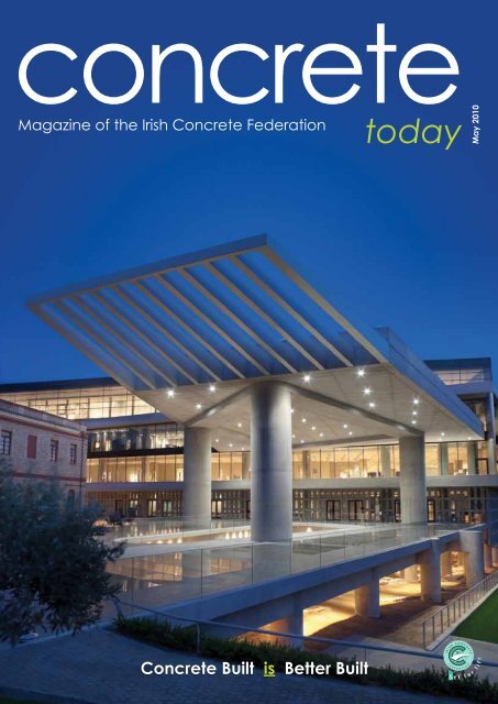
Secondly, we are featuring an article on <strong>the</strong> opening of <strong>the</strong> new Acropolis Museum in<br />
A<strong>the</strong>ns. This beautiful building, built predominantly in concrete and glass, is featured on<br />
<strong>the</strong> cover of our magazine. The building houses many of <strong>the</strong> ancient treasures of <strong>the</strong> nearby<br />
Par<strong>the</strong>non, views of which are afforded to visitors from <strong>the</strong> museum building. Unfortunately,<br />
and much to <strong>the</strong> dissatisfaction of <strong>the</strong> Greek authorities, <strong>the</strong> building houses only a few of <strong>the</strong><br />
Par<strong>the</strong>non Marbles, most of which are housed in <strong>the</strong> London Museum.<br />
Our third article with a Greek flavour concerns <strong>the</strong> manufacture of special Precast<br />
concrete cladding panels for <strong>the</strong> 2012 London Olympics. Ireland’s leading Precast cladding<br />
manufacturer, Techrete Ltd., recently won a contract to supply reconstructed stone cladding<br />
panels, to be erected on 26 blocks of apartments within <strong>the</strong> Olympic village. The apartments<br />
will house <strong>the</strong> Olympic athletes and a number of <strong>the</strong> Precast panels will feature friezes,<br />
depicting ancient Greek battles, centaurs etc. These frieze depictions were scanned by Techrete<br />
from <strong>the</strong> original Par<strong>the</strong>non friezes and reproduced at three times <strong>the</strong> original scale.<br />
Brian Ó’Murchú<br />
John Murphy - Obituary<br />
The staff and<br />
members of <strong>the</strong><br />
<strong>Irish</strong> <strong>Concrete</strong><br />
F e d e r a t i o n<br />
were greatly<br />
saddened to<br />
learn that our<br />
dear friend and<br />
colleague John<br />
A. Murphy, passed away on November 21st<br />
2009, following a short illness.<br />
Born and reared in Kildare town, John<br />
attended <strong>the</strong> De la Salle Primary and St.<br />
Josephs Academy Seondary School. Having<br />
qualified as an engineer in UCD he went on<br />
to work in many different areas, Roadstone,<br />
Kildare Co. Council, Q.K. Cold storage and<br />
finally setting up his own business Bracla<br />
in Newbridge Industrial Estate. In latter<br />
years John was appointed CEO of <strong>the</strong> <strong>Irish</strong><br />
Asphalt Pavement Producers Association<br />
(IAPA), whose office is located within <strong>the</strong><br />
<strong>Irish</strong> <strong>Concrete</strong> <strong>Federation</strong> office suite.<br />
John was a friend to all his colleagues,<br />
someone who listened attentively and<br />
offered advice if it was sought. He was<br />
a dedicated family man, who used his<br />
knowledge and drive to give his sons Brian<br />
and Alan and his daughter Caroline <strong>the</strong><br />
From <strong>the</strong> Editor<br />
best possible start in life. He was ever<br />
positive and cheerful and loved nothing<br />
better than to engage in banter with his<br />
friends and colleagues. He was always <strong>the</strong><br />
soul of <strong>the</strong> party.<br />
John had many passions in life, not least<br />
his undying support for <strong>the</strong> Kildare GAA<br />
team, whom he followed to every venue<br />
<strong>the</strong> length and breadth of <strong>the</strong> country.<br />
John also loved to play golf , though <strong>the</strong><br />
banter and laughter that went with it was<br />
more important to him than <strong>the</strong> golf itself.<br />
A gregarious character and man of action,<br />
John joined <strong>the</strong> Newbridge Credit Union<br />
in 1995 and later served as a Director and<br />
member of <strong>the</strong> Credit Committee. He was<br />
noted by his fellow committee members as<br />
a person who paid great attention to detail<br />
in making decisions and who always strived<br />
to be fair and compassionate in his dealings<br />
with o<strong>the</strong>rs.<br />
John was great company, a marvellous<br />
storyteller and brilliant raconteur. His<br />
wife Ann, his children and grandchildren<br />
were <strong>the</strong> mainstay of his life. The staff and<br />
members of <strong>the</strong> <strong>Irish</strong> <strong>Concrete</strong> <strong>Federation</strong><br />
offer our sincere condolences to his wife<br />
and family at this challenging time.<br />
ICF Staff<br />
ics awards<br />
<strong>Irish</strong> <strong>Concrete</strong><br />
Society Awards<br />
2009<br />
The winning entries at <strong>the</strong> <strong>Irish</strong> <strong>Concrete</strong><br />
Society’s Awards Evening, which<br />
took place recently, came from all over<br />
Ireland and ranged from private houses<br />
to community buildings to cable stayed<br />
bridges.<br />
This was <strong>the</strong> 28th Awards Evening and<br />
<strong>the</strong> event is always one of <strong>the</strong> highlights<br />
of <strong>the</strong> construction industry’s calendar.<br />
The Awards recognise excellence in both<br />
design and construction in concrete. The<br />
jury reviewed a total of twenty projects<br />
entered in three categories– Elemental,<br />
Infrastructure and Building, where <strong>the</strong>y<br />
were impressed by <strong>the</strong> quality and high<br />
standard of detail exhibited by all entries.<br />
They also considered suitable examples of<br />
<strong>the</strong> use of concrete in a sustainable context.<br />
The biennial Sculpture Award received 13<br />
high quality entries from all parts of <strong>the</strong><br />
country, each demonstrating <strong>the</strong> creative<br />
potential of concrete as a material. The<br />
annual Sean de Courcy Student Prize was<br />
also awarded on <strong>the</strong> night.<br />
Winner – Sustainability Award<br />
Fa<strong>the</strong>r Collins Park, Donaghmede<br />
The large park of 52 acres serves <strong>the</strong><br />
established area of Donaghmede and new<br />
housing developments stretching out to<br />
Belcamp, Belmayne and beyond.<br />
Fa<strong>the</strong>r Collins Park, Donaghmede<br />
concrete today<br />
2
concrete today - ics awards<br />
The park consists of shot-blast concrete<br />
paths and walkways, and a concrete<br />
skateboard park which is well-planned and<br />
detailed, and obviously well used. The jury<br />
noted that <strong>the</strong> ‘quality of <strong>the</strong> curved and<br />
angular shapes within <strong>the</strong> skate-park, and<br />
<strong>the</strong> innovation in <strong>the</strong>ir construction, are a<br />
credit to <strong>the</strong> Team and a challenge to <strong>the</strong><br />
skateboarders’. The concrete bridges which<br />
traverse <strong>the</strong> various watercourses are simple,<br />
well planned and well executed.<br />
These concrete elements which contain<br />
GGBS are combined with 5 eye-catching<br />
wind turbines that provide for <strong>the</strong> park’s<br />
lighting, water-pumps and aeration<br />
systems. There are a series of extensive<br />
watercourses including a surprising waterfeature.<br />
These clean hard materials are<br />
complimented by <strong>the</strong> use of some well<br />
planned soft landscaping. The free form<br />
wetland reed beds which purify <strong>the</strong> water<br />
mesh well with <strong>the</strong> park’s linear features,<br />
and also create a sustainable solution to <strong>the</strong><br />
lake and water features.<br />
Winner – Elemental Category<br />
Jigsaw, Dublin was winner in this category<br />
where 6 entries were considered.<br />
This project consists of a garden level<br />
single storey extension to <strong>the</strong> rear of a 2<br />
storey over garden level Victorian house in<br />
<strong>the</strong> inner Dublin suburbs. The extension<br />
is overlooked from <strong>the</strong> upper floors of <strong>the</strong><br />
existing house.<br />
The use of concrete allowed <strong>the</strong> architect<br />
create a floating tubular space with <strong>the</strong><br />
same material used in walls, floor and roof<br />
creating an interesting tension when viewed<br />
from <strong>the</strong> garden where this heavy element<br />
floats effortlessly over <strong>the</strong> garden terrace.<br />
The real success of <strong>the</strong> project was<br />
achieved by <strong>the</strong> excellent quality of <strong>the</strong><br />
insitu board marked concrete where<br />
concrete is exposed internally and<br />
externally. The execution was of such a<br />
high quality that <strong>the</strong> finished concrete was<br />
very even in colour and texture with little<br />
evidence of construction joints.<br />
Jigsaw, Dublin<br />
Winner – Infrastructural Category<br />
River Suir Bridge was <strong>the</strong> selected winner<br />
in a category of 7 entries.<br />
The bridge is a cable stayed bridge of<br />
total length 465 metres crossing <strong>the</strong> River<br />
Suir upstream of Waterford City. The<br />
imposing visual aspect is driven by <strong>the</strong> 112<br />
metre high concrete pylon in <strong>the</strong> shape of<br />
an inverted Y out of which 19 sets of four<br />
cables hang, giving an almost symmetrical<br />
form extending out from <strong>the</strong> concrete<br />
pylon.<br />
The pylon was constructed using an<br />
automatic climbing formwork system while<br />
<strong>the</strong> bridge deck is a horizontal steel frame<br />
supporting precast concrete panels.<br />
The jury noted that ‘<strong>the</strong> design of <strong>the</strong><br />
bridge has produced concrete and steel<br />
elements at a scale suitable to <strong>the</strong> overall<br />
structure and its setting. The relationship<br />
River Suir Bridge, Waterford<br />
of <strong>the</strong> concrete and steel is very well<br />
handled and <strong>the</strong> use of each recognises <strong>the</strong><br />
inherent character of each’.<br />
Overall Winner (Building Category)<br />
Visual Centre for Contemporary Art and<br />
George Bernard Shaw Theatre, Carlow.<br />
The Overall winner was in <strong>the</strong> Building<br />
Category where 7 entries were considered.<br />
This building is sited in <strong>the</strong> heart of<br />
Carlow town adjacent to Carlow Ca<strong>the</strong>dral<br />
and o<strong>the</strong>r historic buildings where <strong>the</strong> jury<br />
felt that ‘<strong>the</strong> concept of a glass box or jewel<br />
in a garden was most appropriate’.<br />
The success of <strong>the</strong> building is <strong>the</strong><br />
apparently effortless use of large elements,<br />
mainly concrete, in sympa<strong>the</strong>tic scale with<br />
<strong>the</strong> gallery spaces. The concrete elements<br />
have a textural scale of <strong>the</strong>ir own, such as<br />
<strong>the</strong> heavily ribbed slab soffits, <strong>the</strong> OSB<br />
board texture to <strong>the</strong> walls, which reads<br />
like wallpaper, smooth bands within<br />
<strong>the</strong> walls and <strong>the</strong> polished floors. The<br />
concrete walls are well co-ordinated and<br />
detailed especially at <strong>the</strong>ir base where no<br />
kickers were used and also at horizontal<br />
construction joints.<br />
The use of concrete in many forms and<br />
finish demonstrates <strong>the</strong> flexibility of <strong>the</strong><br />
material and <strong>the</strong> appropriateness of its use<br />
in such a civic building.<br />
This building has met and overcome<br />
many challenges, particularly in <strong>the</strong> use of<br />
concrete and is a worthy Winner of both<br />
<strong>the</strong> Building Category and <strong>the</strong> Overall <strong>Irish</strong><br />
<strong>Concrete</strong> Society Award for <strong>2010</strong>.<br />
concrete today<br />
3
concrete today - ics awards<br />
Project Team Details<br />
Overall (Building Category) – Visual Centre for Contemporary Art and<br />
George Bernard Shaw Theatre, Carlow<br />
Client:<br />
Carlow Local Authorities<br />
Engineer:<br />
ARUP Consulting Engineers<br />
Architect:<br />
Terry Pawson Architects<br />
Contractor:<br />
BAM Building<br />
Major Supplier:<br />
Durkan & Ryan<br />
Infrastructural Category – River Suir Bridge<br />
Client:<br />
Waterford City Council / NRA<br />
Engineer:<br />
ARUP Consulting Engineers<br />
Contractor:<br />
BAM / Dragados JV<br />
Major Supplier:<br />
Roadstone / Banagher <strong>Concrete</strong><br />
Elemental Award – Jigsaw, Dublin<br />
Client:<br />
Private<br />
Engineer:<br />
Kavanagh Mansfield & Partners<br />
Architect:<br />
McCullough Mulvin Architects<br />
Contractor:<br />
Patrick Brock & Sons<br />
Major Supplier:<br />
Roadstone<br />
Sustainability Award – Fa<strong>the</strong>r Collins Park<br />
Client:<br />
Dublin City Council<br />
Engineer:<br />
O’Connor Sutton Cronin<br />
Architect:<br />
Ar Arq Ireland<br />
Contractor:<br />
Liffey Developments<br />
Major Supplier:<br />
Goode <strong>Concrete</strong> / Bromac Construction / Erlin<br />
CHANGES<br />
occasion was very powerful and memorable.<br />
We commend <strong>the</strong> artist for his crafting - <strong>the</strong><br />
expert modelling that brings so much life to<br />
<strong>the</strong> work and, by choosing to use standard<br />
grey concrete, resisting <strong>the</strong> temptation to<br />
prettify <strong>the</strong> work.”<br />
“On a technical level this work brings <strong>the</strong><br />
use of concrete into new territory. On an<br />
artistic level it is work of true originality and<br />
integrity.”<br />
Visual Centre for<br />
Contemporary Art and<br />
George Bernard Shaw<br />
Theatre, Carlow<br />
Sean De Courcy Student Award<br />
This is an award given to <strong>the</strong> best final-year<br />
project on a concrete-related topic from<br />
<strong>the</strong> engineering faculties of <strong>the</strong> third level<br />
institutions.<br />
The award is named after <strong>the</strong> late Sean<br />
de Courcy, an inspirational professor for<br />
many years at UCD, a former chairman of<br />
<strong>the</strong> <strong>Irish</strong> <strong>Concrete</strong> Society and author and<br />
historian of note.<br />
The winner of <strong>the</strong> <strong>Irish</strong> <strong>Concrete</strong><br />
Society Sean De Courcy Student award<br />
for 2009 is Stephen Cunningham of<br />
TCD for ‘Influence of Aggregate Size on<br />
Shear Capacity of non-Shear Reinforced<br />
<strong>Concrete</strong> Beams and Implications for<br />
Crack Slide Theory’.<br />
The project topic is very relevant in<br />
terms of analysis of older structures and<br />
sustainability – preserving structures that<br />
might o<strong>the</strong>rwise have to be demolished.<br />
The jury also found that <strong>the</strong> objectives of<br />
<strong>the</strong> project were achieved.<br />
The research was thorough, <strong>the</strong><br />
experimental work was comprehensive and<br />
correctly analysed and <strong>the</strong> entire project was<br />
well presented in a clear logical manner.<br />
Sculpture Award<br />
‘CHANGES’ by Kenneth Lambert is this<br />
years ICS sculpture award. It is a wallmounted<br />
artwork, a kind of painting, cast<br />
in concrete and resin. It measures about 2.5<br />
metres by 1.2 metres and about 150mm<br />
thick. It is made up of three interlocking<br />
curved panels. The side panels are cast in<br />
concrete and depict, in low relief, <strong>the</strong> artist<br />
and his bro<strong>the</strong>rs in a car returning from<br />
his mo<strong>the</strong>r’s funeral. The central panel, in<br />
contrast, is cast in clear resin.<br />
The jury noted:<br />
“There is so much about this work that we<br />
found immediately engaging and compelling.<br />
It challenged our pre-conceptions about <strong>the</strong><br />
use of concrete. Familiar as we are to <strong>the</strong><br />
use of concrete in buildings or larger scale<br />
public sculpture – it was extraordinary to<br />
see it used in this picture that expresses such<br />
an emotional atmosphere. The evocation,<br />
depicted in concrete, of <strong>the</strong> solemnity of <strong>the</strong><br />
Winner’s presentation names as follows; Front row left to right; Tim Madden (Carlow<br />
Local Authorities), Carissa Farrell (Visual Centre for Contemporary Art & George<br />
Bernard Shaw Theatre), Aidan O’Connell (BAM Building), Seamus Maguire (Durkan &<br />
Ryan), Ian Roberts (ARUP)<br />
Back Row left to right; Eddie O’ Brien (BAM Building), Garry Dodds (ARUP), Joe Watters<br />
(Carlow Local Authorities), Hugh Gray (ARUP), Mark Richardson (Chairman, <strong>Irish</strong><br />
<strong>Concrete</strong> Society), Michael Gillen (BAM Building), Eddie Ryan (Durkan & Ryan), Joe<br />
Flavin (VIisual Centre for Contemporary Art and George Bernard Shaw Theatre)<br />
concrete today<br />
4
concrete today - designing for earthquake - precast concrete<br />
Designing for Earthquake – Precast <strong>Concrete</strong><br />
The Importance of <strong>the</strong> conceptual design of precast concrete structures in<br />
seismic areas and lessons from past earthquakes – The SAFECAST Programme<br />
By Georgia Kremmydia, National Technical University of A<strong>the</strong>ns, A<strong>the</strong>ns, Greece<br />
Dipl. Civil Engineer, PhD Candidate<br />
Introduction<br />
In recent years, <strong>the</strong>re has been a sharp<br />
increase in <strong>the</strong> use of prefabricated, offsite<br />
construction techniques, including<br />
Precast concrete. Prefabricated elements,<br />
such as architectural cladding panels,<br />
Precast hollowcore and wideslab floors and<br />
stair flights are also being introduced to<br />
buildings which are primarily constructed<br />
insitu. A shortage of site operatives, <strong>the</strong><br />
need to eliminate uncertainty in <strong>the</strong><br />
programme caused by inclement wea<strong>the</strong>r<br />
conditions and <strong>the</strong> general requirement for<br />
fast, reliable and economic construction<br />
techniques are among <strong>the</strong> main drivers.<br />
Joints and Connections<br />
As is well known, <strong>the</strong> main difference<br />
between traditional, monolithic castinsitu<br />
R.C. structures and corresponding<br />
prefabricated structures, is that <strong>the</strong><br />
latter are composed of several bearing<br />
members cast in a factory ra<strong>the</strong>r than on<br />
site; <strong>the</strong>refore <strong>the</strong> structure is composed<br />
of a set of ‘elements’ which are joined by<br />
‘connections’. Thus <strong>the</strong> main structural<br />
issue in Precast construction relates to <strong>the</strong><br />
connections between Precast members<br />
and to <strong>the</strong> extent to which connections<br />
affect <strong>the</strong> response of <strong>the</strong> total structure<br />
under seismic actions. In this regard, <strong>the</strong><br />
need for Precast structures to satisfy <strong>the</strong><br />
fundamental structural requirements of<br />
‘non collapse’ and ‘damage limitation’ ,<br />
L’Aquila earthquake central Italy 2009<br />
caption<br />
L’Aquila earthquake central Italy 2009<br />
under design-earthquake conditions needs<br />
to be carefully studied.<br />
Experience based on <strong>the</strong> history of seismic<br />
engineering and recent experience of <strong>the</strong><br />
seismic behaviour of R.C. structures, showed<br />
that in spite of <strong>the</strong> enormous development<br />
of computer simulation software, <strong>the</strong><br />
satisfaction of <strong>the</strong> fundamental requirements<br />
under <strong>the</strong> design-earthquake cannot solely<br />
be achieved by means of calculations and<br />
that several basic design concepts proved to<br />
be more important.<br />
Structural simplicity and uniformity<br />
Among <strong>the</strong> most important of <strong>the</strong>se design<br />
concepts is <strong>the</strong> concept of ‘structural<br />
simplicity’ as characterised by ‘uniformity’,<br />
‘symmetry’ and ‘regularity’ in <strong>the</strong><br />
configuration of <strong>the</strong> structural systems in<br />
plan and/or, elevation. This concept should<br />
be addressed in <strong>the</strong> first step of <strong>the</strong> design<br />
process, namely ‘conceptual design’. That<br />
is to say, every analysis has to be carried out<br />
on a preconceived structural scheme.<br />
In fact, by simplifying <strong>the</strong> structural<br />
system, clear and direct paths (including<br />
alternative paths) for <strong>the</strong> transmission of<br />
<strong>the</strong> seismic loads should also be ensured.<br />
In this way, <strong>the</strong> modelling, analysis,<br />
dimensioning and detailing of <strong>the</strong> structure<br />
is subject to less uncertainty and thus <strong>the</strong><br />
prediction of seismic behaviour is much<br />
more reliable.<br />
The ‘in plan regularity’ is primarily a<br />
function of <strong>the</strong> geometrical configuration<br />
of <strong>the</strong> building: <strong>the</strong> configuration should<br />
be compact and clear. In plan set-backs<br />
(re-entrant corners or edge recesses) or L,<br />
n, E or - L shapes etc. should be avoided,<br />
or o<strong>the</strong>rwise limited and specially treated.<br />
• The ratio of Lmax: Lmin. should not be<br />
less than 4<br />
• The distribution of <strong>the</strong> lateral stiffness<br />
concrete today<br />
5
concrete today - designing for earthquake - precast concrete<br />
L’Aquila earthquake central Italy 2009<br />
and <strong>the</strong> mass should be closely<br />
symmetrical in plan with respect to two<br />
orthogonal axes<br />
• In this respect, if necessary, uniformity<br />
may be realised by subdividing <strong>the</strong> entire<br />
building by means of seismic joints into<br />
dynamic independent units, provided<br />
that <strong>the</strong>se joints are designed against<br />
pounding of <strong>the</strong> individual units<br />
• Uniformity in <strong>the</strong> development of<br />
<strong>the</strong> structure along <strong>the</strong> height of <strong>the</strong><br />
building is also important and can be<br />
achieved when:<br />
• Almost all lateral resisting systems<br />
such as cores, structural walls or<br />
columns in frame systems, run without<br />
interruption from <strong>the</strong>ir foundations to<br />
<strong>the</strong> top of <strong>the</strong> building<br />
• Both <strong>the</strong> lateral stiffness and <strong>the</strong> mass of<br />
<strong>the</strong> individual storeys remain constant<br />
or reduce gradually and<br />
• A natural flow of forces is ensured by<br />
avoiding staggered beams or (worse)<br />
staggered columns<br />
• O<strong>the</strong>r basic principles to be satisfied<br />
by a sound conceptual design are<br />
<strong>the</strong> bi-directional resistance, torsion<br />
resistance and stiffness<br />
Horizontal actions<br />
The structure must be made to resist<br />
horizontal actions in any direction. This<br />
can be achieved by arranging all structural<br />
elements (columns and/or walls) in an<br />
orthogonal in-plan structural pattern<br />
e.g. by distributing those close to <strong>the</strong><br />
periphery of <strong>the</strong> building, ensuring similar<br />
resistance and stiffness characteristics in<br />
both main directions and limiting possible<br />
torsional motions which tend to stress <strong>the</strong><br />
different structural elements in a nonuniform<br />
way. In all cases, special attention<br />
must be paid to <strong>the</strong> position of <strong>the</strong><br />
elevators and staircases into <strong>the</strong> structural<br />
system.<br />
Soil, structure interaction<br />
In seismic areas, <strong>the</strong> interaction of <strong>the</strong> soil<br />
with <strong>the</strong> superstructure must be carefully<br />
studied. In general, <strong>the</strong> configuration of <strong>the</strong><br />
foundation relative to <strong>the</strong> superstructure<br />
should be such as to ensure that <strong>the</strong> whole<br />
building is subjected to a uniform seismic<br />
excitation.<br />
L’Aquila earthquake central Italy 2009<br />
Secondary structural elements and<br />
cladding panels<br />
Moreover, when designing precast<br />
structures where secondary elements such<br />
as infills/partition walls/claddings etc.<br />
are envisaged, special attention must be<br />
given to arranging <strong>the</strong>m symmetrically in<br />
plan, to avoid all possible irregularities in<br />
a strong seismic event. Generally, all of <strong>the</strong><br />
aforementioned secondary elements must<br />
be connected with <strong>the</strong> structural elements<br />
in a way that <strong>the</strong>y will not disturb <strong>the</strong><br />
predicted seismic response of <strong>the</strong> structure<br />
and that <strong>the</strong>y will not partially or totally<br />
collapse. Based on experience from past<br />
earthquakes (e.g. earthquake at L’aquilla,<br />
Italy 2009) it has become obvious once<br />
again that inadequate connection details<br />
between cladding panels and <strong>the</strong> structural<br />
panels can lead to out-of-plane collapse<br />
of <strong>the</strong>se cladding panels during a seismic<br />
event, with considerable risk to human life.<br />
The Development of Codes<br />
Experience from <strong>the</strong> past has shown<br />
repeatedly that construction techniques<br />
of every type preceded any <strong>the</strong>oretical<br />
and experimental scientific progress and<br />
relevant codes, since complete code-bodies<br />
governing <strong>the</strong> design and construction<br />
of structures and especially of Precast<br />
structures under seismic conditions, did<br />
not exist in <strong>the</strong>ir current organised form. In<br />
cases where basic code-bodies had formed,<br />
<strong>the</strong>y did not reflect <strong>the</strong> more recent aspects<br />
of Earthquake Resistant Design Philosophy<br />
such as ductility demand, capacity design<br />
rules and o<strong>the</strong>r such factors. Also, in some<br />
concrete today<br />
6
concrete today - designing for earthquake - precast concrete<br />
cases of mass construction of Precast<br />
structures, speed of construction and low<br />
cost featured more as design considerations,<br />
ra<strong>the</strong>r than ‘conceptual design aspects’<br />
which would contribute to increased safety<br />
against earthquakes, even taking into<br />
account <strong>the</strong> more limited level of scientific<br />
knowledge at that time.<br />
In this respect, <strong>the</strong> case of <strong>the</strong> Armenia<br />
earthquake of 1989 is worth mentioning<br />
in which, among o<strong>the</strong>r damage, two<br />
cities in particular, Leminakan and<br />
Spitak which were built extensively using<br />
prefabrication techniques were completely<br />
destroyed. According to <strong>the</strong> findings of <strong>the</strong><br />
International Scientific Community, <strong>the</strong><br />
extent of <strong>the</strong> disaster was not due to <strong>the</strong> use<br />
of prefabrication itself but, much more due<br />
to completely inefficient design concepts,<br />
e.g. lack of proper lateral resisting systems,<br />
very bad detailing of Precast members<br />
and <strong>the</strong>ir connections and finally very bad<br />
quality of <strong>the</strong> concrete and improper use<br />
of steel.<br />
Such cases and o<strong>the</strong>r cases of collapse of<br />
Precast structures after strong earthquakes<br />
in <strong>the</strong> past (Kocaeli earthquake 1999,<br />
Northridge earthquake 1994, Vrancea<br />
earthquake 1977 etc), gave <strong>the</strong> ra<strong>the</strong>r<br />
unjustified impression to <strong>the</strong> international<br />
community that Precast concrete<br />
constructions performed poorly under seismic<br />
actions due to <strong>the</strong> fact that prefabrication was<br />
used.<br />
Findings of International Scientific<br />
Community<br />
Never<strong>the</strong>less, according to <strong>the</strong> findings of<br />
<strong>the</strong> International Scientific Community,<br />
it is a fact that <strong>the</strong>re are many examples of<br />
excellent behaviour of Precast structures, if<br />
properly designed and constructed in a way<br />
which takes into account <strong>the</strong> fundamental<br />
requirements of non-collapse and damage<br />
limitation, within acceptable cost limits. In<br />
this respect it is worth mentioning that <strong>the</strong><br />
only buildings which survived <strong>the</strong> strong<br />
earthquake motions in one of <strong>the</strong> above<br />
mentioned two cities of Armenia were some<br />
multi-storey large-panel buildings which<br />
were designed and constructed, taking into<br />
account basic conceptual design aspects.<br />
L’Aquila earthquake central Italy 2009<br />
Considerable research has been reported<br />
worldwide in <strong>the</strong> last decades due to <strong>the</strong><br />
work of individual companies and by<br />
relevant institutions, which has contributed<br />
to <strong>the</strong> reliability of Precast structures<br />
built in seismic regions. Among <strong>the</strong>m <strong>the</strong><br />
PRESS (Precast Seismic Structural System)<br />
research programme carried out by <strong>the</strong><br />
USA and Japan may be considered <strong>the</strong><br />
most notable experimental investigation<br />
of <strong>the</strong> response of Precast structures to<br />
earthquake. Through this research project,<br />
new concepts and technologies have<br />
been invented and experimentally and<br />
<strong>the</strong>oretically supported, using innovative<br />
connections and prestressing.<br />
The SAFECAST Programme<br />
In March 2009, a new European<br />
Research Programme was initiated,<br />
entitled SAFECAST – Performance of<br />
innovative mechanical connections in<br />
Precast building structures under seismic<br />
conditions’ , financed under <strong>the</strong> 7th<br />
L’Aquila earthquake central Italy 2009<br />
Framework Programme ‘Research for<br />
Small and Medium Enterprises (SME)<br />
Associations action’. The project derives<br />
from two previous research projects, <strong>the</strong><br />
ECOLEDER and <strong>the</strong> PRECAST EC8<br />
project and completes <strong>the</strong>m thoroughly.<br />
Both of <strong>the</strong>se projects dealt with <strong>the</strong><br />
seismic behaviour and ductility capacity<br />
of Precast concrete structures compared<br />
to corresponding cast insitu structures.<br />
However, it was clear from <strong>the</strong> findings<br />
that <strong>the</strong> actual design of <strong>the</strong> connections<br />
was not fully covered and <strong>the</strong>refore<br />
difficult to be modelled properly for<br />
<strong>the</strong> numerical studies used in <strong>the</strong> design<br />
of Precast building structures. Thus,<br />
SAFECAST has been established to<br />
investigate, both experimentally and<br />
numerically, <strong>the</strong> seismic behaviour of<br />
several types of connections between<br />
Precast members. The success of this<br />
project is critical to <strong>the</strong> design of Precast<br />
concrete structures, as reliable as cast<br />
insitu concrete structures.<br />
concrete today<br />
7
concrete today - precast schools solution<br />
Fast-track Precast Schools Solution<br />
High quality school building in just 20 weeks<br />
Project: Flemington National School,<br />
Balbriggan, Co. Dublin<br />
A high quality precast concrete school can be delivered in 20 weeks. With <strong>the</strong> combined<br />
experience of builders Sammon Contractors and <strong>the</strong> Concast Precast Group, a quality<br />
school solution has been provided at Flemington in Balbriggan, which will be ready<br />
well in advance of <strong>the</strong> September opening date. The more robust Precast building will<br />
greatly outperform alternative light-weight solutions, in terms of fire performance, sound<br />
performance and <strong>the</strong> overall durability of <strong>the</strong> structure. In particular <strong>the</strong> danger of <strong>the</strong><br />
ignition of <strong>the</strong> structure by vandals during <strong>the</strong> construction phase is overcome by <strong>the</strong> use of<br />
completely non-combustible Precast concrete elements.<br />
Front Elevation Flemington School Balbriggan<br />
The Department of Education has<br />
recently approved a fur<strong>the</strong>r seven new<br />
primary schools which are due to open<br />
next September. The substantial building<br />
programme proposed by <strong>the</strong> Department<br />
is being rolled out on foot of demographic<br />
studies which suggest that <strong>the</strong> school going<br />
population will rise sharply in <strong>the</strong> coming<br />
years. One such project is <strong>the</strong> new 18<br />
classroom Flemington National School,<br />
which is located in Balbriggan County<br />
Dublin, in a rapidly developing area.<br />
Sammon Contracting, headquartered<br />
in Kilcock, Co. Kildare and with offices<br />
in London, Dubai, Abu Dhabi and<br />
Tripoli, are a global provider of social<br />
infrastructure, with a particular strength<br />
in design & build of schools and colleges.<br />
Sammon is accredited with ISO 9001,<br />
ISO 14001 and OHSAS 18001 and<br />
are founding member of Buildsafe<br />
UAE, now <strong>the</strong> cornerstone Health and<br />
Safety organisation in <strong>the</strong> Middle East.<br />
Sammon Contracting have put toge<strong>the</strong>r<br />
a Precast concrete solution which can<br />
deliver a complete Precast concrete 18<br />
classroom school in a 20 week period.<br />
Precast concrete schools provide superior<br />
Precast Panels by <strong>the</strong> Concast Precast Group<br />
concrete today<br />
8
concrete today - precast schools solution<br />
performance in terms of <strong>the</strong> durability of<br />
<strong>the</strong> structure and <strong>the</strong> low-maintenance<br />
requirements over <strong>the</strong> life-span of <strong>the</strong><br />
building. The solid, high density wall units,<br />
which have only a small number of joints,<br />
have greater air-tightness and <strong>the</strong>refore<br />
greater <strong>the</strong>rmal and sound reduction<br />
properties.<br />
Sammon Contracting have an impressive<br />
track record in <strong>the</strong> current schools<br />
programme and have recently completed<br />
projects in Tullamore, Mornington,<br />
Kinnegad, Drogheda, Middleton and<br />
Gorey. Concast were selected to design,<br />
manufacture and install <strong>the</strong> Precast<br />
concrete frame at Flemington, Balbriggan.<br />
The Concast Precast Group, were<br />
appointed in December 2009, to provide<br />
a complete Precast concrete frame.<br />
Concast are focused on competitiveness<br />
through quality, supported by <strong>the</strong>ir quality<br />
management systems ISO 9001:2008.<br />
The design team consisted of DBFL<br />
Consulting Engineers and McCarthy<br />
O’Hora Associates. The designers opted<br />
for <strong>the</strong> Precast option for a variety of<br />
reasons, not least <strong>the</strong> quality of finish,<br />
speed on site and <strong>the</strong> reduction in <strong>the</strong><br />
number of follow on trades and wet<br />
processes. The selection of an off-site,<br />
factory production process was fortuitous<br />
as it transpired that temperatures in early<br />
January <strong>2010</strong> fell to as low as -10°C. A<br />
construction process involving insitu<br />
concrete would almost certainly have led to<br />
a delay in <strong>the</strong> construction programme. In<br />
<strong>the</strong> event, all Precast units were produced<br />
in a quality controlled environment and<br />
were delivered to site as per <strong>the</strong> building<br />
programme.<br />
The new Flemington school consists of<br />
18 large open plan classrooms, with activity<br />
areas, multi media rooms, and teachers<br />
lounge. The design includes particular<br />
focus on energy issues with <strong>the</strong> objective<br />
of achieving energy performance levels<br />
approaching ‘passive building’ standards.<br />
The use of Precast concrete panels to form<br />
attic spaces, with steel rafters connected<br />
directly to <strong>the</strong> top of <strong>the</strong> sloping panels,<br />
enhances security and provides greatly<br />
improved internal fire compartmentation.<br />
The incorporation of cast-in items, such<br />
as recesses and Halfen channels, facilitates<br />
follow on trades and reduces <strong>the</strong> need<br />
for ladders and drilling on site, which<br />
is desirable from a Health and Safety<br />
perspective.<br />
The Precast wall panels were installed<br />
over a five week period, at a rate of 18<br />
panels per day (i.e. averaging over 500sq/m<br />
of wall panels per day). Concast’s justin-time<br />
delivery capabilities and <strong>the</strong><br />
array of efficiencies inherent in Precast,<br />
create a speed advantage throughout <strong>the</strong><br />
construction process, saving costs and<br />
meeting deadlines.<br />
T h e c o m p o n e n t s w h i c h w e r e<br />
manufactured at Concast’s plant in<br />
Newcastle West Dublin, include:<br />
• both non load-bearing and load-bearing<br />
precast concrete panels<br />
• hollowcore and wideslab floor/ceiling<br />
planks<br />
• precast columns and beams<br />
A total precast concrete system saves<br />
money in many ways, both in <strong>the</strong> short and<br />
long-term. When using precast structures,<br />
several trades and materials are eliminated<br />
from <strong>the</strong> construction process. The savings<br />
include costs often hidden within overall<br />
construction budgets and create advantages<br />
that continue to save throughout <strong>the</strong><br />
building’s lifetime. These life-cycle savings<br />
help control operational budgets, resulting<br />
in lower construction costs today and a<br />
reduced public tax burden in <strong>the</strong> longer<br />
term.<br />
The approach and quality of work<br />
now being applied to projects such as<br />
Flemington in Balbriggan, will ensure<br />
that schoolchildren and teachers alike will<br />
be provided with <strong>the</strong> best educational<br />
environment in which to learn and work.<br />
Project Team<br />
ECAP, prefinished external insulation fixed to precast<br />
cladding panel as supplied by Pro<strong>the</strong>rm<br />
Client:<br />
Department of Education & Skills<br />
Project Managers:<br />
KSN Project Management<br />
Developer/Contractor:<br />
Sammon Contracting<br />
Architect:<br />
McCarthy O’Hora Associates<br />
Consulting Engineers:<br />
DBFL<br />
M&E Consultants:<br />
Semple McKillop<br />
Precast Structural Frame:<br />
Concast Precast Group<br />
Health & Safety:<br />
Safety Solutions<br />
concrete today<br />
9
concrete today - techrete - olympic village, london 2012<br />
Techrete - Olympic Village, London 2012<br />
Techrete Reproduces <strong>the</strong> Par<strong>the</strong>non Marbles<br />
concrete today<br />
10
concrete today - techrete - olympic village, london 2012<br />
Precast Cladding Panels by Techrete Ltd.<br />
Ireland’s leading Precast concrete panel<br />
manufacturer, Techrete Ltd., is currently<br />
involved in <strong>the</strong> construction of apartment<br />
buildings in London’s Olympic village. The<br />
village will house <strong>the</strong> Olympic athletes for<br />
<strong>the</strong> 2012 Olympics and will comprise a<br />
series of mansion blocks, each containing<br />
6 to 7 buildings, arranged in courtyard<br />
formation and varying in height from eight<br />
to twelve stories. Techrete were chosen as<br />
<strong>the</strong> Precast panel manufacturers, for four<br />
mansion blocks primarily on <strong>the</strong> basis that<br />
<strong>the</strong> company could demonstrate <strong>the</strong> ability<br />
to deal with <strong>the</strong> challenges posed by <strong>the</strong><br />
project, in particular its complexity and tight<br />
programme and logistics.<br />
The project posed a fur<strong>the</strong>r unusual<br />
challenge, in that <strong>the</strong> Architects specification<br />
required that two of <strong>the</strong> buildings should be<br />
clad in reconstructed stone panels, faced in<br />
frieze type images, replicated from 5 of <strong>the</strong><br />
famous Par<strong>the</strong>non Marbles (see text in side<br />
panel) <strong>the</strong> majority of which are currently<br />
housed in <strong>the</strong> British Museum. The<br />
architects selected <strong>the</strong>se images specifically<br />
to reflect <strong>the</strong> Greek origins and invoke <strong>the</strong><br />
ancient spirit of <strong>the</strong> Games.<br />
Replicating <strong>the</strong> images from <strong>the</strong><br />
Par<strong>the</strong>non Marbles posed a significant<br />
challenge which was eventually resolved by<br />
<strong>the</strong> use of scanning technology. The use of<br />
this technology negated <strong>the</strong> need for casts<br />
Precast Cladding Panels<br />
by Techrete Ltd.<br />
to be taken, which could potentially have<br />
caused damage to <strong>the</strong> marbles and <strong>the</strong>refore<br />
was not a viable option. The Scanning<br />
equipment produced 3-D image files which<br />
were <strong>the</strong>n transferred to a CNC (5 axis)<br />
routing machine to create a positive MDF<br />
(wooden) carved copy of <strong>the</strong> originals, from<br />
which rubber moulds were produced to<br />
cast <strong>the</strong> reconstructed stone panels. This<br />
was a complicated process which required<br />
approvals at all stages and a high degree of<br />
technical expertise.<br />
Precast Cladding Panels<br />
by Techrete Ltd.<br />
The architect’s specification required<br />
that <strong>the</strong> frieze images be replicated at three<br />
times <strong>the</strong> scale of <strong>the</strong> original marbles. The<br />
use of digital technology facilitated this<br />
aspect of <strong>the</strong> specification. Ano<strong>the</strong>r aspect<br />
of <strong>the</strong> reproduction is that all elements of<br />
<strong>the</strong> frieze images which could act as rain<br />
shelves were filled-in (in <strong>the</strong> construction of<br />
<strong>the</strong> mould). This however does not detract<br />
from <strong>the</strong> appearance, since <strong>the</strong> panels<br />
are generally viewed from <strong>the</strong> underside<br />
(looking upwards) and <strong>the</strong>refore <strong>the</strong> three<br />
dimensional appearance is retained.<br />
The use of frieze panels in modern<br />
buildings is rare and this is due in part to<br />
<strong>the</strong> influence of <strong>the</strong> modern movement in<br />
WHAT ARE THE<br />
PARTHENON MARBLES?<br />
When <strong>the</strong> Par<strong>the</strong>non was built between<br />
447BC and 432BC, three sets of<br />
sculptures, <strong>the</strong> metopes, <strong>the</strong> frieze and<br />
<strong>the</strong> pediments, were created to adorn it.<br />
Of <strong>the</strong>se, <strong>the</strong> metopes and <strong>the</strong> frieze were<br />
part of <strong>the</strong> structure of <strong>the</strong> Par<strong>the</strong>non<br />
itself. They were not carved first<br />
and <strong>the</strong>n put in place, high up on <strong>the</strong><br />
Par<strong>the</strong>non, but were carved on <strong>the</strong> sides<br />
of <strong>the</strong> Par<strong>the</strong>non itself after it had been<br />
constructed.<br />
The metopes were individual sculptures<br />
in high relief. There were 92 metopes, 32<br />
on each side and 14 at each end and each<br />
metope was separated from its neighbours<br />
by a simple architectural decoration called<br />
a triglyph. The metopes were placed<br />
around <strong>the</strong> building, above <strong>the</strong> outside<br />
row of columns and showed various<br />
mythical battles. The North side showed<br />
scenes from <strong>the</strong> Trojan war; <strong>the</strong> South<br />
side showed a battle between <strong>the</strong> Greeks<br />
and <strong>the</strong> Centaurs - part man, part horse;<br />
<strong>the</strong> East side showed <strong>the</strong> Olympian gods<br />
fighting giants and <strong>the</strong> West side showed<br />
a battle between Greeks and Amazons.<br />
The frieze, 160 metres long, was placed<br />
above <strong>the</strong> inner row of columns, so it was<br />
not so prominently displayed. It is one<br />
long, continuous sculpture in low relief,<br />
showing <strong>the</strong> procession to <strong>the</strong> temple at<br />
<strong>the</strong> Pana<strong>the</strong>naic festival.<br />
Not all of <strong>the</strong> Par<strong>the</strong>non Marbles,<br />
however, survive down to <strong>the</strong> present<br />
day. There were originally 115 panels<br />
in <strong>the</strong> frieze. Of <strong>the</strong>se, ninety-four still<br />
exist, ei<strong>the</strong>r intact or broken. Thirty six<br />
are in A<strong>the</strong>ns, fifty-six are in <strong>the</strong> British<br />
Museum and one is in <strong>the</strong> Louvre. Of<br />
<strong>the</strong> original ninety two metopes, thirtynine<br />
are in A<strong>the</strong>ns and fifteen are in<br />
London. Seventeen pedimental statues,<br />
including a caryatid and a column from<br />
<strong>the</strong> Erech<strong>the</strong>ion are also in <strong>the</strong> British<br />
Museum. So <strong>the</strong> Par<strong>the</strong>non Marbles are<br />
almost equally divided, half in London<br />
and half in A<strong>the</strong>ns.<br />
architecture, which rejected all forms of<br />
ornamentation. A more relaxed attitude has<br />
developed in recent times, and although<br />
designers continue to successfully produce<br />
pure forms, <strong>the</strong>re is also recognition that<br />
<strong>the</strong>re is room in some instances for a more<br />
‘human’ architecture.<br />
The advanced panel manufacturing<br />
methods used by Techrete in <strong>the</strong> Olympic<br />
village has broader applications, and could<br />
be used to depict scenes from Celtic lore<br />
(for example) for use in Precast school<br />
buildings or indeed industrial buildings.<br />
concrete today<br />
11
concrete today - acropolis museum<br />
The New Acropolis Museum<br />
Introduction<br />
The New Acropolis Museum is <strong>the</strong><br />
result of an architectural competition<br />
which was announced in 2001. The<br />
competition winners, Bernard Tschumi<br />
Architects, and a range of consultants<br />
(see credits) were appointed in September<br />
2001 and <strong>the</strong> design completed in August<br />
2002. Construction began in 2003 and<br />
<strong>the</strong> building phase was completed in<br />
September 2007. Following <strong>the</strong> transfer of<br />
artefacts, <strong>the</strong> museum was opened to <strong>the</strong><br />
public in June 2009. The project was by<br />
co-financed by <strong>the</strong> Hellenic Republic and<br />
<strong>the</strong> European Regional Development Fund<br />
(ERDF)<br />
Although <strong>the</strong>re are some local reservations<br />
as to <strong>the</strong> scale of <strong>the</strong> building, which is<br />
located adjacent to a residential area, <strong>the</strong>re<br />
is general agreement that it is a structure<br />
worthy of <strong>the</strong> many priceless artefacts, of<br />
world significance which are on display. The<br />
museum is home to copies of <strong>the</strong> renowned<br />
Par<strong>the</strong>non Marbles – marble friezes<br />
Caryatids erech<strong>the</strong>oin<br />
Precast concrete cladding panels<br />
removed from <strong>the</strong> face of <strong>the</strong> Par<strong>the</strong>non.<br />
Controversially, many of <strong>the</strong> original friezes<br />
(also known as <strong>the</strong> Elgin Marbles) are<br />
housed in <strong>the</strong> London History Museum.<br />
From an <strong>Irish</strong> Perspective, it is difficult to<br />
look at <strong>the</strong> exposed ancient ruins, cleverly<br />
housed under <strong>the</strong> new structure, supported<br />
photographs by Nikos Daniilidis<br />
on pilotis and partially exposed to <strong>the</strong> open<br />
air, without reflecting on ‘what might<br />
have been’, on Dublin’s Wood Quay. The<br />
building is largely constructed in reinforced<br />
concrete and glass, with precast concrete<br />
and some steel elements featuring in various<br />
parts of <strong>the</strong> structure.<br />
Architects Description - Text<br />
Bernard Tschumi Architects<br />
Gallery area<br />
Site<br />
Located in <strong>the</strong> historic area of Makryianni,<br />
<strong>the</strong> Museum stands some 300 meters<br />
(980feet) Sou<strong>the</strong>ast of <strong>the</strong> Par<strong>the</strong>non.<br />
The top floor (Par<strong>the</strong>non Gallery)<br />
offers a 360-degree panoramic view of<br />
<strong>the</strong> Acropolis and modern A<strong>the</strong>ns. The<br />
Museum is entered from <strong>the</strong> Dionysios<br />
Areopagitou pedestrian street, which<br />
links it to <strong>the</strong> Acropolis and o<strong>the</strong>r key<br />
archeological sites in A<strong>the</strong>ns.<br />
Programme<br />
With exhibition space of more than<br />
14,000 square meters (150,000 square<br />
concrete today<br />
12
concrete today - acropolis museum<br />
feet) and a full range of modern visitor<br />
amenities, <strong>the</strong> New Acropolis Museum<br />
will tell <strong>the</strong> complete story of life on <strong>the</strong><br />
A<strong>the</strong>nian Acropolis and its surroundings.<br />
It will do so by uniting collections that are<br />
currently dispersed in multiple institutions,<br />
including <strong>the</strong> outdated Acropolis Museum<br />
(built in <strong>the</strong>19th century with gallery space<br />
of 1,450 square meters, or 15,500 square<br />
feet). The rich collections will provide<br />
visitors with a comprehensive picture of<br />
<strong>the</strong> human presence on <strong>the</strong> Acropolis,<br />
from pre-historic times through late<br />
Antiquity. Integral to this program is <strong>the</strong><br />
display of an archaeological excavation on<br />
<strong>the</strong> site of <strong>the</strong> Museum itself: ruins from<br />
<strong>the</strong> 4th through 7th centuries A.D., left<br />
intact and protected beneath <strong>the</strong> building<br />
and made visible through <strong>the</strong> first floor.<br />
O<strong>the</strong>r program facilities include a 200-seat<br />
auditorium.<br />
Archaeological excavation<br />
Par<strong>the</strong>non friezes gallery area<br />
of museum. Light for <strong>the</strong> exhibition of<br />
sculpture differs from <strong>the</strong> light involved<br />
in displaying paintings or drawings. The<br />
new exhibition spaces could be described<br />
as a museum of ambient natural light,<br />
concerned with <strong>the</strong> presentation of<br />
sculptural objects within it, whose display<br />
changes throughout <strong>the</strong> course of <strong>the</strong> day.<br />
Second, <strong>the</strong> visitor’s route through <strong>the</strong><br />
museum forms a clear three-dimensional<br />
loop, affording an architectural promenade<br />
with a rich spatial experience that extends<br />
from <strong>the</strong> archaeological excavations to <strong>the</strong><br />
Par<strong>the</strong>non Marbles and back through <strong>the</strong><br />
Roman period. Movement in and through<br />
time is an important aspect of architecture,<br />
and of this museum in particular. With<br />
over 10,000 visitors daily, <strong>the</strong> sequence of<br />
movement through <strong>the</strong> museum artefacts is<br />
designed to be of <strong>the</strong> utmost clarity.<br />
Third and finally, <strong>the</strong> building is<br />
divided into a base, middle, and top,<br />
Architectural Description<br />
Three concepts turn <strong>the</strong> constraints<br />
and circumstances of <strong>the</strong> site into an<br />
architectural opportunity, offering a simple<br />
and precise museum with <strong>the</strong> ma<strong>the</strong>matical<br />
and conceptual clarity of ancient Greece.<br />
First, <strong>the</strong> conditions animating <strong>the</strong> New<br />
Acropolis Museum revolve around natural<br />
light – more than in any o<strong>the</strong>r type<br />
Archaeological excavation<br />
concrete today<br />
13
concrete today - acropolis museum<br />
Eastern façade<br />
which are designed around <strong>the</strong> specific<br />
needs of each part of <strong>the</strong> building. The<br />
base of <strong>the</strong> museum floats over <strong>the</strong><br />
existing archaeological excavations on<br />
pilotis to protect and consecrate <strong>the</strong> site<br />
with a network of columns placed in<br />
careful negotiation with experts so as not<br />
to disturb sensitive archaeological work.<br />
The orientation gently rotates as it rises<br />
Gallery area<br />
so that <strong>the</strong> main galleries in <strong>the</strong> middle<br />
form a double-height trapezoidal plate<br />
that accommodates <strong>the</strong> galleries from <strong>the</strong><br />
Archaic period to <strong>the</strong> Roman Empire, and<br />
is shaped to respond to <strong>the</strong> contemporary<br />
street grid. The top, which is made up of<br />
<strong>the</strong> rectangular Par<strong>the</strong>non Gallery arranged<br />
around an indoor court, rotates gently<br />
again to orient <strong>the</strong> Marbles exactly as <strong>the</strong>y<br />
were placed at <strong>the</strong> Par<strong>the</strong>non centuries ago.<br />
The glass enclosure provides ideal light<br />
for sculpture in direct view to and from<br />
<strong>the</strong> Acropolis while protecting <strong>the</strong> gallery<br />
against excessive heat and light, thanks to<br />
<strong>the</strong> most contemporary glass technology.<br />
The three major materials of <strong>the</strong> Museum<br />
are glass for <strong>the</strong> facades and some of<br />
<strong>the</strong> floors, concrete for <strong>the</strong> core and <strong>the</strong><br />
columns, and marble for some floors. The<br />
East and West facades and <strong>the</strong> Par<strong>the</strong>non<br />
Gallery columns are made of steel.<br />
Project Team<br />
Client<br />
Organisation for <strong>the</strong> Construction of <strong>the</strong><br />
New Acropolis Museum<br />
Dimitrios Pandermalis, President<br />
Architect<br />
Bernard Tschumi Architects, New York/<br />
Paris<br />
Bernard Tschumi, Architect and Lead<br />
Designer<br />
Joel Rutten, Project Architect<br />
Associate Architect<br />
Michael Photiadis, ARSY,<br />
Associate Architect, A<strong>the</strong>ns<br />
Consultants<br />
Structure: ADK and Arup, New York<br />
Mechanical and Electrical: MMB<br />
Study Group S.A. and Arup, New York<br />
Civil: Michanniki Geostatiki and Arup,<br />
New York<br />
Lighting: Arup, London<br />
General Contractor: Aktor S.A.<br />
Leonidas Pakas, Project Manager<br />
Costis Skroumbelos, Architectural<br />
Consultant<br />
Glass Consultant: Hugh Dutton<br />
Associates (HDA)<br />
Sou<strong>the</strong>rn Façade<br />
concrete today<br />
14
concrete today - icfai<br />
Insulating <strong>Concrete</strong> Formwork Association of<br />
Ireland Recently Formed<br />
Insulating <strong>Concrete</strong> Formwork House<br />
new organisation, <strong>the</strong> ICFAI was<br />
A recently formed to promote <strong>the</strong><br />
objectives and goals of <strong>the</strong> Insulating<br />
<strong>Concrete</strong> Formwork sector. Comprising<br />
six companies, <strong>the</strong> ICFAI proposes to<br />
represent <strong>the</strong> industry in all dealings with<br />
<strong>the</strong> regulatory authorities, specifiers and<br />
<strong>the</strong> general public. It is intended that <strong>the</strong><br />
formation of <strong>the</strong> new organisation will help<br />
to consolidate <strong>the</strong> ICF market in Ireland<br />
which has managed to establish itself in <strong>the</strong><br />
last five years.<br />
Although relatively new to <strong>the</strong> <strong>Irish</strong><br />
market , ICF has become established as<br />
a mainstream method of construction in<br />
Germany, France, <strong>the</strong> USA and Canada,<br />
following its introduction in <strong>the</strong> 1960’s.<br />
The system is highly <strong>the</strong>rmally efficient and<br />
is suitable for residential, commercial and<br />
public buildings.<br />
There are four generic ICF types<br />
including block, plank, large panel and<br />
composites. The most common materials<br />
used in <strong>the</strong> manufacture of ICF’s is<br />
expanded polystyrene (EPS) or extruded<br />
polystyrene (XPS). The thickness of<br />
concrete varies from system to system and<br />
in accordance with structural requirements,<br />
but is normally in <strong>the</strong> range of 100mm<br />
to 300mm. The most commonly used<br />
sizes are 140/150mm and 200mm. The<br />
thickness of <strong>the</strong> external polystyrene<br />
can also be varied for additional <strong>the</strong>rmal<br />
performance. Thicknesses of 150mm and<br />
200mm and U-values of 0.11 to 0.35W/m²k<br />
are not uncommon.<br />
Basement formed in Insulating <strong>Concrete</strong> Formwork<br />
concrete today<br />
15
concrete today - icfai<br />
Insulating <strong>Concrete</strong> Formwork Wall<br />
Insulating <strong>Concrete</strong> Formwork Upper Floor<br />
Insulating <strong>Concrete</strong> Formwork,<br />
is a permanent shuttering for <strong>the</strong><br />
construction of concrete walls and floors.<br />
The formwork remains in place after<br />
<strong>the</strong> concrete is poured, as a permanent<br />
part of <strong>the</strong> wall assembly. The insulating<br />
formwork acts as <strong>the</strong>rmal and sound<br />
insulation and in some systems is dovetailed<br />
to receive dry-lining on <strong>the</strong> inside<br />
Insulating <strong>Concrete</strong> Formwork House<br />
and plaster on <strong>the</strong> outside. The external<br />
render is comprised of a waterproof,<br />
mineral based render which is applied to<br />
a loose weave fabric mesh for adequate<br />
adhesion. ICF’s have a number of benefits<br />
including <strong>the</strong> virtual elimination of cold<br />
bridges, low air filtration, high <strong>the</strong>rmal<br />
performance and dimensional accuracy.<br />
Panelled roof systems, with co-extruded<br />
steel stiffening members within <strong>the</strong><br />
panel are also available. These panels<br />
are battened and counter-battened<br />
top and bottom for slating on top and<br />
to carry plasterboard on <strong>the</strong> underside<br />
and look identical to <strong>the</strong> traditional cut<br />
roof or trussed roof when completed. By<br />
eliminating timber trusses, and replacing<br />
<strong>the</strong>m with reinforced polystyrene panels,<br />
cold bridging in <strong>the</strong> roof is virtually<br />
eliminated.<br />
ICF walls can be reinforced or<br />
un-reinforced depending on <strong>the</strong> loading<br />
requirements. <strong>Concrete</strong> beams, spanning<br />
window and door heads, can be easily<br />
constructed by inserting re-bar into <strong>the</strong><br />
formwork prior to pouring <strong>the</strong> concrete.<br />
When <strong>the</strong> concrete is poured, <strong>the</strong> ICF<br />
walls can be subject to high levels of<br />
hydrostatic pressure, particularly if <strong>the</strong><br />
mix is too wet. A 25N mix with a 10mm<br />
rounded stone is normally specified. To<br />
prevent misalignment of <strong>the</strong> walls <strong>the</strong><br />
formwork is braced prior to <strong>the</strong> concrete<br />
pour. Proper bracing of <strong>the</strong> ICF is crucial<br />
to ensuring that <strong>the</strong> ICF walls are plumb.<br />
For fur<strong>the</strong>r information contact <strong>the</strong><br />
<strong>Irish</strong> <strong>Concrete</strong> <strong>Federation</strong> or alternatively<br />
contact <strong>the</strong> ICFAI companies direcly:<br />
The members of <strong>the</strong> newly formed ICFA<br />
are:<br />
Amvic Ireland, Naas, Co. Kildare<br />
Tel: 045 889276<br />
Clantec, Future Build Systems Ltd.,<br />
Portarlington, Co. Offaly<br />
Tel: 057 8645000<br />
Kore, Kilnaleck, Co. Cavan<br />
Tel: 049 4374000<br />
Minimum Carbon Konstruction,<br />
Scotstown, Co. Monaghan<br />
Tel: 047 79792<br />
Thermohouse, Coolcaslagh, Killarney,<br />
Co.Kerry<br />
Tel: 064 6631307<br />
Warmbuild (Authorised Nudura<br />
Distributor)<br />
Tel: 057 8627318<br />
concrete today<br />
16
concrete today -zero carbon emissions<br />
<strong>Concrete</strong> Moves towards Zero Carbon Emissions<br />
By Liam Smyth FIEI, Sustainability and Marketing Manager, ICF<br />
In a previous article for <strong>Concrete</strong> <strong>Today</strong>, <strong>the</strong> initial design and early stages of<br />
construction of Ireland’s first Zero Carbon Emissions <strong>Concrete</strong> House were discussed.<br />
Now, as <strong>the</strong> project nears completion, key aspects of achieving <strong>the</strong> design targets as well as<br />
lessons learned are reviewed.<br />
Design Overview<br />
Originally designed to Passive House<br />
standards (and an A3 BER Rating in<br />
this case), <strong>the</strong> <strong>Irish</strong> <strong>Concrete</strong> <strong>Federation</strong><br />
became involved in <strong>the</strong> project prior to<br />
construction, having agreed with <strong>the</strong><br />
owner/builder <strong>the</strong> much higher targets of<br />
Zero Carbon Operational Emissions (from<br />
primary energy needs) and an A1 BER<br />
Rating (0-25 kWh/m² per annum for<br />
primary energy).<br />
Target U values of 0.1 W/m²K were<br />
adopted for <strong>the</strong> ground floor, external<br />
walls and roof, while an overall U value<br />
of 0.8 W/m²K was specified for windows.<br />
Outstanding <strong>the</strong>rmal bridging performance<br />
was required, ever harder to achieve in a<br />
super insulated house, by <strong>the</strong> specification<br />
of a Y value of 0.04 W/m²K.<br />
General Construction Details<br />
Achieving <strong>the</strong>se targets required very<br />
close attention to detail by both designer<br />
and builder as energy performance and<br />
constructability do not always go hand in<br />
hand.<br />
The foundation detail chosen was a raft<br />
foundation which is completely underlaid<br />
with EPS, with 200kPa non-compressive<br />
EPS under <strong>the</strong> beam sections and 100kPa<br />
specified under <strong>the</strong> floor areas. This<br />
minimises heat loss through <strong>the</strong> floor<br />
Window fixed with external brackets<br />
Zero Carbon <strong>Concrete</strong> House<br />
and substantially eliminates <strong>the</strong> <strong>the</strong>rmal<br />
bridging heat loss problems associated<br />
with traditional strip and raft foundations<br />
directly in contact with <strong>the</strong> ground.<br />
Wall construction is a standard<br />
heavyweight block laid on <strong>the</strong> flat (215mm<br />
thick), plastered internally with EPS on<br />
<strong>the</strong> external face with a suitable render.<br />
While <strong>the</strong>se details are similar to type 2<br />
wall construction as per <strong>the</strong> Acceptable<br />
Construction Details, published by<br />
DEHLG in late 2008, <strong>the</strong>rmal bridging<br />
performance is achieved by windows<br />
and doors being cantilevered into <strong>the</strong><br />
external insulation on simple stainless steel<br />
L brackets, in addition to <strong>the</strong> enhanced<br />
foundation details.<br />
At roof level, a warm roof detail whereby<br />
EPS is placed above, between and below<br />
<strong>the</strong> rafters was chosen. At eaves and<br />
gables, <strong>the</strong> insulation meets <strong>the</strong> external<br />
wall insulation to complete <strong>the</strong> insulation<br />
envelope.<br />
So, while overall a fairly simple build<br />
in principle, <strong>the</strong> devil is in <strong>the</strong> detail.<br />
Substantially, a direct build by <strong>the</strong> owner/<br />
builder, technical expertise was provided<br />
by Aerobord Ltd., <strong>the</strong> chosen insulation<br />
supplier, and CPI Ltd., whose Baumit<br />
system was <strong>the</strong> chosen external render.<br />
Getting Foundations Right<br />
Working from a levelled base of Cl804<br />
aggregate, blinded with sand and covered<br />
with a radon barrier which also acts as a<br />
damp proof membrane, overlaid with <strong>the</strong><br />
appropriate EPS grade for <strong>the</strong> location. The<br />
outside of <strong>the</strong> raft was timber formwork<br />
with all internal support for beam sections<br />
formed with EPS panels in place to provide<br />
<strong>the</strong> floor insulation. While this led to<br />
increased use of insulation, it saved on<br />
time and added certainty to <strong>the</strong> process,<br />
ensuring exact coverage and minimal<br />
<strong>the</strong>rmal bridging. As built, <strong>the</strong> floor U<br />
value achieved was 0.09 W/m²K, even<br />
better than <strong>the</strong> design target.<br />
Of substantial overall importance<br />
is to bring all service pipes, e.g. sewers,<br />
water, electricity, air ducts, through <strong>the</strong><br />
foundation to avoid breaking <strong>the</strong> insulation<br />
envelope above ground. All such piping<br />
was wrapped in insulation throughout<br />
<strong>the</strong> foundation to minimise <strong>the</strong>rmal<br />
bridging. This complicated <strong>the</strong> foundations<br />
somewhat and is a plumber’s nightmare<br />
(given a lack of internal walls for guidance)<br />
but serves <strong>the</strong> project targets well. The raft,<br />
when poured, can <strong>the</strong>n be power floated to<br />
leave <strong>the</strong> finished floor, <strong>the</strong>reby saving time<br />
later in <strong>the</strong> project.<br />
CEMEX (Ireland) Ltd.supplied <strong>the</strong><br />
readymix concrete for <strong>the</strong> pour, using a low<br />
carbon 30N mix. The same company later<br />
supplied <strong>the</strong> blocks and first floor structural<br />
screed.<br />
Walls and Intermediate <strong>Concrete</strong><br />
Floor<br />
In building a 215mm block wall, it is<br />
important to ensure that it is well jointed<br />
with mortar, to minimise air permeability,<br />
and kept smooth externally, to ensure <strong>the</strong><br />
external insulation can be fitted correctly.<br />
concrete today<br />
17
concrete today -zero carbon emissions<br />
The external edge of <strong>the</strong> wall was<br />
180mm from <strong>the</strong> edge of <strong>the</strong> raft allowing<br />
for120mm of insulation to extend down <strong>the</strong><br />
side of <strong>the</strong> raft in due course, in <strong>the</strong> same<br />
plane as <strong>the</strong> 300mm of external insulation<br />
would form later in <strong>the</strong> build. This raft<br />
edge insulation would <strong>the</strong>n overlap with <strong>the</strong><br />
200kPa insulation underneath <strong>the</strong> outside<br />
raft beam – again, this is done later in <strong>the</strong><br />
construction process.<br />
The first lift was executed very quickly,<br />
with full depth lintels supplied by Killeshal<br />
Precast Ltd. to save time o<strong>the</strong>rwise wasted<br />
making up heights with brickwork.<br />
The concrete intermediate floor selected<br />
was 100mm wideslab precast flooring<br />
from B.D. Flood Ltd., which was designed<br />
for use with a 100mm structural screed,<br />
although 125mm was used for reasons of<br />
levels with receiving steel. Importantly,<br />
<strong>the</strong> wideslab was placed on walls which<br />
had a wet mortar bed to help spread<br />
load correctly and also to ensure air<br />
impermeability between <strong>the</strong> slab underside<br />
and <strong>the</strong> external wall.<br />
Later in <strong>the</strong> build, <strong>the</strong> external wall must<br />
be sealed internally between where <strong>the</strong><br />
slab rests and <strong>the</strong> level of <strong>the</strong> suspended<br />
ceiling, again to ensure air impermeability.<br />
Cementicious slurry would be used for this<br />
purpose.<br />
With <strong>the</strong> intermediate floor in place, <strong>the</strong><br />
structural screed was poured and floated<br />
and within a few days was ready to support<br />
blockwork for <strong>the</strong> second lift. The roof<br />
structure was traditional cut timber rafter,<br />
highly insulated and finished in concrete<br />
slate tiles supplied by Condron <strong>Concrete</strong><br />
Ltd. Most of <strong>the</strong> EPS for <strong>the</strong> roof was<br />
installed at this stage, using a simple jig<br />
template and hot wire to cut panels exactly<br />
to size.<br />
External Finishing<br />
Windows and doors, with an overall U<br />
value of 0.7 W/m²K, arrived from Haussler<br />
in Germany and were fitted to cantilever<br />
into <strong>the</strong> external insulation space. The<br />
insulation is <strong>the</strong>n fitted tightly around <strong>the</strong><br />
windows, with sealing tape connecting<br />
window frames to <strong>the</strong> block wall to avoid<br />
<strong>the</strong> most common form of air leakage.<br />
Zero Carbon <strong>Concrete</strong> House<br />
When <strong>the</strong> insulation is completed, <strong>the</strong><br />
external render is applied. As this is a new<br />
build, as distinct from retrofit, two layers of<br />
base course were used to ensure longevity of<br />
<strong>the</strong> render.<br />
It should also be noted that super<br />
insulated houses requires depths of<br />
insulation beyond <strong>the</strong> normal range<br />
provided for in current IAB certification.<br />
Though <strong>the</strong> use of insulation in thicknesses<br />
greater than 200mm is not unusual<br />
in Europe, only recently has such IAB<br />
certification been applied for. In practice,<br />
<strong>the</strong> only difference found on this build was<br />
<strong>the</strong> use of some additional insulation ties<br />
around windows and doors which were<br />
easily fitted.<br />
Problems Encountered<br />
Low energy construction needs all<br />
aspects of <strong>the</strong> build to be thought out at<br />
design stage, as remedies for problems<br />
encountered during construction can be<br />
difficult to incorporate. Perhaps <strong>the</strong> biggest<br />
problem was that <strong>the</strong>re are a number of<br />
cantilevered balconies which provided a<br />
substantial <strong>the</strong>rmal bridging problem as<br />
<strong>the</strong>y were part of <strong>the</strong> intermediate floor<br />
slab. The solution was to wrap <strong>the</strong> balcony<br />
in insulation with only stainless steel<br />
supports for safety rails allowed through <strong>the</strong><br />
insulation.<br />
Simplicity of form, certainly in roof<br />
design, is to be encouraged, as it will<br />
minimise <strong>the</strong> number of points where<br />
placing substantial depths of insulation<br />
cannot be achieved. At <strong>the</strong>se points, a<br />
proprietary textile, its’ 100m thickness<br />
equivalent to 50mm of <strong>the</strong> standard EPS,<br />
was used to save space and achieve <strong>the</strong><br />
required U value.<br />
For aes<strong>the</strong>tic reasons, it was desirable to<br />
place <strong>the</strong> rainwater downpipes within <strong>the</strong><br />
external cladding. As this compromised <strong>the</strong><br />
depth of insulation, <strong>the</strong> proprietary textile<br />
insulant was again used to make up <strong>the</strong><br />
difference to equivalent depths of standard<br />
EPS.<br />
Air Permeability<br />
As <strong>the</strong> house nears completion, a<br />
provisional “blower door” test will be<br />
carried out as will <strong>the</strong>rmographic imagery<br />
to find any remaining construction<br />
weaknesses. It is hoped that <strong>the</strong> air tightness<br />
will be
concrete today - bridge beam construction<br />
New developments and advances in bridge<br />
beam construction<br />
By Peter Deegan, Banagher <strong>Concrete</strong> Ltd.<br />
Precast <strong>Concrete</strong> Bridge Beams, Banagher <strong>Concrete</strong><br />
Many advances have been made in<br />
both <strong>the</strong> design and construction of<br />
precast prestressed bridge systems in recent<br />
years. Probabilistic design techniques<br />
and more efficient bridge beams (girders)<br />
help deliver faster and more cost effective<br />
solutions in leaner times.<br />
The range of bridge beams used in<br />
Ireland from <strong>the</strong> 1950’s was <strong>the</strong> same as<br />
that used in <strong>the</strong> U.K. These beams were<br />
developed by <strong>the</strong> Department of Transport<br />
and <strong>the</strong> Cement and <strong>Concrete</strong> Association.<br />
They are still in use today with <strong>the</strong> family<br />
being made up of <strong>the</strong> inverted T Beam,<br />
M Beam, Box Beam, TY Beam, Y Beam,<br />
Super Y and U Beam.<br />
Through R & D and continuous<br />
investment, Banagher <strong>Concrete</strong> Limited<br />
continually looked at improving <strong>the</strong><br />
efficiencies of <strong>the</strong>se systems and ways to<br />
potentially bring cost savings to <strong>the</strong> overall<br />
Precast <strong>Concrete</strong> Bridge Beams, Banagher <strong>Concrete</strong><br />
concrete today<br />
19
concrete today - bridge beam construction<br />
Precast <strong>Concrete</strong> Bridge Beams, Banagher <strong>Concrete</strong><br />
build. From 2000 to 2008 Banagher<br />
developed 3 new beam types to add to<br />
<strong>the</strong> range. The approval and acceptance<br />
of <strong>the</strong>se beams involved third party<br />
checking and detailed reports. These<br />
reports were <strong>the</strong>n submitted to <strong>the</strong> NRA<br />
(National Roads Authority) for analysis<br />
and approval. Having gained approval<br />
<strong>the</strong> Super U Beam was launched in 2000.<br />
This beam which in effect is a deeper U<br />
beam was developed to accommodate<br />
large spans. These spans were beyond<br />
<strong>the</strong> capacity of <strong>the</strong> existing U beam and<br />
provided more options to designers at<br />
longer spans.<br />
In 2005 <strong>the</strong> ‘W’ beam was developed<br />
as an alternative to <strong>the</strong> existing U, super<br />
U beam and Y beam ranges. The W<br />
beam system provides increased stability<br />
during transportation and erection, greater<br />
design economies and can accommodate<br />
longer bridge spans. The range typically<br />
spans from 17m to 45m. Investment in<br />
8 axle twin steering modular bogie systems<br />
ensures easy transportation to site with staff<br />
highly trained in <strong>the</strong>ir operation.<br />
In 2007 <strong>the</strong> MY beam was developed<br />
to provide a more efficient prestressed<br />
beam for <strong>the</strong> smaller span ranges. This<br />
compliments <strong>the</strong> existing inverted T and<br />
TY beam but, <strong>the</strong> 970mm soffit provides<br />
a complete closed bridge soffit. This beam<br />
is ideally suited over line rail and work may<br />
continue without <strong>the</strong> risk of falling debris.<br />
With <strong>the</strong>se new products Banagher<br />
<strong>Concrete</strong> can now supply customers<br />
with more efficient, cost effective design<br />
solutions, <strong>the</strong> highest quality product and<br />
on time delivery.<br />
Precast <strong>Concrete</strong> Bridge Beams, Banagher <strong>Concrete</strong><br />
concrete today<br />
20
concrete today - fibre reinforced polymer<br />
FRP reinforced laterally restrained slabs for<br />
sustainable structures<br />
G Tharmarajah, S.E Taylor, D.J Robinson and D.J Cleland<br />
School of Planning, Architecture and Civil Engineering, Queen’s University Belfast<br />
Fibre reinforced polymer (FRP)<br />
reinforcement is a corrosion free<br />
alternative to steel in reinforced concrete<br />
structures to meet <strong>the</strong> structural and<br />
safety requirements. FRP is a light weight<br />
material with higher strength capacities,<br />
but <strong>the</strong> brittle behaviour and low modulus<br />
of elasticity were <strong>the</strong> perceived drawbacks<br />
of this composite material. Compressive<br />
membrane action (CMA) or arching<br />
action has a beneficial influence on <strong>the</strong><br />
flexural strength of laterally restrained<br />
slabs. It has been recognised for some time<br />
that restrained slabs behave differently<br />
to simply supported slabs and thus FRP<br />
reinforcement may perform well in<br />
structure which develop CMA.<br />
Introduction<br />
<strong>Concrete</strong> can be a very durable<br />
material. However, <strong>the</strong> corrosion of<br />
steel reinforcement can cause severe<br />
deterioration to reinforced concrete<br />
structures which can result in spalling<br />
and cracking of concrete (see Figure 1).<br />
Extreme environmental conditions cause<br />
chloride intrusion and carbonation in<br />
concrete structures which subsequently<br />
lead to expansive corrosion of steel.<br />
Expansive corrosion in steel reinforcement<br />
significantly reduces <strong>the</strong> design life and<br />
durability of concrete structures. In some<br />
cases repair and maintenance costs, as a<br />
direct result of deterioration caused by steel<br />
corrosion exceed <strong>the</strong> original cost of <strong>the</strong><br />
structure(1).<br />
Fibre reinforced polymer (FRP)<br />
reinforcement, stainless steel and epoxy<br />
coated steel reinforcement are alternative<br />
reinforcement materials to replace<br />
high yield steel in reinforced concrete<br />
structures(2). Among <strong>the</strong> alternatives,<br />
glass fibre reinforced polymer (GFRP)<br />
reinforcement has good strength, is cost<br />
effective, durable and widely available.<br />
Laterally restrained slabs are inherent<br />
in much of bridge deck construction. To<br />
date, <strong>the</strong> benefits of arching action have<br />
not been fully realised to produce highly<br />
durable FRP reinforced concretes slabs in<br />
Ireland and <strong>the</strong> rest of Europe. Therefore,<br />
this research investigates how <strong>the</strong> benefits<br />
of arching action can be incorporated<br />
to effectively use GFRP reinforcement<br />
Figure 1: Chloride induced corrosion damage<br />
(Courtesy: http://cce.oregonstate.edu)<br />
to replace conventional steel without<br />
compromising <strong>the</strong> strength, serviceability<br />
and safety of reinforced concrete slabs.<br />
Previous research has outlined preliminary<br />
findings(3, 4, 5) and this paper gives an<br />
overview of recent research at Queen’s<br />
University Belfast.<br />
Research Programme<br />
The research programme is aimed at<br />
investigating <strong>the</strong> effect of GFRP in laterally<br />
restrained concrete slab strips typical of<br />
bridge deck slabs in Y beam bridges in<br />
Ireland and <strong>the</strong> UK. Several parameters<br />
were investigated including bar size,<br />
different reinforcement percentage,<br />
spacing, position and size. The slabs<br />
were loaded with a knife edge line load<br />
representing local wheel loading on a<br />
bridge deck slab at <strong>the</strong> mid-span of <strong>the</strong> slab<br />
using an accurately calibrated hydraulic<br />
actuator (see Figure 2 & 3). A steel rig was<br />
used to represent <strong>the</strong> vertical restraint of<br />
Restraint,<br />
K<br />
b=475mm<br />
h=150mm<br />
d=effective<br />
Figure 2 – Model Test Slab Set-up<br />
Load, PkN<br />
<strong>the</strong> supporting Y beams and <strong>the</strong> horizontal<br />
restraint of <strong>the</strong> surrounding slab.<br />
Given concerns by some researchers and<br />
practitioners over <strong>the</strong> service behaviour<br />
of GFRP reinforced concrete slabs, <strong>the</strong><br />
deflection and crack width and pattern<br />
were fully investigated within <strong>the</strong> service<br />
load range. Deflection was observed<br />
directly below <strong>the</strong> loading line using two<br />
50mm displacement transducers. A steel<br />
rig was used to represent <strong>the</strong> supporting Y<br />
beams and surrounding area of unloaded<br />
slab. The displacement of <strong>the</strong> rig was<br />
monitored using two 25mm transducers<br />
placed at both ends of <strong>the</strong> rig to check<br />
for any lateral expansion. The strain<br />
development on GFRP bars was monitored<br />
using embedded Fibre Optic Sensors (FOS)<br />
and Electronic Resistant Strain (ERS)<br />
gauges. Crack width development was<br />
recorded using vibrating wire gauges placed<br />
perpendicular to <strong>the</strong> primary cracks formed<br />
during <strong>the</strong> test.<br />
1425mm clear span<br />
h<br />
concrete today<br />
21
concrete today - fibre reinforced polymer<br />
Figure 3 – Test rig and test arrangement<br />
Test Test slabs <strong>Concrete</strong><br />
Strength<br />
(N/mm2)<br />
S1<br />
S2<br />
S3<br />
S4<br />
LRS-0.6%-<br />
12mm-125<br />
C<br />
LRS-0.6%-<br />
12mm-125<br />
T&B<br />
LRS-0.15%-<br />
8mm-300<br />
C<br />
LRS-0.15%-<br />
8mm-300<br />
T&B<br />
Failure<br />
load<br />
(kN)<br />
Deflection<br />
at failure<br />
(mm)<br />
Maximum<br />
strain on bar<br />
at failure(µE)<br />
Failure mode<br />
64.7 235 16 10534 <strong>Concrete</strong><br />
crushing<br />
68.1 344 20 4096 <strong>Concrete</strong><br />
crushing<br />
69.5 255 19 18653 <strong>Concrete</strong><br />
crushing/ FRP<br />
rupture<br />
66.7 269 13 10475 <strong>Concrete</strong><br />
crushing/ FRP<br />
rupture<br />
It was found that <strong>the</strong> slabs reinforced<br />
with two reinforcement layers were stiffer<br />
than <strong>the</strong> slabs reinforced with single<br />
mid-depth reinforcement. However <strong>the</strong><br />
significant effect of CMA can be seen<br />
through comparing S2 with S4. Slab S2<br />
(0.60% GFRP) was reinforced with 4<br />
times as much reinforcement as S4 (0.15%<br />
GFRP), but <strong>the</strong> maximum load capacity<br />
difference between those two slabs was only<br />
17% of slab S4. Even more striking is <strong>the</strong><br />
fact that S1 (0.60%) failed at 90% of <strong>the</strong><br />
failure load of S3 (0.15%); both with middepth<br />
reinforcement.<br />
A comparison of two slabs, one with steel<br />
reinforcement and <strong>the</strong> o<strong>the</strong>r with GFRP,<br />
is presented in Table 2. This shows that<br />
Table 1: Test results<br />
Test Results and Discussion<br />
The four slabs were used to analyse <strong>the</strong><br />
influence of reinforcement percentage and<br />
position on <strong>the</strong> performance of <strong>the</strong> laterally<br />
restrained slabs. The first two slabs were<br />
reinforced with 0.6% GFRP reinforcement<br />
and <strong>the</strong> o<strong>the</strong>r two with 0.15%. Among<br />
those two, one was reinforced with single<br />
mid-depth reinforcement and <strong>the</strong> o<strong>the</strong>r<br />
was reinforced with two layer conventional<br />
reinforcing method. The test results are<br />
provided in Table 1. Load versus deflection<br />
behaviour of <strong>the</strong> four slabs is shown in<br />
Figure 4.<br />
Figure 4 – Load Vs Deflection of slabs<br />
concrete today<br />
22
concrete today - fibre reinforced polymer<br />
Figure 5: Condition of GFRP inside a tested slab (No indication of rupture on bars)<br />
Figure 6: Ruptured GFRP during material test<br />
<strong>the</strong> failure load is very similar for both<br />
slabs. This shows that CMA is <strong>the</strong> main<br />
contributor to <strong>the</strong> ultimate capacity of <strong>the</strong><br />
slabs and since <strong>the</strong> capacity is far in excess<br />
of <strong>the</strong> design load <strong>the</strong> lack of ductility is<br />
not a significant issue. Serviceability on<br />
<strong>the</strong> o<strong>the</strong>r hand, is ensured by <strong>the</strong> GFRP;<br />
in <strong>the</strong> case of crack width when placed<br />
near <strong>the</strong> surface only. Also <strong>the</strong>re was no<br />
evidence of complete GFRP rupture when<br />
<strong>the</strong> embedded bars were examined after<br />
tests (Figure 5 and Figure 6).<br />
III. Compared with laterally restrained<br />
slabs reinforced with an equivalent<br />
amount of steel reinforcement those<br />
reinforced with GFRP showed excellent<br />
performance at ultimate load.<br />
Therefore GFRP reinforcement can be a<br />
substitute for steel in restrained slabs such<br />
as bridge deck slabs.<br />
Acknowledgement<br />
• <strong>Irish</strong> <strong>Concrete</strong> Society for awarding<br />
a Travel Bursary to attend <strong>the</strong> Fibre<br />
Reinforced Polymer Reinforcement for<br />
<strong>Concrete</strong> Structures 2009 Conference.<br />
• Schock Bauteile GmbH, Germany<br />
for generously providing GFRP<br />
(ComBAR) material for <strong>the</strong> research<br />
and staff at QUB for <strong>the</strong>ir supports<br />
with experiments.<br />
• Sengenia (http://www.sengenia.com/)<br />
for providing Fibre Optic Sensors for<br />
<strong>the</strong> research.<br />
Reference<br />
1. Read, J.A, ‘FBECR, The need for<br />
correct specification and quality<br />
control’, <strong>Concrete</strong>, Vol.23, 8, 23-27,<br />
1989.<br />
2. Clarke, J.L., The need for durable<br />
reinforcement, Alternative Materials<br />
for Reinforcement and Prestressing of<br />
<strong>Concrete</strong>, Chapman & Hall, (1993).<br />
3. Taylor, S.E. and Barry Mullin, ‘Arching<br />
action in FRP reinforced concrete<br />
slabs’, Construction and Building<br />
Materials, 20, 71-80, (2006).<br />
4. Tharmarajah, G., Robinson, D.J,<br />
Taylor, S.E & Cleland, D.J, FRP<br />
reinforcement for laterally restrained<br />
slabs, Proceedings of Bridge and<br />
Infrastructure Research in Ireland<br />
2008, December 2008.<br />
5. Tharmarajah, G., Cleland, D.J., Taylor,<br />
S.E & Des Robinson, Compressive<br />
Membrane Action in FRP reinforced<br />
slabs, Proceedings of Fibre Reinforced<br />
Polymer Reinforcement for <strong>Concrete</strong><br />
Structures 2009, July 2009.<br />
6. Taylor, S.E., Rankin, G.I.B., Cleland,<br />
D.J, ‘Arching action in highstrength<br />
concrete slabs’, Proceedings<br />
of <strong>the</strong> Institution of Civil Engineers<br />
Structures and Buildings, Institution<br />
of Civil Engineers,Vol.146,4, 353-362,<br />
2001.<br />
Table 2: Comparison of test results with some previous research results<br />
Conclusion<br />
The following conclusions were drawn<br />
from this experimental study.<br />
I. Restrained slabs can have substantial<br />
ultimate capacity even with minimum<br />
amounts of reinforcement.<br />
II. GFRP reinforcement in laterally<br />
restrained slabs showed excellent service<br />
behaviour in terms of deflections and in<br />
terms of crack widths.<br />
Slab Reinforcement Reinforcement<br />
yield stress (N/<br />
mm 2 )<br />
S5<br />
(Taylor<br />
et al.,<br />
2006)<br />
S6<br />
(Taylor<br />
et al.,<br />
2006)<br />
GFRP 0.5% at<br />
Mid depth<br />
Steel 0.5% at<br />
Mid depth<br />
fcu<br />
(N/<br />
mm 2 )<br />
Failure<br />
load<br />
kN<br />
504 67.9 200 12.0<br />
530 85.0 210 15.0<br />
Deflection<br />
at 115 kN<br />
load (mm)<br />
concrete today<br />
23
<strong>Irish</strong> <strong>Concrete</strong> <strong>Federation</strong>,<br />
8 Newlands Business Park, Naas Road, Clondalkin, Dublin 22<br />
Tel: 01 464 0082 Fax: 01 464 0087 E-Mail: info@irishconcrete.ie Web: www.irishconcrete.ie