Reading Material
Reading Material
Reading Material

Create successful ePaper yourself
Turn your PDF publications into a flip-book with our unique Google optimized e-Paper software.
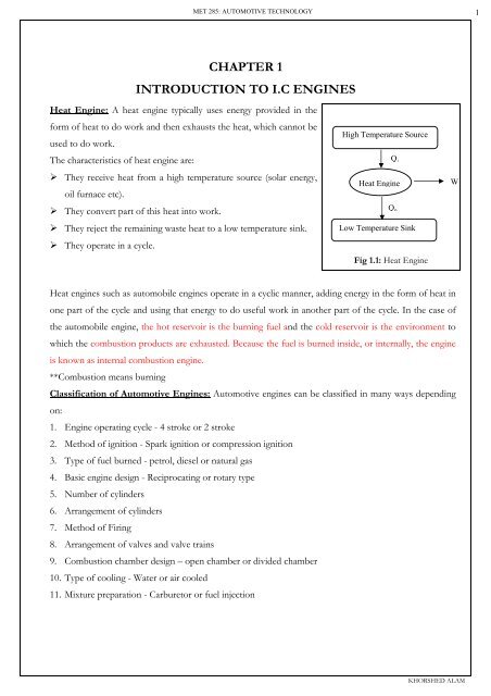
MET 285: AUTOMOTIVE TECHNOLOGY<br />
1<br />
CHAPTER 1<br />
INTRODUCTION TO I.C ENGINES<br />
Heat Engine: A heat engine typically uses energy provided in the<br />
form of heat to do work and then exhausts the heat, which cannot be<br />
used to do work.<br />
The characteristics of heat engine are:<br />
‣ They receive heat from a high temperature source (solar energy,<br />
oil furnace etc).<br />
‣ They convert part of this heat into work.<br />
‣ They reject the remaining waste heat to a low temperature sink.<br />
‣ They operate in a cycle.<br />
High Temperature Source<br />
Q i<br />
Heat Engine<br />
Q o<br />
Low Temperature Sink<br />
Fig 1.1: Heat Engine<br />
W<br />
Heat engines such as automobile engines operate in a cyclic manner, adding energy in the form of heat in<br />
one part of the cycle and using that energy to do useful work in another part of the cycle. In the case of<br />
the automobile engine, the hot reservoir is the burning fuel and the cold reservoir is the environment to<br />
which the combustion products are exhausted. Because the fuel is burned inside, or internally, the engine<br />
is known as internal combustion engine.<br />
**Combustion means burning<br />
Classification of Automotive Engines: Automotive engines can be classified in many ways depending<br />
on:<br />
1. Engine operating cycle - 4 stroke or 2 stroke<br />
2. Method of ignition - Spark ignition or compression ignition<br />
3. Type of fuel burned - petrol, diesel or natural gas<br />
4. Basic engine design - Reciprocating or rotary type<br />
5. Number of cylinders<br />
6. Arrangement of cylinders<br />
7. Method of Firing<br />
8. Arrangement of valves and valve trains<br />
9. Combustion chamber design – open chamber or divided chamber<br />
10. Type of cooling - Water or air cooled<br />
11. Mixture preparation - Carburetor or fuel injection<br />
KHORSHED ALAM
MET 285: AUTOMOTIVE TECHNOLOGY<br />
2<br />
1. Engine operating cycles:<br />
In reciprocating engines the piston moves up and down, this motion is transferred into a rotating motion<br />
in the drive shaft by the connecting rod and crank mechanism. The piston comes to rest at the top center<br />
crank position and the bottom center crank position respectively.<br />
One cycle is completed in 4-strokes for a conventional 4-stroke cycle engine and<br />
Two strokes in a 2-stroke cycle engine.<br />
Four stroke cycle: The majority of engines operate on 4-stroke cycle. Each cylinder requires 4 strokes of<br />
its piston i.e. two crankshaft revolution to produce one power stroke. Both S.I and C.I engines use this<br />
cycle. The 4-stroke cycle comprises of the following stages:<br />
Fig 1.2: 4-Stroke Cycle<br />
1. Intake stroke: Intake stroke starts with the piston at TC and ends with the piston at BC. During<br />
the stroke the intake valve opens to allow the fresh charge in. The pressure in the cylinder is less<br />
than the atmospheric pressure. As a result of the difference in pressures the charge flows into the<br />
cylinder. To increase the mass inducted, the inlet valve opens shortly before the stroke starts and<br />
closes after it ends.<br />
2. Compression stroke: The compression stroke starts when both the valves are closed and the<br />
mixture inside the cylinder is compressed to a small fraction of its initial volume. Towards the end<br />
of the compressions stroke, combustion is initiated and the cylinder pressure rises rapidly.<br />
3. Power stroke/Expansion stroke: It starts when the piston is at TC and ends at BC as the high<br />
temperature and pressure gases push the piston down and force the crank to rotate. As the piston<br />
approaches BC the exhaust valve opens to initiate the exhaust process and drop the cylinder<br />
KHORSHED ALAM
MET 285: AUTOMOTIVE TECHNOLOGY<br />
3<br />
pressure.<br />
4. Exhaust stroke: In this stroke the remaining burned gases exit the cylinder first and as the piston<br />
approaches TC the inlet valve opens and just after TC the exhaust valve closes and the cycle starts<br />
again.<br />
2- Stroke Engines: In 2- Stroke Engines ports are used to control the exhaust and inlet flows while the<br />
piston is close to BC. The 2- Stroke Engines comprises of the following stokes.<br />
1. Compression Stroke: It starts by closing the inlet and exhaust ports and then compresses the<br />
cylinder contents and draws fresh charge into the crankcase. As the piston approaches TC,<br />
combustion is initiated.<br />
2. Power Stroke: It is similar to 4- stroke until the piston approaches BC when first the exhaust<br />
ports and then intake ports are uncovered. Most of the burnt gases exit the cylinder in an exhaust<br />
blow down process. When the inlet ports are uncovered the fresh charge, which has been,<br />
compressed in the crankcase flows into the cylinder.<br />
Fig 1.3:<br />
KHORSHED ALAM
MET 285: AUTOMOTIVE TECHNOLOGY<br />
4<br />
The two-stroke engine produces twice the power as the four-stroke engine. However this does not make<br />
the two strokes twice as powerful. When the piston opens the transfer and exhaust ports there is always<br />
some mixing of fresh air-fuel mixture with the exhaust gases. This reduces the amount of fresh air-fuel<br />
mixture that enters. Also, only part of the piston stroke helps get air-fuel mixture into the cylinder. This<br />
further reduces the amount of air-fuel mixture that enters. And only part of the down stroke of the piston<br />
produces power.<br />
Comparison of 2-Stroke and 4-Stroke engines:<br />
1. For the same speed the power of the two-stroke is twice that of four-stroke.<br />
2. For the same power two-stroke is lighter than four strokes and occupies less space.<br />
3. The two stoke engines require lighter flywheel and foundation in comparison to four-stroke<br />
engines.<br />
4. There are no valves in 2-stroke engines only ports are present. Hence mechanism is simple.<br />
5. Scavenging is very poor in 2-stroke engine.<br />
6. In 2- stroke engines inlet and outlet valve open simultaneously resulting in low thermal efficiency.<br />
2. Method of ignition:<br />
Depending upon the method of ignition the I.C engines are classified as spark ignition (S.I) and<br />
compression ignition ( C.I ) engines.<br />
In (SI) spark ignition the fuel and air mixture is prepared outside the cylinder in a carburetor. From the<br />
carburetor the accurately metered quantity of the fuel mixture is fed into the cylinders where it is ignited<br />
by an electric spark.<br />
In C.I engines the fuel air mixture is prepared in the cylinder. The cylinder is charged with the air and<br />
then it is compressed. Thus the air being heated to a very high temperature at the end of the compression<br />
gets a finely atomized injected under a high pressure. This fine spray of fuel coming into contact with<br />
very hot air gets ignited and it is called compression ignition.<br />
3. Type of fuel burned: Spark ignition engines usually burn gasoline (petrol) whereas compression<br />
ignition engines uses diesel as fuel. The S.I engine works on Otto cycle and C.I engines works on Diesel<br />
engine cycle.<br />
KHORSHED ALAM
MET 285: AUTOMOTIVE TECHNOLOGY<br />
5<br />
Otto Cycle:<br />
‣ It is an ideal cycle that approximates a spark ignition internal combustion engine.<br />
‣ It consists of two reversible adiabatic (without loss of heat) and two constant volume processes.<br />
Reversible adiabatic<br />
4<br />
4<br />
V=C S =C<br />
V=C<br />
5<br />
P 3<br />
V=C<br />
1 2<br />
T<br />
S =C<br />
3<br />
2<br />
V=C<br />
5<br />
V<br />
s<br />
T.C<br />
B.C<br />
1-2 Intake/suction: Air/Fuel mixture is drawn into<br />
the cylinder.<br />
2-3 Compression: The mixture is compressed<br />
adiabatically.<br />
3-4 Combustion: The mixture is ignited and<br />
burned at constant volume.<br />
4-5 Expansion: The gases then expand adiabatically<br />
5-2 Heat is discharged at constant volume<br />
2-1 Gases are swept out of the cylinder at constant<br />
pressure.<br />
Fig 1.4: Otto cycle<br />
Ratio of compression/Ratio of expansion (r):<br />
V<br />
2 =<br />
Heat supplied during the process 3-4: Q i = mC v (T 4 -T 3 )<br />
Heat rejected during 5-2: Q o = mC v (T 5 -T 2 )<br />
Thermal efficiency for Otto cycle: η =<br />
W<br />
Q<br />
i<br />
V<br />
3<br />
i<br />
V<br />
V<br />
Q − Q<br />
5<br />
4<br />
i o<br />
= =<br />
Q<br />
T<br />
1−<br />
T<br />
2<br />
3<br />
T<br />
(<br />
T<br />
T<br />
(<br />
T<br />
5<br />
2<br />
4<br />
3<br />
−1)<br />
−1)<br />
KHORSHED ALAM
MET 285: AUTOMOTIVE TECHNOLOGY<br />
6<br />
We know further,<br />
T<br />
T<br />
3<br />
2<br />
V<br />
= (<br />
V<br />
2<br />
3<br />
)<br />
k −1<br />
V<br />
= (<br />
V<br />
5 k−1<br />
)<br />
4<br />
T<br />
=<br />
T<br />
T4<br />
Therefore, =<br />
T<br />
3<br />
4<br />
5<br />
T<br />
=<br />
T<br />
5<br />
2<br />
70<br />
η<br />
T2<br />
k<br />
and η = 1−<br />
= 1 − r 1−<br />
= 1 1<br />
−<br />
T r k − 1<br />
3<br />
r<br />
15<br />
Fig 1.5: Thermal efficiency of Otto cycle as a<br />
function of compression ratio.<br />
Diesel Cycle:<br />
‣ In diesel engine cycle only air without fuel is compressed and at the end of the compression stroke,<br />
fuel is injected into the compressed air and burns immediately.<br />
‣ It consists of two reversible adiabatic, one constant volume and one constant pressure processes.<br />
Reversible adiabatic 4<br />
3<br />
4<br />
P=C<br />
S =C<br />
P<br />
5<br />
T<br />
S=C<br />
3<br />
5<br />
V=C<br />
1 2<br />
2<br />
V<br />
s<br />
Ratio of compression (r):<br />
1-2 Intake/suction: Air/Fuel mixture is drawn into the cylinder.<br />
2-3 Compression: The mixture is compressed adiabatically.<br />
3-4 Combustion: The mixture is ignited and burned at constant pressure.<br />
4-5 Expansion: The gases then expand adiabatically<br />
5-2 Heat is discharged at constant volume<br />
2-1 Gases are swept out of the cylinder at constant pressure.<br />
Fig 1.6: Diesel cycle<br />
V2<br />
and Cutoff ratio (rc ):<br />
V<br />
3<br />
Heat supplied during the process 3-4: Q i = mC p (T 4 -T 3 ) & Heat rejected during 5-2: Q o = mC v (T 5 -T 2 )<br />
V<br />
V<br />
4<br />
3<br />
KHORSHED ALAM
MET 285: AUTOMOTIVE TECHNOLOGY<br />
7<br />
1<br />
Thermal efficiency for diesel cycle: η =1-<br />
k<br />
kr<br />
−1<br />
rc<br />
(<br />
r<br />
c<br />
k<br />
−1<br />
)<br />
−1<br />
Comparison of Otto and diesel cycle:<br />
Case 1: Same state at the beginning of compression and same piston displacement and compression ratio.<br />
4<br />
4<br />
P<br />
3<br />
4'<br />
5<br />
T<br />
3<br />
V=C<br />
P=C<br />
4'<br />
5<br />
1 2<br />
2<br />
V<br />
s<br />
Otto cycle: 1-2-3-4-5-2-1 ; Diesel cycle: 1-2-3-4'-5-2-1<br />
Efficiency of Otto Cycle is higher than diesel cycle<br />
Case 2: Compression ratio of diesel cycle is much higher than Otto cycle<br />
4<br />
p=C<br />
P<br />
3' 4<br />
3<br />
5 3<br />
T<br />
3’<br />
v=C<br />
5<br />
1 1' 2 2<br />
s<br />
V<br />
Otto cycle: 1-2-3-4-5-2-1 ; Diesel cycle: 1'-2-3'-4-5-2-1'<br />
Efficiency of Otto Cycle is lower than diesel cycle<br />
Differences between Petrol and Diesel Engines:<br />
Petrol Engine<br />
It costs less, but running cost is more due to<br />
1<br />
costly fuel.<br />
Air and petrol mixture is sucked through inlet<br />
2<br />
valve.<br />
Diesel Engine<br />
It costs more initially, but the running cost is<br />
less as the diesel is cheaper than petrol.<br />
Only air is sucked during suction stroke.<br />
KHORSHED ALAM
MET 285: AUTOMOTIVE TECHNOLOGY<br />
8<br />
3 Spark plug is used to ignite the mixture. An injector injects the fuel at high pressure<br />
4 It works on Otto cycle. It works on Diesel cycle.<br />
5 Carburetor is used to prepare the mixture. Fuel pump and injector is used.<br />
6 Compression ratio is from 6:1 to 9:1 Compression ratio is from 12:1 to 22:1<br />
7 Lighter in weight. Heavier in weight.<br />
8 Starting is easy due to low compression ratio.<br />
Starting is difficult due to high compression<br />
ratio.<br />
9 Maintenance cost is higher. Maintenance cost is lower.<br />
10<br />
No vibration when the engine is running idle or<br />
slow.<br />
Due to diesel knock the vibrations are always<br />
there.<br />
Geometrical Properties of Engine:<br />
a. Top Center (TC): The position at which the cylinder<br />
volume is minimum.<br />
b. Bottom Center (BC): The position at which the cylinder<br />
volume is maximum.<br />
c. Cylinder Bore (B): Inside diameter of the cylinder.<br />
d. Piston Stroke (L): The distance between the Top center<br />
and bottom center.<br />
e. Connecting Rod Length (l): It is the length of<br />
connecting rod.<br />
f. Crank Radius (a): It is the radius of the crank. (Stroke<br />
and crank radius are related by L = 2a)<br />
g. Clearance Volume (V c ): The volume of the combustion<br />
chamber when the piston is at the Top center (TC).<br />
h. Displacement Volume (V d ): The volume swept out by<br />
the piston or displaced volume is defined as the difference<br />
between the total volume (V t ) and the clearance volume<br />
(Vc)(V d = Vt - V c)<br />
Maximum cylinder volume<br />
i. Compression Ratio (r c ): r c = =<br />
Minimum cylinder volume<br />
Vc + Vd<br />
Vc<br />
Fig.1.7: Geometrical details<br />
KHORSHED ALAM
MET 285: AUTOMOTIVE TECHNOLOGY<br />
9<br />
Engine Parameters<br />
(a) Mean Piston Speed (Sp)<br />
(b) Brake Torque (T):<br />
It is a measure of an engine ability to do work.<br />
(c) Brake Power (P b ):<br />
It is the rate at which work is done.<br />
(d) Indicated Power (P i ): The rate of work transfer<br />
from the gas within the cylinder to the piston.<br />
(e) Friction Power (P f ): It is the power required to<br />
overcome friction of the bearings, piston and other<br />
mechanical components of the engine and to drive<br />
the engine accessories.<br />
(f) Mechanical Efficiency (η m ): The ratio of the<br />
brake power delivered by the engine to the<br />
indicated power is called the mechanical efficiency<br />
(g) Mean Effective Pressure (mep): It is the ratio of<br />
work per cycle to the displaced cylinder volume per<br />
cycle.<br />
Sp = 2LN<br />
T = F x b, where F is the force and b is the<br />
perpendicular distance.<br />
P =<br />
i<br />
WN<br />
nR<br />
P = 2πNT<br />
b<br />
; Where nR is the number of<br />
crankshaft revolutions for each power<br />
stroke per cylinder.<br />
**Four stroke n R = 2; Two stroke n R = 1<br />
Relation between indicated power, brake<br />
power and friction power<br />
P i = Pb +P f:<br />
Pb<br />
η m =<br />
P<br />
3<br />
P(<br />
kW ). nR.10<br />
mep( kPa)<br />
=<br />
3<br />
Vd<br />
( dm ). N(<br />
rev / s)<br />
6.28. nR.<br />
T ( N.<br />
m)<br />
=<br />
3<br />
V ( dm )<br />
(h) Specific Fuel Consumption: The fuel flow rate<br />
m<br />
f<br />
( g / h)<br />
sfc(<br />
g / kW.<br />
h)<br />
= ;<br />
per unit power output. P(<br />
kW )<br />
d<br />
i<br />
(i) Fuel Conversion Efficiency: It is measure of<br />
engine efficiency.<br />
(j) Volumetric Efficiency: It is defined as the volume<br />
flow rate of air into the intake system divided by<br />
the rate at which volume is displaced by the piston.<br />
1<br />
η =<br />
sfc(<br />
mg / J ). Q<br />
m<br />
f<br />
( g / s)<br />
sfc(<br />
mg / J ) =<br />
P(<br />
kW )<br />
f<br />
HV<br />
( MJ / kg)<br />
=<br />
ma<br />
η<br />
v<br />
=<br />
ρ V<br />
a,<br />
i<br />
3600<br />
sfc(<br />
g / kW.<br />
h).<br />
Q<br />
d<br />
HV<br />
( MJ / kg)<br />
KHORSHED ALAM
MET 285: AUTOMOTIVE TECHNOLOGY<br />
10<br />
TUTORIAL 1<br />
1. The compression ratio in an Otto cycle is 8. At the beginning of the compression<br />
stroke the pressure is 0.1 Mpa and the temperature is 15 0 C. The heat transfer to<br />
the mixture is 1800 kJ/kg. Determine<br />
(a) The pressure and temperature at the end of each process of the cycle.<br />
(b) The thermal efficiency<br />
(c) The mean effective pressure<br />
2. A four cylinder automotive S.I engine is being designed to provide maximum brake<br />
torque of 150 N.m. The maximum brake mean effective pressure is 925 Kpa.<br />
Estimate the required engine displacement, bore and stroke and the maximum<br />
brake power the engine will deliver. The maximum rated engine speed is 87 rev/s<br />
and assume B = L.<br />
3. Calculate the mean piston speed, bmep and specific power of direct injection four<br />
stroke six cylinder Cummins diesel engine<br />
Displaced volume = 10 l, bore = 125 mm, stroke = 136 mm, compression ratio =<br />
16.3, maximum power = 168 Kw at rated speed of 2100 rev/min.<br />
4. The diesel engine of problem (3) is operating at a mean piston speed of 8 m/s.<br />
Calculated the air flow if the volumetric efficiency is 0.92. If (F/A) is 0.05 what is<br />
the fuel flow rate?<br />
5. The compression of a diesel cycle is 18. At the beginning of the compression<br />
stroke the pressure is 0.1 Mpa and the temperature is 15 0 C. The heat transfer to<br />
the air is 1800 kJ/kg. Determine<br />
(a) The pressure and temperature at the end of each process of the cycle.<br />
(b) The thermal efficiency<br />
(c) The mean effective pressure<br />
6. An engine has a swept volume of 300 cm 3 . If the compression ration is 8.5:1,<br />
determine the clearance volume.<br />
KHORSHED ALAM
MET285: AUTOMOTIVE TECHNOLOGY<br />
11<br />
CHAPTER 2<br />
CONSTRUCTIONAL DETAILS OF ENGINE (I)<br />
Engine Types: Number and arrangement of cylinders<br />
Cylinders can be arranged<br />
1. In a row (inline)<br />
2. In two rows or banks set at an angle (V type)<br />
3. In two rows or banks opposing each other (flat, pancake, or opposedcylinder<br />
type)<br />
4. Likes spokes on a wheel<br />
Important Points:<br />
‣ In-line engines have their cylinders arranged in a row. 3, 4, 5 and 6<br />
cylinder engines commonly use this arrangement.<br />
‣ The "V" arrangement uses two banks of cylinders side-by-side and is<br />
commonly used in V-6, V-8, V-10 and V-12 configurations.<br />
‣ Flat engines use two opposing banks of cylinders and are less common<br />
than the other two designs. They are used in Subaru's and Porsches in 4<br />
and 6 cylinder arrangements as well as in the old VW beetles with 4<br />
cylinders. Flat engines are also used in some Ferrari's with 12 cylinders.<br />
Fig 2.1: Cylinder<br />
arrangements<br />
Basic components of an engine<br />
1. Cylinder head: A cylinder head is bolted to the top of each bank of cylinders to seal the individual<br />
cylinders and contain the combustion process that takes place inside the cylinder. The cylinder head<br />
contains at least one intake valve and one exhaust valve for each cylinder.<br />
Most engines have two<br />
Fig 2.2: Cylinder Head<br />
valves per cylinder, one<br />
intake valve and one<br />
exhaust valve. Some newer<br />
engines are using multiple<br />
intakes and exhaust valves<br />
per cylinder for increased<br />
engine power and<br />
efficiency.<br />
These engines are sometimes named for the number of valves that they have such as "24 Valve V6" which<br />
K. Alam
MET285: AUTOMOTIVE TECHNOLOGY<br />
12<br />
indicates a V-6 engine with four valves per cylinder. Modern engine designs can use anywhere from 2 to 5<br />
valves per cylinder.<br />
2. Cylinder block and crankcase: The engine block or<br />
cylinder block is the foundation of the engine. All other<br />
engine parts are assembled in or someway attached to the<br />
cylinder block. The large holes in the block are the cylinder<br />
bores. Water cooled engines have passages surrounding each<br />
cylinder, valve and spark plug. Coolant flows through these<br />
spaces to pick up heat and carry it away from the engine.<br />
Parts attached to and installed in block:<br />
a) Crankshaft with main bearings<br />
b) Piston and piston rings<br />
c) Connecting rod<br />
d) Cylinder head<br />
e) Oil sump and pump<br />
3. Engine Manifold: For the engine to run, it must able to<br />
“breathe”. Passages must carry the air or air-fuel mixture to<br />
the intake ports in the cylinder head. Then, after combustion,<br />
other passages must carry the burned gases away from the<br />
exhaust ports in the cylinder head.<br />
Fig 2.3: Cylinder Block<br />
Fig 2.4: Engine Manifold<br />
4. Oil sump: The sump is steel pressing bolted to the underside of the crankcase and used to hold the oil.<br />
K. Alam
MET285: AUTOMOTIVE TECHNOLOGY<br />
13<br />
5. Cylinders: The cylinders form the stationary part of the gas tight seal in which the piston moves.<br />
6. Pistons: The piston forms a sliding gas<br />
tight seal in the cylinder bore and transmits<br />
the force of the gas pressure to the small<br />
end of the connecting rod. The piston must<br />
posses the following characteristics.<br />
a. Rigidity to withstand the high pressure.<br />
b. Light<br />
c. Good heat conductivity<br />
Fig 2.5: Piston<br />
d. Low expansion coefficients<br />
** Pistons are made of aluminum because it is a<br />
light metal. It can either be cast or forged.<br />
7. Piston rings: To prevent the escape of<br />
expanding gases piston rings are fitted into<br />
the grooves of the piston. The piston rings<br />
also prevent oil from entering into the<br />
combustion chamber and also conduct heat<br />
from the piston to the cylinder walls.<br />
Usually pistons are fitted with two<br />
compression rings and one oil ring.<br />
a. Compression rings seal compression and<br />
combustion pressure in the combustion<br />
chambers and help prevent blowby.<br />
b. Oil rings scrapes the excess oil off the<br />
cylinder walls and returns the oil to the<br />
Fig 2.6: Piston Rings<br />
crankcase.<br />
8. Gudgeon pin: The gudgeon pin connects the piston to the connecting rod.<br />
Fig 2.7: Gudgeon Pin<br />
K. Alam
MET285: AUTOMOTIVE TECHNOLOGY<br />
14<br />
9. Connecting rod: The purpose of the connecting<br />
rod is to connect the piston and the crankshaft at<br />
the same time converting up and down motion or<br />
reciprocating motion of the piston to rotary<br />
motion at the crankshaft. The small end of the<br />
connecting rod is connected to the piston while<br />
the big end is fixed to the crankshaft.<br />
10. Crankshaft: The crankshaft is a one piece casting<br />
or forging of heat treated alloy steel. Counter<br />
weights placed opposite the connecting rod<br />
journals balance the crankshaft. A journal is any<br />
part of a shaft that rotates in a bearing. The<br />
output end of the crankshaft has the flywheel or<br />
drive plate attached to it. The front end has the<br />
gear or sprocket that drives the camshaft, the<br />
vibration damper and the drive-belt pulley.<br />
Fig 2.8: Connecting Rod<br />
Fig 2.9: Crankshaft<br />
K. Alam
MET285: AUTOMOTIVE TECHNOLOGY<br />
15<br />
11. Flywheel: Each power stroke delivers a sudden power impulse to the crankshaft. This causes the<br />
crankshaft to speed up.<br />
During the other three piston<br />
strokes, the crankshaft tries to slow<br />
down. However, a weight on one<br />
end of the crankshaft helps it<br />
turning smoothly. On vehicles with<br />
a manual transmission this weight is<br />
a heavy metal flywheel that bolts to<br />
Fig 2.10: Flywheel<br />
the rear end of the crankshaft.<br />
The flywheel helps smooth out the power flow by resisting any sudden change in the crankshaft’s<br />
speed of rotation. Vehicles with an automatic transmission have a light drive plate with a fluid filled<br />
torque converter attached to the crankshaft. Some engines have a dual or tandem mass flywheel.<br />
This is basically two separate flywheels, a primary flywheel and a secondary flywheel. The primary<br />
flywheel attaches to the crankshaft flange. As the crankshaft rotates, engine power is transmitted<br />
from the primary flywheel through torsional springs to the secondary flywheel. This arrangement<br />
allows the springs to absorb the crankshaft torsional vibration caused by the engine power impulses.<br />
Fig 2.11: Primary & Secondary Flywheel<br />
K. Alam
MET285: AUTOMOTIVE TECHNOLOGY<br />
16<br />
12. Valves: Valves allow the engine to “breathe”. Intake valves open to admit air-fuel mixture toe the<br />
cylinders. Exhaust valves open to allow burned gases to exit or exhaust from the cylinders. Valves open<br />
and close at predetermined times, which vary with different engines. They are several different<br />
arrangements of valves and valve trains. They differ in<br />
a) Location of the camshaft<br />
b) How the camshaft is driven<br />
c) Type of valve train<br />
d) Number of valves per cylinder<br />
a) Location of the camshaft: The camshaft is either in the cylinder block or on the cylinder head. An<br />
engine with the camshaft in the block is an overhead valve (OHV) or pushrod engine. When the<br />
camshaft is on or in the cylinder head, the engine is an overhead camshaft (OHC) engine.<br />
b) Type of camshaft drive: Camshafts are driven by timing gears, sprockets and timing chain or sprockets<br />
and toothed timing belt. Some engines use a combination of timing chain and timing belt to drive the<br />
camshafts.<br />
K. Alam
MET285: AUTOMOTIVE TECHNOLOGY<br />
17<br />
c) Type of valve train: Three types of valve trains are shown in figure below<br />
K. Alam
MET285: AUTOMOTIVE TECHNOLOGY<br />
18<br />
d) Number of valves per cylinder: Some engines have more then two valves per cylinder. Some have<br />
three, four, five and even six valves in each cylinder. These are multivalve engines.<br />
13. Camshaft: The function of the camshaft is to operate the valves. The camshaft can either be located<br />
overhead or at the side of the engine.<br />
camp lobe with necessary figure.<br />
explain the<br />
Combustion Chamber shapes:<br />
The combustion chamber usually cast into the cylinder head and then machined as necessary. The greater the<br />
turbulence of the A/F mixture in combustion chamber the faster it burns. There are four basic shapes of the<br />
combustion chamber.<br />
1. Wedge: It increases the turbulence (Unrest) of<br />
the burning mixture but has high exhaust<br />
emissions.<br />
2. Hemispheric (open): It provides relatively slow<br />
burning.<br />
3. Cup (bowl): A flat cylinder head is used with a<br />
piston that has a cup or bowl in its tops. This<br />
forms a combustion chamber that improves<br />
turbulence in diesel, turbo charged and high<br />
performance engine.<br />
4. Crescent (pent roof): The crescent or pent roof<br />
can be easily be changed to vary the compression<br />
ratio and turbulence. Only the height and shape<br />
of the piston head must be changed.<br />
K. Alam
MET285: AUTOMOTIVE TECHNOLOGY<br />
19<br />
Pre-combustion chamber: A pre-combustion chamber is a separate small combustion chamber where<br />
combustion begins. A primary intake valve opens into the main combustion chamber. An auxiliary<br />
intake valve opens into the pre-combustion chamber. Both the valves open at the same time. The<br />
auxiliary intake valve admits the rich mixture. The primary intake valve admits the lean mixture. The<br />
spark plug in the pre-combustion chamber ignites the rich mixture.<br />
The burning rich mixture then streams out of the pre-combustion chamber rapidly mixing with and<br />
igniting the lean mixture in the main combustion chamber. The effect produces high turbulence and<br />
good combustion. A spark-ignition engine using a pre-combustion chamber is a stratified-charged<br />
engine. (“Stratified” means in layers).<br />
** The diesel engine is a stratified charge engine<br />
K. Alam
MET285: AUTOMOTIVE TECHNOLOGY<br />
20<br />
Knocking in S.I Engines<br />
Scavenging: It is a process of removing the burnt gases in internal combustion engines from the<br />
combustion chamber of the engine cylinder.<br />
Supercharging: Supercharging is supplying the intake air to the engine cylinder at a pressure greater than<br />
the pressure of surrounding atmosphere using blower or compressor.<br />
Advantages: When pressure increases, density and temperature also increases resulting in better combustion.<br />
Disadvantage: It increases the possibility of detonation (explosion) in petrol engines and decreases the<br />
knocking in diesel.<br />
Auto-ignition: Phenomena by which a fuel catches fire without external flame.<br />
Pre-ignition: It is ignition of the charge in S.I engine before the spark occurs in the spark plug.<br />
Ignition Lag: Time taken by the fuel after injection to reach up to auto-ignition temperature.<br />
Detonation: The rapid auto-ignition of a portion of a fuel causes pressure waves. These waves are of high<br />
intensity resulting in blow to cylinder making loud noise resulting in knocking of the engine.<br />
Knocking can be classified as<br />
‣ Knocking in SI Engine – sudden auto ignition farthest away from the spark plug.<br />
‣ Knocking in CI engine – sudden auto ignition of the mixture at the very beginning of the<br />
combustion process.<br />
Knocking in S.I engine: It can be prevented if the end mixture is having<br />
‣ Low density: Knocking increases by supercharging the engine, opening throttle, increasing the<br />
compression ratio and advancing the spark timing.<br />
‣ Low temperature: Knocking increases by supercharging, increasing the inlet air temperature,<br />
increasing the coolant air temperature and compression ratio.<br />
‣ Long ignition delay: knocking increases by decreasing the speed and turbulence and increasing the<br />
distance of the flame travel in combustion process.<br />
‣ Lean or rich mixture: Possibility of knocking increased by low self-ignition temperature, chemically<br />
correct mixture and short ignition delay. (Rich mixture is sometimes used to suppress knocking)<br />
Knocking in C.I engine: It can be prevented if the first element of the fuel and air is having high density,<br />
high temperature, short ignition delay and reactive mixture.<br />
Octane number: The percentage volume of iso-octane in a mixture of iso-octane and normal heptane (nheptane),<br />
which shows the tendency to knock as the given fuel when tested in a specified condition is<br />
known as octane number of the fuel.<br />
Cetane number: The percentage volume of cetane in a mixture of cetane and alpha methyl naphthalene,<br />
which gives the same ignition delay as the given fuel when tested in a specified condition is known as cetane<br />
number.<br />
K. Alam
MET285: AUTOMOTIVE TECHNOLOGY<br />
21<br />
Exercise<br />
1. Identify the type of engines<br />
K. Alam
MET 285: AUTOMOTIVE TECHNOLOGY<br />
22<br />
CHAPTER 3<br />
LUBRICATION<br />
Engine bearing surfaces: The engine bearing surfaces in an internal combustion engines are<br />
1. Cylinder surfaces 2. Connecting rod bearing 3. Crankshaft bearing 4. Valve mechanism bearings<br />
Purpose of lubricating oil<br />
a. The oil lubricates moving parts to reduce wear<br />
b. As the oil moves through the engine, the oil picks up heat.<br />
c. Oil fills the clearance between bearings and rotating journals<br />
d. The oil helps form a gas tight seal between piston rings and cylinder walls.<br />
e. The oil acts as a cleaning agent.<br />
Note:<br />
1. The oil on the cylinder surfaces should provide a seal against leakage.<br />
2. It prevents the piston from touching the cylinder surface<br />
3. The lubricant must have high flash point which is higher than the inside surface temperature of the<br />
cylinder at this point.<br />
4. Higher the operating temperature the higher should be the viscous characteristics of the lubricant.<br />
5. For large piston clearances, oil with a heavy body should be used.<br />
6. Light oils should be used for connecting rod bearings and crankshaft operating at high rubbing speed<br />
and low loads.<br />
7. The power required for starting an engine at low temperature depends principally upon the viscosity of<br />
the oil in the bearing surface at that temperature.<br />
Classification of lubrication system<br />
Lubrication systems may be classified as follows - Splash and Pressure feed<br />
Splash system: The lower ends of the connecting rods, dip into the oil and splash it over the lower cylinder<br />
surfaces as well as the crank-case surfaces. The piston spreads the oil over the cylinder surfaces while the ducts<br />
or channels lead the oil from other surfaces to the crankshaft and cam-shaft bearings. The lower connecting<br />
rod bearings have oil forced in through a hole in the lower half during the time the rod dips into the oil.<br />
Disadvantage: Lack of positive circulation to the bearings which limits the bearing loading and quantity of oil<br />
circulated.<br />
Pressure Feed: The force-feed system supplies oil under pressure to the various bearings. The oil flows<br />
through a strainer and into the suction line of the pump, all of which is usually located in a sump in the bottom<br />
of the crankcase.<br />
KHORSHED ALAM
MET 285: AUTOMOTIVE TECHNOLOGY<br />
23<br />
Figure 1 shows the lubricating system for an inline 4<br />
cylinder overhead camshaft engine. The oil pump<br />
picks up oil from the oil pan. The pump sends the oil<br />
through the oil lines to the main bearing that support<br />
the crankshaft. Some oil flows from the main bearing<br />
through oil holes drilled in the crankshaft to the rod<br />
bearings. The oil flows through the bearing oil<br />
clearance and then is thrown off the moving parts. At<br />
the same time, oil flows through an oil line to the<br />
cylinder head. There the oil flows through an oil<br />
gallery to lubricate the camshaft bearings and valve<br />
train parts. After the oil circulates to all engine parts, it<br />
drops back down into the oil pan.<br />
Fig 1: Lubricating System for a four cylinder OHV S.I Engine<br />
Figure 2 shows the lubricating<br />
system for an inline overhead valve<br />
(OHV) engine. Oil flows up through<br />
hollow pushrods to lubricate the<br />
rocker arms and valve stems. Some<br />
of the oil thrown off the connecting<br />
rod bearing lands on the cylinder<br />
walls. This lubricates the pistons,<br />
piston rings and piston pins.<br />
Fig 2: Lubricating system for an inline OHV engine<br />
KHORSHED ALAM
MET 285: AUTOMOTIVE TECHNOLOGY<br />
24<br />
Lubricating System Components:<br />
1. Oil Pan:<br />
It is fitted on the bottom of the cylinder block to store the oil.<br />
A gasket between the pan and the block seal the joint and prevent oil leaks.<br />
Most pans hold 3L to 8L of oil<br />
2. Oil Pump:<br />
Two types of oil pumps used in automotive engines: gear and rotor.<br />
In overhead valve engines the camshaft spiral gear that drives the ignition distributor usually drives the oil<br />
pump.<br />
Some engines drive the distributor directly from the end of an overhead camshaft. The oil pump on these<br />
engines may be driven by a separate drive shaft or jackshaft.<br />
3. Pressure Relief Valve<br />
To prevent excessive oil pressure, the lubricating system has a pressure regulator valve or relief valve.<br />
It is a spring loaded ball or plunger<br />
4. Oil cooler<br />
It prevents oil from getting too hot.<br />
In the oil cooler, engine coolant flows past tubes carrying hot oil. The coolant picks up the heat and carries it<br />
to the radiator.<br />
5. Oil filters<br />
The filter allows the oil to pass through while trapping particles of dirt and carbon.<br />
The filter has a pleated paper filtering element.<br />
The filter has a spring loaded bypass valve to protect the engine from starvation if the filter clogs.<br />
6. Lubricating system Indicators<br />
Indicator Light<br />
Electric, electronic or digital gauge for oil pressure<br />
Dip stick<br />
Oil change indicator<br />
Types of filtration systems: The pump distributes the oil to the crankshaft bearings, piston and camshaft.<br />
The pressure feed lubrication system is of two types<br />
1. Full flow filtration system – The oil is filtered before it is send to the bearings.<br />
2. By pass filtration system - The oil is filtered after it lubricates the bearings.<br />
KHORSHED ALAM
MET 285: AUTOMOTIVE TECHNOLOGY<br />
25<br />
Full flow filtration system<br />
By pass filtration system<br />
Properties of lubricating oil<br />
1. Proper viscosity: Engine oil should have the proper viscosity so it flows easily to all moving engine parts.<br />
Low viscosity reduces the ability of the oil to stay in place between moving parts.<br />
If the oil is too thin it is forced out from between the moving parts. Rapid wear results.<br />
KHORSHED ALAM
MET 285: AUTOMOTIVE TECHNOLOGY<br />
26<br />
An oil that is too thick flows too slowly to engine parts, especially when the engine and oil are cold. This also<br />
caused rapid engine wear.<br />
2. Viscosity Index: This is a measure of how much the viscosity of an oil changes with temperature.<br />
Viscosity index improvers are added to engine oil so its viscosity stays more nearly the same, hot or cold.<br />
3. Viscosity numbers: Oils are rated for winter or for other than winter.<br />
Winter grade oils are SAE 5W, SAE 10 W … (SAE stands for society of automotive engineers).<br />
The W stands for winter. For other than winter use, single viscosity oil grades are SAE 20, SAE 30 …..<br />
The higher the number, the thicker the oil<br />
4. Multiple viscosity oil: A multiple viscosity oil graded SAE 5W-30 has the viscosity of an SAE5W oil<br />
when cold and SAE30 when hot.<br />
5. Resistance to carbon formation and oil oxidation<br />
6. Corrosion and rust inhibitors<br />
7. Foaming resistance<br />
8. Detergents-dispersants<br />
9. Extreme pressure resistance<br />
10. Energy conserving oils<br />
11. Synthetic oil<br />
2 Stroke Gasoline/Petrol Lubrication<br />
‣ Most 2-stroke gasoline/petrol engines use a set gasoline/petrol-oil mixture for lubrication. As the air, fuel<br />
and oil enter the crankcase, the fuel evaporates, leaving behind enough oil to keep parts coated and<br />
lubricated.<br />
‣ Oil Injection system: An oil injection system doesn’t need the oil and gasoline/petrol mixed manually.<br />
An engine-driven oil pump takes oil from a tank and pumps a measured amount directly into the engine<br />
where it mixes with the fuel and lubricates the internal engine parts.<br />
KHORSHED ALAM
MET285: AUTOMOTIVE TECHNOLOGY<br />
CHAPTER 4: CARBURETOR<br />
A Carburetor is a mixing device that can supply a<br />
spark ignition engine with a combustible mixture of<br />
air and fuel.<br />
Types of carburetor:<br />
• Fixed venturi/Variable venturi<br />
• Single barrel/two barrel/4 barrel<br />
• Feed back/ Non-feed back<br />
Float-type Carburetor<br />
• A fuel metering device that uses a float-actuated<br />
needle valve to maintain fuel level slightly<br />
below the edge of the discharge nozzle.<br />
• Measures the amount of air entering the engine.<br />
• Meter into this air the correct amount of<br />
atomized liquid gasoline.<br />
• Convert the liquid fuel into fuel vapors and<br />
distributes uniformly to the cylinders.<br />
• Varies mixture based on engine needs.<br />
• Internal Systems<br />
• Float system<br />
• Idling system<br />
• Metering System<br />
• Power System<br />
• Acceleration system<br />
• Choke system<br />
KHORSHED ALAM<br />
1
MET285: AUTOMOTIVE TECHNOLOGY<br />
A/F ratio with different speeds<br />
Choke system supplies a rich mixture for<br />
starting.<br />
As the engine warms up and its speed increases,<br />
the mixture leans out.<br />
At intermediate speed, with the throttle valve<br />
only partly open, both idle and main metering<br />
system supply fuel.<br />
As the throttle opens wider, the main metering<br />
system takes over completely.<br />
At full throttle and higher speeds, the power<br />
system comes on. It enriches the air-fuel<br />
mixture for full power.<br />
IDLE SYSTEM<br />
When the throttle is closed there is not enough<br />
air flowing to produce a pressure low enough to<br />
pull the fuel from the float bowl through the<br />
main metering jet, so a separate system is used.<br />
When the engine is idling all air must pass<br />
around the edge of a butterfly valve.<br />
– Airflow is restricted, causing travel<br />
at high velocities resulting in lower<br />
pressures.<br />
The idle mixture adjustment knob controls the<br />
amount of fuel flow and allows a smooth idle<br />
to be set at any given speed.<br />
KHORSHED ALAM<br />
2
MET285: AUTOMOTIVE TECHNOLOGY<br />
LOW SPEED OPERATION<br />
When the throttle valve opens slightly and the<br />
edge of the throttle valve moves above the idle<br />
port to the low speed port or transfer port.<br />
MAIN METERING SYSTEM<br />
The throttle valve is open and the main nozzle<br />
is discharging fuel.<br />
The wider the throttle opens, the faster the air<br />
flows through and the greater the venture<br />
vacuum. This causes more fuel to discharge<br />
from the main nozzle to maintain the proper<br />
air-fuel ratio.<br />
POWER SYSTEM<br />
For high speed, full power, wide open<br />
throttle operation, the air-fuel mixture must<br />
be enriched.<br />
When the throttle valve is open, the metering<br />
rod is raised so that the smaller diameter of<br />
the rod is in the jet. This allows additional<br />
fuel to flow.<br />
KHORSHED ALAM<br />
3
MET285: AUTOMOTIVE TECHNOLOGY<br />
ACCELERATION PUMP SYSTEM<br />
When the throttle valve opens for vehicle<br />
acceleration, there is a sudden rush of air<br />
through the carburetor. Unless additional fuel is<br />
immediately delivered, the air fuel mixture will<br />
be so lean that the engine will hesitate.<br />
The accelerator pump supplies the additional<br />
fuel needed for quick acceleration.<br />
CHOKE SYSTEM<br />
Closing the choke valve increases the vacuum<br />
in the carburetor; this causes the main nozzle to<br />
discharge fuel.<br />
KHORSHED ALAM<br />
4
MET 285: AUTOMOTIVE TECHNOLOGY<br />
CHAPTER 5: ENGINE COOLING SYSTEM<br />
The primary job of the cooling system is to keep the engine from overheating by transferring this heat to<br />
the air,<br />
The cooling system also has several other important jobs as below;<br />
1. To remove the cylinder wall heat<br />
3. To prevent burning of lubricants<br />
2. To prevent preignition of charge<br />
4. To do away possible seizure of the piston<br />
Methods of cooling: Air cooling and water cooling<br />
Air cooled Engines:<br />
‣ All air cooled cylinders have extended surface (fins) to increase the rate of heat transfer. Air movement<br />
over the cylinders is usually accomplished by a fan or propeller.<br />
‣ The amount of extended surface depends upon the rate of heat transfer.<br />
‣ The external surface may be obtained in several ways. It can be either screwed into the cylinder wall or<br />
cast deep as thin ribs on the cylinder wall.<br />
‣ The parts of the cylinder which are subjected to the highest temperatures should be provided with the<br />
most surface. The hottest part of the cylinder will be the combustion chamber walls and particularly that<br />
part around the exhaust valve.<br />
‣ A study of the conductivity of metals discloses the fact that aluminum and copper transfer heat much<br />
more readily than cast iron.<br />
Advantages:<br />
Disadvantages:<br />
Lightness, operability at extreme conditions, Difficulty in maintaining even cooling, bulky fan and<br />
easier maintenance and early warm-up<br />
noisy<br />
Servicing requires:<br />
Drive belts to cooling fan, Cooling air intake ducts, Cleaning heat sink cooling fins – prevent ‘hotspots’.<br />
Water Cooled Engines:<br />
Advantages:<br />
Disadvantages:<br />
Quieter operation and greater temperature Lower power to weight, slow to reach operating<br />
control<br />
temperature and at risk of frost(ica) damage<br />
Main Components:<br />
Radiator<br />
Pump<br />
Pressure Cap and expansion reservoir Fan<br />
Thermostat<br />
Khorshed Alam<br />
1
MET 285: AUTOMOTIVE TECHNOLOGY<br />
Cab heat<br />
exchanger<br />
Heater Control<br />
Thermostat<br />
Radiator<br />
Engine Block &<br />
Cylinder head<br />
Water Jacket<br />
Water<br />
Pump<br />
Fan<br />
Radiator:<br />
The function of the radiator is to ensure close<br />
contact of the hot coolant coming out of the<br />
engine with outside air, so as to ensure high<br />
rates of heat transfer from the coolant to air.<br />
A radiator consists of an upper (or<br />
header) tank, core and the lower (or<br />
collector) tank. Besides, an over flow pipe<br />
in the header tank and drain pipe in the lower<br />
tank are provided. Hot coolant from the<br />
engine enters the radiator at the top and is<br />
cooled by the cross flow of air while flowing<br />
down the radiator. The coolant collects in the<br />
collector tank from where it is pumped to the<br />
engine for cooling.<br />
There are two basic types of radiator core- tubular and cellular type.<br />
-In tubular core the coolant flows through the tubes and air passes around them,<br />
Khorshed Alam<br />
2
MET 285: AUTOMOTIVE TECHNOLOGY<br />
While, in the cellular type the air passes through the tubes and coolant flows in the spaces in<br />
between them.<br />
-Tubular type is further classified depending upon the shape of the fins around the tubes which are<br />
meant to increase the area for heat transfer from the coolant to the cooling air.<br />
Water Pump<br />
The pump circulates the fluid whenever the engine is<br />
running.<br />
Pump Belt connected to the crankshaft of the engine.<br />
Hoses are connected for circulation of coolant<br />
Khorshed Alam<br />
3
MET 285: AUTOMOTIVE TECHNOLOGY<br />
Fan - Function and Components<br />
Function: To drive the airflow through the radiator.<br />
Components: Fan and drive mechanism<br />
Arrangements:<br />
‣ Mounted on the water pump shaft (rear wheel drive).<br />
Thermostatic control,flexible fan blades, variable angles<br />
of blades and different number of blades.<br />
‣ Independently mounted fans (in front wheel drive cars),<br />
Electrical and Thermostatic control.<br />
Khorshed Alam<br />
4
MET 285: AUTOMOTIVE TECHNOLOGY<br />
Problem:<br />
A water cooled four cylinder engine with cast iron cylinder walls, bore 80 mm, stroke 110 mm and wall<br />
thickness 7 mm is running at 3500 rpm. At this speed, 10 percent of the energy input is being transferred to<br />
the cylinder walls. The consumption of fuel, whose calorific value is 42,000 kJ/kg is 300 gm/min. Assume<br />
thermal conductivity of cast iron as 168 kJ/m hr. 0 C. Calculate:<br />
A. Temperature drop through cylinder walls<br />
B. Temperature drop from the cylinder walls to cooling water which is being circulated at a speed of 50<br />
cm/sec. Assume film coefficient of heat transfer at this speed as 37800 kJ/m 2 hr 0 C<br />
Khorshed Alam<br />
5
MET285: AUTOMOTIVE TECHNOLOGY<br />
CHAPTER 6: FUEL INJECTION SYSTEM<br />
In an internal combustion engine, the fuel injection system is that delivers fuel or a fuel-air mixture to the cylinders<br />
by means of pressure from a pump.<br />
Note:<br />
It was originally used in diesel engines because of diesel fuel's greater viscosity and the need to overcome the<br />
high pressure of the compressed air in the cylinders.<br />
A diesel fuel injector sprays an intermittent, timed, metered quantity of fuel into a cylinder, distributing the fuel<br />
throughout the air within.<br />
Fuel injection is also now used in gasoline engines in place of a carburetor. In gasoline engines the fuel is first<br />
mixed with air, and the resulting mixture is delivered to the cylinder.<br />
Computers are used in modern fuel injection systems to regulate the process. The positive effects of fuel<br />
injection are that there is more efficient fuel combustion, better fuel economy and engine performance and<br />
reduced polluting exhaust emissions.<br />
Continuous Injection: A Cloud of mixture is formed in the manifold, ready to be drawn into each cylinder when<br />
the inlet valve opens.<br />
Timed or Sequential Injection: Injection takes place over a limited period usually though not always once per<br />
revolution of the crankshaft.<br />
Simultaneous double-fire injection/Phased injection: Electronically control the air-fuel ratio accurately and<br />
injection is once every two revolution of the crankshaft.<br />
Khorshed Alam<br />
1
MET285: AUTOMOTIVE TECHNOLOGY<br />
Basic Function:<br />
-The fuel injector acts as the fuel-dispensing nozzle or supplying nozzle. It injects liquid fuel directly into the<br />
engine's air stream. In almost all cases this requires an external pump.<br />
-The process of determining the amount of fuel, and its delivery into the engine, are known as fuel<br />
metering.<br />
- Early injection systems used mechanical methods to meter fuel (non electronic, or mechanical fuel injection).<br />
--Modern systems are nearly all electronic, and use an electronic solenoid (the injector) to inject the fuel. A CPU<br />
calculates the mass of fuel to inject.<br />
Typical EFI (Engine Fuel Injection) Components:<br />
a. Injectors<br />
d. ECU - Electronic Control Unit; includes a digital CPU, and<br />
b. Fuel Pump<br />
circuitry to communicate with sensors and control outputs.<br />
c. Fuel Pressure Regulator<br />
e. Various Sensors<br />
Fuel Injectors: Fuel injector consists of a nozzle holder and an<br />
injection nozzle.<br />
Nozzle holder: The purpose of the nozzle holder assembly is<br />
to position and contain the injection nozzle. The holder<br />
assembly also provides fuel passage to and from the injection<br />
nozzle; provides a pressure adjustment mechanism and provides<br />
a means to position the injector securely in relation to the<br />
cylinder head.<br />
Injection Nozzle: The purpose of the injection nozzle is to<br />
direct and atomize the metered fuel into the combustion<br />
chamber. The combustion chamber design dictates the type of<br />
nozzle, the droplet size, the spray pattern and the spray angle<br />
required to achieve complete combustion within a given time<br />
Khorshed Alam<br />
2
MET285: AUTOMOTIVE TECHNOLOGY<br />
and location.<br />
Fuel Injectors: Differential type nozzles are the most common Their design include the short or long reach multi<br />
hole type, single hole type, standard pintle type, throttling type and pintaux type. Spray cones are precisely<br />
calculated to achieve maximum fuel efficiency to achieve complete combustion and to reduce emissions. These<br />
objectives are achieved through the nozzle hole size, length of the nozzle holes, spray angle and injection pressure.<br />
Khorshed Alam<br />
3
MET285: AUTOMOTIVE TECHNOLOGY<br />
Engine Sensors<br />
In order to provide the correct amount of fuel for every operating condition, the engine control unit (ECU) has to<br />
monitor a huge number of input sensors. Here are just a few:<br />
• Mass airflow sensor - Tells the ECU the mass of air entering the engine<br />
• Oxygen sensor(s) - Monitors the amount of oxygen in the exhaust so the ECU can determine how rich or<br />
lean the fuel mixture is and make adjustments accordingly<br />
• Throttle position sensor - Monitors the throttle valve position (which determines how much air goes into<br />
the engine) so the ECU can respond quickly to changes, increasing or decreasing the fuel rate as necessary<br />
• Coolant temperature sensor - Allows the ECU to determine when the engine has reached its proper<br />
operating temperature<br />
• Voltage sensor - Monitors the system voltage in the car so the ECU can raise the idle speed if voltage is<br />
dropping (which would indicate a high electrical load)<br />
• Manifold absolute pressure sensor - Monitors the pressure of the air in the intake manifold<br />
The amount of air being drawn into the engine is a good indication of how much power it is producing; and<br />
the more air that goes into the engine, the lower the manifold pressure, so this reading is used to gauge how<br />
much power is being produced.<br />
• Engine speed sensor - Monitors engine speed, which is one of the factors used to calculate the pulse<br />
width<br />
Khorshed Alam<br />
4
Chapter 7:Ignition System<br />
The function of the ignition system is to produce spark in the engine cylinder towards the end of the<br />
compression stroke.<br />
In a fours stroke engine a spark should occur in each cylinder after two revolutions of the crankshaft whereas<br />
in 2 stroke engine a spark in each cylinder is requires every revolution of the cylinder.<br />
Requirements of an ignition system:<br />
1. Spark at the plug electrodes must be regular and synchronously timed with respect to the cylinder-piston<br />
position at all speeds and loads on the engine<br />
2. Spark should be sufficiently strong so as to start ignition of the charge.<br />
3. The spark duration should be sufficient to establish burning of the air-fuel mixture under all conditions.<br />
4. Ability to produce spark even when carbon, oil or water condensation deposits on electrodes.<br />
5. Power consumed to produce spark should be minimum<br />
6. Must be light/compact and easy to manufacture<br />
Timing: The timing of the spark is important, and the timing can either be advanced or retarded (delayed)<br />
depending on conditions.<br />
The time that the fuel takes to burn is roughly constant. But the speed of the pistons increases as the<br />
engine speed increases. This means that the faster the engine goes, the earlier the spark has to occur. This<br />
is called spark advance: The faster the engine speed, the more advance is required.<br />
The purpose of the ignition system is two fold:<br />
1. First to create a voltage high enough (20,000+) to arc cross the gap of a spark plug, thus creating a spark<br />
strong enough to ignite the air/fuel mixture for combustion;<br />
2. Second to control the timing so that the spark occurs at the right time and at the right cylinder.<br />
Types of ignition system:<br />
Conventional Ignition system (Point Type)<br />
• Battery Ignition System<br />
• Magneto Ignition System<br />
Battery Ignition System<br />
Electronic Ignition system (solid state)<br />
All ignition systems have two circuits;<br />
The Primary Circuit: The primary circuit is the low voltage circuit that controls the ignition system. The<br />
primary circuit consists of:<br />
Battery - provides the power to run the system.<br />
Ignition Switch - allows the driver to turn the system on and off.
Ballast Resistor - reduces battery voltage from 12 volts to 9 volts.<br />
Points - a mechanical switch that acts as the triggering mechanism.<br />
Condenser - protects the points from burning out.<br />
Primary Coil - produces the magnetic field which creates the high voltage in the secondary coil.<br />
Wires - join all the components together.<br />
The Secondary Circuit: The secondary circuit is the circuit which converts magnetic induction into high<br />
voltage electricity to jump across the spark plug gap, firing the mixture at the right time. The Secondary<br />
Circuit consists of:<br />
Secondary Coil - the part of the coil that creates the high voltage electricity.<br />
Coil Wire - a highly insulated wire, that takes the high voltage from the coil, to the distributor cap.<br />
Distributor Cap - a plastic cap which goes on top of the distributor, to hold the high tension wires in the right<br />
order.<br />
Rotor - spins around on the top of the distributor shaft, and distributes the spark to the right spark plug.<br />
Spark Plug Wires - another highly insulated wire that takes the high voltage from the cap to the plugs.<br />
Spark Plugs - take the electricity from the wires, and give it an air gap in the combustion chamber to jump<br />
across, to light the mixture.<br />
Principles<br />
1. When electricity flows through a coil, a magnetic field is built up around the coil.<br />
2. When a coil passes through magnetic lines of force, cutting them, a voltage is induced in the coil.<br />
3. Three things are needed to produce electricity:<br />
1. Magnetic Field<br />
2. Circuit - a path for the electricity to go through.<br />
3. Motion - either the wire, or the magnetic field, has to move.<br />
So, How Does The Ignition System Work Anyway?<br />
When the switch is ON the battery is connected to the ignition coil and the primary circuit is closed and the<br />
magnetic field is generated.<br />
The switch also turns the motor which rotates the crankshaft resulting in movement of the rotor in the<br />
distributor. The contact breaker breaks the circuit and the primary circuit is open and the magnetic field<br />
collapse resulting in high voltage in the secondary windings. These secondary windings are connected to the<br />
spark plugs.<br />
Primary Circuit Parts<br />
Ignition Coil: The coil is the device that generates the high voltages required to create a spark. It is a simple<br />
device -- essentially a high-voltage transformer made up of two coils of wire. The ignition coil contains both<br />
the primary and secondary winding circuits. The coil primary winding contains 100 to 150 turns of heavy<br />
copper wire. The turns of this wire must be insulated from each other or they would short out and not create<br />
the primary magnetic field that is required. The primary circuit wire goes into the coil through the positive<br />
terminal and exits through the negative terminal. The coil secondary winding circuit contains 15,000 to 30,000<br />
turns of fine copper wire, which also must be insulated from each other. To further increase the coils magnetic<br />
field both windings are install around a soft iron core. To withstand the heat of the current flow, the coil is<br />
filled with oil for cooling. As current flows through the coil a strong magnetic field is built up. When the<br />
current is shut off, the collapse of this magnetic field induces a high voltage which is released through the large<br />
center terminal through the distributor to the spark plugs.
Contact Points: The points are simple mechanical<br />
switch that turns on and off the ignition coil. The<br />
are opened by the distributor cam, and closed by<br />
the point spring. When they are closed, the<br />
electricity flows from the battery to the ignition<br />
switch on the steering column, to the positive side<br />
of the primary coil, and across the points to<br />
ground. The only way the electricity can get to<br />
ground is across the points, so when the points<br />
open, electrons can no longer flow and the<br />
magnetic field around the coil collapses. The<br />
points are the weak link in an ignition system that<br />
includes them. After as little as 1000 miles they<br />
have deteriorated significantly, and gone out of<br />
adjustment. By 20,000 miles the engine is not likely<br />
to run at all. The points must be replaced, and<br />
adjusted at the time of a tune-up.<br />
Condenser: The sole purpose of the condenser is to protect the points, and keep them from burning out<br />
prematurely. The condenser is merely a storage room for electrons.<br />
Distributor: Distributor housing contains the contact breaker, condenser, ignition advance mechanism and<br />
the distributor.<br />
As the engine rotates, the camshaft turns the distributor, which then opens and closes<br />
the breaker points as many as 15,000 to 25,000 times a minute. When the points are<br />
closed, current is allowed to flow through the ignition coil, thereby building a magnetic<br />
field around the windings. When the points are opened, they interrupt that current<br />
flow, thereby collapsing the magnetic field and releasing a high voltage surge (flow).<br />
This high voltage enters the top of the distributor, where an ignition rotor distributes<br />
that voltage through a cap to the right spark plug at the right time.
The function of the distributor is to distribute the high voltage from the coil to each<br />
of the sparking plugs at regularly timed intervals in the sequence of the engine firing<br />
order.<br />
The common firing orders are: 4 cylinder 1-3-4-2 or 1-2-4-3; 6 cylinder 1-5-3-6-2-4<br />
The distributor consists of a cap and rotor. The cap is held firmly in place by spring<br />
type clips or screws; the housing is attached to the engine block or head by means<br />
of a screw and retainer plate with a gasket in between the housing and the engine.<br />
This ensures the housing will not move.<br />
The coil is connected to the rotor, which spins inside the cap. Rotor is fitted on the<br />
top of the shaft carrying the breaker cam.<br />
The rotor spins past a series of contacts, one contact per cylinder. As<br />
the tip of the rotor passes each contact, a high-voltage pulse comes<br />
from the coil. The pulse arcs across the small gap between the rotor and<br />
the contact (they don't actually touch) and then continues down the<br />
spark-plug wire to the spark plug on the appropriate cylinder.<br />
When you do a tune-up, one of the things you replace on your engine is<br />
the cap and rotor -- these eventually wear out because of the arcing.<br />
Also, the spark-plug wires eventually wear out and lose some of their<br />
electrical insulation.<br />
• A : High voltage lead from coil<br />
• B: Cap- Rotor contact button<br />
• C: Distributor cap<br />
• D: High voltage to sparkplug<br />
Spark Plug<br />
The spark plug is quite simple in theory: It forces electricity to arc across a gap.<br />
The electricity must be at a very high voltage in order to travel across the gap and create a good spark.<br />
Voltage at the spark plug can be anywhere from 40,000 to 100,000 volts.<br />
Spark plugs use a ceramic insert to isolate the high voltage at the electrode, ensuring that the spark happens<br />
at the tip of the electrode and not anywhere else on the plug; this insert does double-duty by helping to<br />
burn off deposits.<br />
Some cars require a hot plug. This type of plug is designed with a ceramic insert that has a smaller contact<br />
area with the metal part of the plug. This reduces the heat transfer from the ceramic, making it run hotter<br />
and thus burn away more deposits. Cold plugs are designed with more contact area, so they run cooler.<br />
The carmaker will select the right temperature plug for each car. Some cars with high-performance engines<br />
naturally generate more heat, so they need colder plugs. If the spark plug gets too hot, it could ignite the<br />
fuel before the spark fires; so it is important to stick with the right type of plug for your car.
MET 285: AUTOMOTIVE TECHNOLOGY<br />
Chapter # 8TRANSMISSION SYSTEM<br />
• When a vehicle is moving at a uniform speed, the driving force or tractive effort, at the wheels must be<br />
such as to exactly balance the sum of three categories of variable forces tending to oppose the motion.<br />
• The three forces are –<br />
1. aerodynamic or air resistance,<br />
2. gradient resistance<br />
3. and rolling resistance.<br />
• Aerodynamic resistance – The air offers a resistance to the passage of bodies through it. The magnitude<br />
of this resistance is dependent directly upon the shape and frontal area of the body exposed to the fluid, it<br />
is passing through and to the square of its velocity.<br />
• Gradient resistance- It depends on the steepness of the slope.<br />
• Rolling (Miscellaneous) resistance – All the remaining forces resisting motion at constant speed come<br />
under the heading of rolling resistance. E.g. Resistance of tires.<br />
• If traction effort is greater than total resistance, the car will accelerate, and if it is smaller, it will decelerate<br />
until a balance is obtained.<br />
The requirements for the transmission are as follows:<br />
1. To provide for disconnecting the engine from the driving wheel.<br />
2. When the engine is running, to enable the connection to the driving wheels to be made smoothly and<br />
without shock.<br />
3. To enable the leverage (force) between the engine and driving wheels to be varied.<br />
4. It must reduce the drive-line speed from that of the engine to that of the driving wheels in the ratio of<br />
somewhere between about 3:1 and 10:1 or more, according to the relative size of engine and weight of<br />
Khorshed Alam
MET 285: AUTOMOTIVE TECHNOLOGY<br />
vehicle.<br />
5. Turn the drive if necessary, through 90 0 or perhaps otherwise realign it.<br />
6. Enable the driving wheels to rotate at different speeds.<br />
7. Provide for relative movement between the engine and driving wheel.<br />
What is transmission & types of transmission?<br />
The transmission is a device that is connected to the back of the engine and sends the power from the engine<br />
to the drive wheels. An automobile engine runs at its best at a certain RPM (Revolutions per Minute) range<br />
and it is the transmission's job to make sure that the power is delivered to the wheels while keeping the<br />
engine within that range. It does this through various gear combinations.<br />
There are two basic types of automatic transmissions based on whether the vehicle is rear wheel drive or<br />
front wheel drive.<br />
On a rear wheel drive car, the transmission is usually mounted to the back of the engine and is located under<br />
the hump in the center of the floorboard alongside the gas pedal position. A drive shaft connects the rear of the<br />
Khorshed Alam
MET 285: AUTOMOTIVE TECHNOLOGY<br />
transmission to the final drive which is located in the rear axle and is used to send power to the rear<br />
wheels. Power flow on this system is simple and straight forward going from the engine, through the torque<br />
converter, then through the transmission and drive shaft until it reaches the final drive where it is split and<br />
sent to the two rear wheels.<br />
On a front wheel drive car, the transmission is usually combined with the final drive to form what is called a<br />
transaxle. The engine on a front wheel drive car is usually mounted sideways in the car with the transaxle tucked<br />
(inserted) under it on the side of the engine facing the rear of the car. Front axles are connected directly to the<br />
transaxle and provide power to the front wheels.<br />
In this example, power flows from the engine, through the torque converter to a large chain that sends the<br />
power through a 180 degree turn to the transmission that is along side the engine. From there, the power is<br />
routed through the transmission to the final drive where it is split and sent to the two front wheels through the<br />
drive axles.<br />
There are a number of other arrangements including front drive vehicles where the engine is mounted front to<br />
back instead of sideways and there are other systems that drive all four wheels but the two systems described<br />
here are by far the most popular.<br />
Khorshed Alam
MET 285: AUTOMOTIVE TECHNOLOGY<br />
CLUTCHES: The clutch connects the two shafts so that they can either be locked together and spin at the<br />
same speed, or be decoupled and spin at different speeds.<br />
• In a car, you need a clutch because the engine spins all the time and the car wheels don't. In order for a car to<br />
stop without killing the engine, the wheels need to be disconnected from the engine somehow. The clutch<br />
allows us to smoothly engage a spinning engine to a non-spinning transmission by controlling the slippage<br />
between them.<br />
• Flywheel is connected to the engine, and the clutch plate is connected to the transmission.<br />
• When your foot is off the pedal, the springs push the pressure plate against the clutch disc, which in turn<br />
presses against the flywheel. This locks the engine to the transmission input shaft, causing them to spin at the<br />
same speed.<br />
Friction clutches<br />
• Contact surfaces should develop a frictional force<br />
• Heat of friction should be rapidly dissipated.<br />
• Surfaces should be backed by a material stiff enough to ensure a reasonably uniforn distribution of pressure<br />
Khorshed Alam
MET 285: AUTOMOTIVE TECHNOLOGY<br />
Khorshed Alam
MET 285: AUTOMOTIVE TECHNOLOGY<br />
Engage<br />
Disengage<br />
GEAR BOX:<br />
Function of gearbox:<br />
• It converts the power of the engine running at high speeds into low speeds and high torque for starting.<br />
• It changes the motion from forward to reverse as and when required.<br />
• It disconnects the engine from the driving wheel by putting the gear into neutral position.<br />
Constructional arrangement of gearboxes<br />
Gear boxes can be classified in the following types<br />
1. Sliding mesh gearbox<br />
2. Constant mesh gearbox<br />
3. Synchromesh gearbox<br />
4. Epicyclic gearbox<br />
Khorshed Alam
MET 285: AUTOMOTIVE TECHNOLOGY<br />
Sliding mesh gearbox:<br />
In earlier days this type of gearbox was used.<br />
But difficulty in engaging the gears and noise<br />
produced, improvements were made.<br />
1. main drive gear<br />
2. counter shaft (Lay shaft)<br />
3. main shaft<br />
4. I gear<br />
5. II gear III gear<br />
6. top speed engaging dogs<br />
Gear Ratio’s<br />
Khorshed Alam
MET 285: AUTOMOTIVE TECHNOLOGY<br />
Khorshed Alam
MET 285: AUTOMOTIVE TECHNOLOGY<br />
Problem: A sliding mesh type of gearbox with forward speeds only is to be designed. The gearbox should have<br />
the following gear ratios available 1.0, 1.5, 2.5 and 3.9. The smallest gear is to have 16 teeth and the sum of the<br />
meshing gear teeth’s must be equal to 48. Calculate the number of teeth of the various gears.<br />
Khorshed Alam
MET 285: AUTOMOTIVE TECHNOLOGY<br />
Constant Mesh gear:<br />
The first improvement was the use of "Constant<br />
Mesh" gears, which are connected to the<br />
mainshaft by a sliding dog. The 2nd speed gear<br />
(or 2nd and 3rd in a 4-speed box) is in constant<br />
mesh with its layshaft gear, but rotates freely on<br />
the mainshaft. The dog clutch slides along<br />
splines on the mainshaft and engages with dog<br />
teeth on the gear, thus connecting the drive from<br />
the engine to the mainshaft.<br />
Synchromesh gearbox:<br />
The basic gearbox is laid out in the same manner<br />
as the constant mesh, but with the addition of a<br />
cone clutch fitted between the dog and gear<br />
members, as shown in figure<br />
Khorshed Alam
Chapter # 9: Automatic Gearbox<br />
There are two big differences between an automatic transmission and a manual transmission:<br />
Automatic<br />
Manual<br />
There is no clutch pedal in an automatic transmission There is a clutch pedal in a manual transmission car.<br />
car.<br />
There is no gear shift in an automatic transmission There is gear shift liver in a manual transmission car.<br />
car. Once you put the transmission into Drive, Each transmission needs to be changed manually.<br />
everything else is automatic.<br />
In an automatic transmission, the same set of gears In the manual transmission locks and unlocks different<br />
produces all of the different gear ratios. The sets of gears to the output shaft to achieve the various<br />
planetary gear set is the device that makes this gear ratios<br />
possible in an automatic transmission.<br />
Torque Converters: In manual transmissions the engine is connected to a<br />
transmission by way of a clutch. Without this connection, a car would not<br />
be able to come to a complete stop. But cars with an automatic transmission<br />
have no clutch that disconnects the transmission from the engine. Instead,<br />
they use an amazing device called a torque converter.<br />
What is torque converter? - A torque converter is a type of fluid coupling,<br />
which allows the engine to spin somewhat independently of the<br />
transmission.<br />
If the engine is turning slowly, such as when the car is idling at a stoplight,<br />
the amount of torque passed through the torque converter is very small, so<br />
keeping the car still requires only a light pressure on the brake pedal.
Components of the torque converter: There<br />
are four components inside the very strong<br />
housing of the torque converter: Pump,<br />
Turbine, Stator and Transmission fluid.<br />
The housing of the torque converter is bolted<br />
to the flywheel of the engine, so it turns at<br />
whatever speed the engine is running at. The<br />
fins that make up the pump of the torque<br />
converter are attached to the housing, so they<br />
also turn at the same speed as the engine.<br />
The cutaway below shows how everything is connected inside the torque converter.<br />
The pump inside a torque converter is a type of centrifugal pump. As it spins, fluid is flung (through) to the<br />
outside, much as the spin cycle of a washing machine flings water and clothes to the outside of the wash tub. As<br />
fluid is flung to the outside, a vacuum is created that draws more fluid in at the center. The fluid then enters the<br />
blades of the turbine, which is connected to the transmission. The turbine causes the transmission to spin, which<br />
basically moves your car. This means that the fluid, which enters the turbine from the outside, has to change<br />
direction before it exits the center of the turbine. It is this directional change that causes the turbine to spin.<br />
Pump<br />
Turbine<br />
In order to change the direction of a moving object, you must apply a force to that object -- it doesn't matter if<br />
the object is a car or a drop of fluid. And whatever applies the force that causes the object to turn must also feel<br />
that force, but in the opposite direction. So as the turbine causes the fluid to change direction, the fluid causes<br />
the turbine to spin. The fluid exits the turbine at the center, moving in a different direction than when it entered.
If you look at the arrows in the figure above, you can see that the fluid exits the turbine moving opposite the<br />
direction that the pump (and engine) are turning.<br />
If the fluid were allowed to hit the pump, it would slow the engine down, wasting power. This is why a<br />
torque converter has a stator. The stator resides in the very center of the torque converter. Its job is to<br />
redirect the fluid returning from the turbine before it hits the pump again. This dramatically increases<br />
the efficiency of the torque converter.<br />
The stator has a very aggressive blade design that almost completely reverses the direction of the fluid. A<br />
one-way clutch (inside the stator) connects the stator to a fixed shaft in the transmission (the direction that the<br />
clutch allows the stator to spin is noted in the figure above). Because of this arrangement, the stator cannot spin<br />
with the fluid -- it can spin only in the opposite direction, forcing the fluid to change direction as it hits the stator<br />
blades.<br />
Something a little bit tricky happens when the car gets moving. There is a point, around 40 mph (64 kph), at<br />
which both the pump and the turbine are spinning at almost the same speed (the pump always spins slightly<br />
faster). At this point, the fluid returns from the turbine, entering the pump already moving in the same direction<br />
as the pump, so the stator is not needed.<br />
Planetary Gear sets:<br />
When you take apart and look inside an automatic transmission, you<br />
find a huge assortment of parts in a fairly small space. Among other<br />
things, you see:<br />
1. An ingenious planetary gear set<br />
2. A set of bands to lock parts of a gear set<br />
3. A set of three wet-plate clutches to lock other parts of the gear<br />
set<br />
4. An incredibly odd hydraulic system that controls the clutches<br />
and bands<br />
5. A large gear pump to move transmission fluid around
Input Output Lock Gear Ratio<br />
Fig (a)<br />
S<br />
S<br />
+<br />
A<br />
=1:3<br />
Fig (b)<br />
Fig (c)<br />
Fig (d)<br />
S =1:2<br />
A<br />
S + A<br />
=3:1<br />
A<br />
S + A<br />
=3:1<br />
A<br />
* S – Sun gear teeth =40 and A – Ring gear teeth=80<br />
Characteristics of gear train:<br />
1. Output can be driven at a reduced speed relative to the input and in the same direction.<br />
2. Output can be driven at a higher speed in the same direction.<br />
3. Output can be driven at an alternative higher speed in the same direction.<br />
4. Output can be driven at a lower speed than the input but in the opposite direction<br />
5. If any two gears are locked, the third cannot rotate relative to the others, giving 1:1 gear ratio.<br />
6. All ratios are dependent on number of teeth’s.
Compound Planetary System: Automatic transmission uses a set of gears, called a compound planetary<br />
gearset, that looks like a single planetary gearset but actually behaves like two planetary gearsets combined. It<br />
has one ring gear that is always the output of the transmission, but it has two sun gears and two sets of planets.<br />
Gear Input Output Fixed Gear Ratio<br />
1st<br />
30-tooth 72-tooth ring Planet carrier 2.4:1<br />
sun<br />
2nd<br />
30-tooth Planet carrier 36-tooth ring 2.2:1<br />
sun<br />
Planet<br />
carrier<br />
72-tooth ring 36-tooth sun 0.67:1<br />
Total 2nd 1.47:1<br />
3rd 30- and 36-<br />
tooth suns<br />
72-tooth ring 1.0:1
MET 285 AUTOMOTIVE TECHNOLOGY<br />
OD<br />
Planet 72-tooth ring 36-tooth sun 0.67:1<br />
carrier<br />
Reverse 36-tooth 72-tooth ring Planet carrier -2.0:1<br />
sun<br />
Clutch Packs: A clutch pack consists of alternating disks<br />
that fit inside a clutch drum. Half of the disks are steel and<br />
have splints that fit into groves on the inside of the drum.<br />
The other half have a friction material bonded to their<br />
surface and have splines on the inside edge that fit groves<br />
on the outer surface of the adjoining hub. There is a piston<br />
inside the drum that is activated by oil pressure at the<br />
appropriate time to squeeze the clutch pack together so<br />
that the two components become locked and turn as one.<br />
Bands: A band is a steel strap with friction material<br />
bonded to the inside surface. One end of the band is<br />
anchored against the transmission case while the other end<br />
is connected to a servo. At the appropriate time hydraulic<br />
oil is sent to the servo under pressure to tighten the band<br />
around the drum to stop the drum from turning.<br />
Hydraulic system<br />
Khorshed Alam
MET285: AUTOMOTIVE TECHNOLOGY<br />
CHAPTER 10: ENGINE BALANCE<br />
CHAPTER 10: ENGINE BALANCE<br />
I. Velocity and Acceleration of piston<br />
sin 2θ<br />
The velocity of the piston is given as V p = ω . a(sinθ<br />
+ )<br />
2R<br />
cos 2θ<br />
and acceleration a p = ω 2 . a(cosθ<br />
+ )<br />
2R<br />
Where a = crank radius, l = connection rod length, ω = angular velocity of the crankshaft, θ<br />
is the crank angle and R =l/a.<br />
Case 1: Consider the piston is at TC:<br />
V p = …………………………………..; a p = ………………………………………<br />
Case 2: Consider the piston somewhere between TC and BC:<br />
V p = …………………………………..; a p = ………………………………………<br />
Case 3: Consider the piston at BC:<br />
V p = …………………………………..; a p = ………………………………………<br />
KHORSHED ALAM, LECTURER, MET<br />
1
B<br />
MET285: AUTOMOTIVE TECHNOLOGY<br />
CHAPTER 10: ENGINE BALANCE<br />
Important Points:<br />
‣ The motion of the piston is not uniform.<br />
‣ The piston travels in one direction during the first half of a revolution and in the<br />
opposite direction during the second half.<br />
‣ Its speed of movement in the cylinder increases during the first half of each stroke<br />
(that is twice each revolution) and decreases during the second half of each stroke,<br />
the speed being greatest and most uniform about the middle of each stroke.<br />
‣ The speed of the piston is changing most rapidly (that is the acceleration is greatest)<br />
at the ends of the stroke and it follows that the force required to change the motion<br />
is greatest there also. At the middle of the stroke the speed is not changing at all, so<br />
no force is required.<br />
‣ The necessary force is supplied by a tension and compression in the connecting rod.<br />
II. Single Cylinder Engine<br />
F N<br />
l<br />
F I<br />
F<br />
F BV<br />
B<br />
F R<br />
F BH<br />
Let F R = Force required to accelerate the reciprocating parts<br />
F I = inertia force due to the reciprocating parts<br />
F N = Force on the sides of the cylinder walls<br />
F B = force acting on the crankshaft bearing<br />
Important Points<br />
‣ Since F R and F I are equal in magnitude but opposite in direction therefore they balance<br />
each other.<br />
‣ The horizontal component of F B (F BH ) acting on the line of reciprocation is also equal to<br />
F I .<br />
‣ This force F BH = F U is an unbalanced force or shaking force and required to be properly<br />
balanced.<br />
‣ The force on the sides of the cylinder walls (F N ) and the vertical component of F B (i.e.<br />
FBV) are equal and opposite and thus form a shaking couple of magnitude F N xs or F BV xs.<br />
From above we see that the effect of the reciprocating parts is to produce a shaking force<br />
and a shaking couple. Thus the purpose of balancing is the reciprocating masses are to<br />
eliminate the shaking force and a shaking couple.<br />
KHORSHED ALAM, LECTURER, MET<br />
2
MET285: AUTOMOTIVE TECHNOLOGY<br />
CHAPTER 10: ENGINE BALANCE<br />
A. Show that 90 0 Twin Engine is perfectly balanced engine<br />
KHORSHED ALAM, LECTURER, MET<br />
3
MET285: AUTOMOTIVE TECHNOLOGY<br />
CHAPTER 10: ENGINE BALANCE<br />
B. Comment on the unbalance forces and couples for the engines given in the figure below.<br />
KHORSHED ALAM, LECTURER, MET<br />
4
Hand out # 11 BRAKING SYSTEM<br />
Braking of a vehicle: A brake is a device, which stops an automobile. The capacity of a brake depends upon the<br />
following factors:<br />
1. The unit pressure between the braking surfaces.<br />
2. The coefficient of friction between the braking surfaces.<br />
3. The peripheral velocity of the brake drum,<br />
4. The projected area of the friction surfaces and<br />
5. The ability of the brake to dissipate heat equivalent to the energy being absorbed.<br />
Principle<br />
In a four-wheeled moving vehicle, the brakes may be applied to<br />
1. The rear wheels only<br />
2. The Front wheels only<br />
3. All the four wheel<br />
1. Rear Wheels only<br />
μg<br />
cosα(<br />
L − x)<br />
a =<br />
+ g sinα<br />
L + μh<br />
2. Front Wheels only<br />
μgx<br />
cosα<br />
a = + g sinα<br />
L − μh<br />
3. All the four wheels<br />
a = g(<br />
μ cosα − sinα)
1. A car moving on a level road at a speed 50km/h has a wheel base 2.8m, distance of a C.G from ground<br />
level 600 mm, and the distance of C.G from rear wheels 1.2m. Find the distance traveled by the car<br />
before coming to rest when the brakes are applied.<br />
1. To the rear wheels<br />
2. To the front wheels<br />
3. To all the four wheels<br />
The coefficient of friction between the tires and the road may be taken as 0.6.
The typical brake system consists of disk brakes in<br />
front and either disk or drum brakes in the rear<br />
connected by a system of tubes and hoses that link<br />
the brake at each wheel to the master cylinder.<br />
Other systems that are connected with the brake<br />
system include the parking brakes, power brake<br />
booster and the anti-lock system.<br />
On a disk brake, the fluid from the master cylinder is forced into a caliper where it presses against a piston. The<br />
piston, in-turn, squeezes two brake pads against the disk (rotor) which is attached to the wheel, forcing it to slow<br />
down or stop. This process is similar to a bicycle brake where two rubber pads rub against the wheel rim creating<br />
friction. Disk brakes wear longer, are less affected by water, are self adjusting, self cleaning, less prone to grabbing<br />
or pulling and stop better than any other system around. The main components of a disk brake are the Brake<br />
Pads, Rotor, Caliper and Caliper Support.<br />
Rotor: The disk rotor is made of iron with highly machined surfaces where the brake pads contact it. Just as the<br />
brake pads wear out over time, the rotor also undergoes some wear, usually in the form of ridges and groves<br />
where the brake pad rubs against it. When the pads are replaced, the rotor must be machined smooth to allow<br />
the new pads to have an even contact surface to work with. Only a small amount of material can be machined<br />
off of a rotor before it becomes unusable.
Brake Pads: There are two brake pads on each caliper. They are<br />
constructed of a metal "shoe" with the lining riveted or bonded to it. The<br />
pads are mounted in the caliper, one on each side of the rotor. Brake pads<br />
wear out with use and must be replaced periodically. There are many types<br />
and qualities of pads available.<br />
Caliper & Support: There are two main types of calipers: Floating calipers<br />
and fixed calipers. A floating caliper "floats" or moves in a track in its<br />
support so that it can center itself over the rotor. As you apply brake<br />
pressure, the hydraulic fluid pushes in two directions. It forces the piston<br />
against the inner pad which in turn pushes against the rotor. It also pushes<br />
the caliper in the opposite direction against the outer pad, pressing it against<br />
the other side of the rotor.<br />
Drum Brakes<br />
With drum brakes, fluid is forced into the wheel cylinder which pushes the brake shoes out so that the friction<br />
linings are pressed against the drum which is attached to the wheel, causing the wheel to stop. When the pressure<br />
is released, return springs pull the shoes back to their rest position. In either case, the friction surfaces of the<br />
pads on a disk brake system, or the shoes on a drum brake convert the forward motion of the vehicle into heat.<br />
Heat is what causes the friction surfaces (linings) of the pads and shoes to eventually wear out and require
eplacement. While all vehicles produced for many years have disk brakes on the front, drum brakes are cheaper<br />
to produce for the rear wheels. The main reason is the parking brake system. On drum brakes, adding a parking<br />
brake is the simple addition of a lever, while on disk brakes, we need a complete mechanism, in some cases, a<br />
complete mechanical drum brake assembly inside the disk brake rotor! Parking brakes must be a separate system<br />
that does not use hydraulics. Drum brakes consist of a backing plate, brake shoes, brake drum, wheel<br />
cylinder, return springs and an automatic or self-adjusting system. When you apply the brakes, brake fluid is<br />
forced, under pressure, into the wheel cylinder which, in turn, pushes the brake shoes into contact with the<br />
machined surface on the inside of the drum. As the brake linings wear, the shoes must travel a greater distance to<br />
reach the drum. When the distance reaches a certain point, a self-adjusting mechanism automatically reacts by<br />
adjusting the rest position of the shoes so that they are closer to the drum.<br />
Anti-Lock Brakes (ABS) : The most efficient braking pressure takes place just before each wheel locks up.<br />
When you slam on the brakes in a panic stop and the wheels lock up, causing a screeching sound and leaving<br />
strips of rubber on the pavement, you do not stop the vehicle nearly as short as it is capable of stopping. Also,<br />
while the wheels are locked up, you loose all steering control so that, if you have an opportunity to steer around<br />
the obstacle, you will not be able to do so. Another problem occurs during an extended skid is that you will burn<br />
a patch of rubber off the tire which causes a "flat spot" on the tread that will produce an annoying thumping<br />
sound as you drive. Anti-lock brake systems solve this lockup problem by rapidly pumping the brakes<br />
whenever the system detects a wheel that is locked up. In most cases, only the wheel that is locked will<br />
be pumped, while full braking pressure stays available to the other wheels. This effect allows you to<br />
stop in the shortest amount of time while maintaining full steering control even if one or more wheels<br />
are on ice. The system uses a computer to monitor the speed of each wheel. When it detects that one or<br />
more wheels have stopped or are turning much slower than the remaining wheels, the computer sends a signal to<br />
momentarily remove and reapply or pulse the pressure to the affected wheels to allow them to continue turning.<br />
This "pumping" of the brakes occurs at ten or more times a second, far faster then a human can pump the brakes<br />
manually. If you step on the brakes hard enough to engage the anti-lock system, you may feel a strong vibration<br />
in the brake pedal. This is a normal condition and indicates that the system is working, however, it can be<br />
disconcerting to some people who don't expect it. If your vehicle has anti-lock brakes, read your owner's manual<br />
to find out more about it.The system consists of an electronic control unit, a hydraulic actuator, and wheel speed<br />
sensors at each wheel. If the control unit detects a malfunction in the system, it will iluminate an ABS warning<br />
light on the dash to let you know that there is a problem. If there is a problem, the anti-lock system will not<br />
function but the brakes will otherwise function normally.
STEERING & SUSPENSION SYSTEM<br />
STEERING SYSTEM<br />
The steering mechanism provides a<br />
means whereby the driver can place<br />
his vehicle as accurately as practicable<br />
where he wants it to be on the road,<br />
for selection of the course he wants to<br />
steer round corners and so that he can<br />
avoid other road users and<br />
obstructions. It must also, however,<br />
keep the vehicle stably on course<br />
regardless of irregularities in the<br />
surface over which the vehicle is<br />
traveling. For a car to turn smoothly,<br />
each wheel must follow a different<br />
circle. Since the inside wheel is<br />
following a circle with a smaller radius,<br />
it is actually making a tighter turn than<br />
the outside wheel. If you draw a line<br />
perpendicular to each wheel, the lines<br />
will intersect at the center point of the<br />
turn. The geometry of the steering<br />
linkage makes the inside wheel turn<br />
more than the outside wheel.<br />
Rack And Pinion Steering Mechanism<br />
Rack-and-pinion steering is quickly becoming the most common type of steering on cars.<br />
It is actually a pretty simple mechanism. A rack-and-pinion gearset is enclosed in a metal<br />
tube, with each end of the rack protruding from the tube. A rod, called a tie rod, connects<br />
to each end of the rack.<br />
MET 285 AUTOMOTIVE TECHNOLOGY – Khorshed Alam
STEERING & SUSPENSION SYSTEM<br />
The pinion gear is attached to the steering shaft. When you turn the steering wheel, the<br />
gear spins, moving the rack. The tie rod at each end of the rack connects to the steering<br />
arm on the spindle (see diagram above). The rack-and-pinion gearset does two things:<br />
• It converts the rotational motion of the steering wheel into the linear motion<br />
needed to turn the wheels.<br />
• It provides a gear reduction, making it easier to turn the wheels.<br />
On most cars, it takes three to four complete revolutions of the steering wheel to make the<br />
wheels turn from lock to lock (from far left to far right).<br />
The steering ratio is the ratio of how far you turn the steering wheel to how far the<br />
wheels turn. For instance, if one complete revolution (360 degrees) of the steering wheel<br />
results in the wheels of the car turning 20 degrees, then the steering ratio is 360 divided by<br />
20, or 18:1. A higher ratio means that you have to turn the steering wheel more to get the<br />
wheels to turn a given distance. However, less effort is required because of the higher gear<br />
ratio. Generally, lighter, sportier cars have lower steering ratios than larger cars and trucks.<br />
The lower ratio gives the steering a quicker response -- you don't have to turn the steering<br />
wheel as much to get the wheels to turn a given distance -- which is a desirable trait in<br />
sports cars. These smaller cars are light enough that even with the lower ratio, the effort<br />
required to turn the steering wheel is not excessive.<br />
Power Rack and Pinion<br />
Power Steering: There are a couple of key components in power steering in addition to<br />
the rack-and-pinion or recirculating-ball mechanism.<br />
MET 285 AUTOMOTIVE TECHNOLOGY – Khorshed Alam
STEERING & SUSPENSION SYSTEM<br />
Figure below shows an automotive power – steering example of a mechanical –hydraulic<br />
servo system (closed – loop system). Operation is as follows:<br />
1. The input or command signal is the turning of the steering wheel.<br />
2. This moves the valve sleeve, which ports oil to the actuator (steering cylinder).<br />
3. The piston rod moves the wheels via the steering linkage.<br />
4. The valve spool is attached to the linkage and thus moves with it.<br />
5. When the valve spool has moved far enough, it cuts off oil flow to the cylinder. This<br />
stops the motion of this actuator.<br />
6. Thus, mechanical feedback recenters (nulls) the valve (actually a servo valve) to stop<br />
motion at the desired point as determined by the position of the steering wheel.<br />
Additional motion of the steering wheel is required to cause further motion of the<br />
output wheels.<br />
Figure 6:<br />
Automotive example of mechanical – hydraulic servo system<br />
MET 285 AUTOMOTIVE TECHNOLOGY – Khorshed Alam
STEERING & SUSPENSION SYSTEM<br />
SUSPENSION<br />
Job of suspension: The job of a car suspension is to maximize the friction between the<br />
tires and the road surface, to provide steering stability with good handling and to ensure<br />
the comfort of the passengers.<br />
FRONT SUSPENSION<br />
REAR SUSPENSION<br />
MET 285 AUTOMOTIVE TECHNOLOGY – Khorshed Alam