Gear Motors Group 1, 2 and 3 Technical Information - Sauer Bibus
Gear Motors Group 1, 2 and 3 Technical Information - Sauer Bibus
Gear Motors Group 1, 2 and 3 Technical Information - Sauer Bibus

You also want an ePaper? Increase the reach of your titles
YUMPU automatically turns print PDFs into web optimized ePapers that Google loves.
OpenCircuit<strong>Gear</strong><br />
<br />
MEMBER OF THE SAUER-DANFOSS GROUP<br />
<strong>Gear</strong> <strong>Motors</strong> • <strong>Group</strong> 1, 2 <strong>and</strong> 3<br />
<strong>Technical</strong> <strong>Information</strong><br />
System Requirements<br />
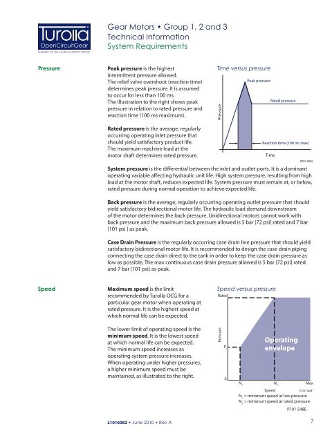
Pressure<br />
Peak pressure is the highest<br />
intermittent pressure allowed.<br />
The relief valve overshoot (reaction time)<br />
determines peak pressure. It is assumed<br />
to occur for less than 100 ms.<br />
The illustration to the right shows peak<br />
pressure in relation to rated pressure <strong>and</strong><br />
reaction time (100 ms maximum).<br />
Time versus pressure<br />
Pressure<br />
Peak pressure<br />
Rated pressure<br />
Rated pressure is the average, regularly<br />
occurring operating inlet pressure that<br />
should yield satisfactory product life.<br />
The maximum machine load at the<br />
motor shaft determines rated pressure.<br />
Reaction time (100 ms max)<br />
Time<br />
P005 006E<br />
System pressure is the differential between the inlet <strong>and</strong> outlet ports. It is a dominant<br />
operating variable affecting hydraulic unit life. High system pressure, resulting from high<br />
load at the motor shaft, reduces expected life. System pressure must remain at, or below,<br />
rated pressure during normal operation to achieve expected life.<br />
Back pressure is the average, regularly occurring operating outlet pressure that should<br />
yield satisfactory bidirectional motor life. The hydraulic load dem<strong>and</strong> downstream<br />
of the motor determines the back pressure. Unidirectional motors cannot work with<br />
back pressure <strong>and</strong> the maximum back pressure allowed is 5 bar [72 psi] rated <strong>and</strong> 7 bar<br />
[101 psi ] as peak.<br />
Case Drain Pressure is the regularly occurring case drain line pressure that should yield<br />
satisfactory bidirectional motor life. It is recommended to design the case drain piping<br />
connecting the case drain direct to the tank in order to keep the case drain pressure as<br />
low as possible. The max continuous case drain pressure allowed is 5 bar [72 psi] rated<br />
<strong>and</strong> 7 bar [101 psi] as peak.<br />
Speed<br />
Maximum speed is the limit<br />
recommended by Turolla OCG for a<br />
particular gear motor when operating at<br />
rated pressure. It is the highest speed at<br />
which normal life can be expected.<br />
Speed versus pressure<br />
Rated<br />
The lower limit of operating speed is the<br />
minimum speed. It is the lowest speed<br />
at which normal life can be expected.<br />
The minimum speed increases as<br />
operating system pressure increases.<br />
When operating under higher pressures,<br />
a higher minimum speed must be<br />
maintained, as illustrated to the right.<br />
Pressure<br />
P 1<br />
0<br />
N<br />
1<br />
Operating<br />
envelope<br />
N 2<br />
Max<br />
Speed<br />
P101 548E<br />
N 1<br />
= minimum speed at low pressure<br />
N 2<br />
= minimum speed at rated pressure<br />
P101 548E<br />
L1016082 • June 2010 • Rev A<br />
7