LCD-KIT Series - iEi
LCD-KIT Series - iEi
LCD-KIT Series - iEi

Create successful ePaper yourself
Turn your PDF publications into a flip-book with our unique Google optimized e-Paper software.
<strong>LCD</strong>-<strong>KIT</strong><br />
IEI Technology Corp.<br />
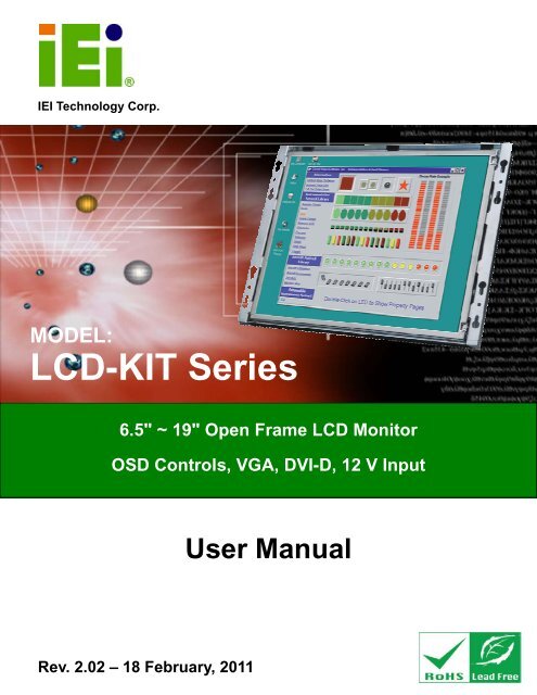
MODEL:<br />
<strong>LCD</strong>-<strong>KIT</strong> <strong>Series</strong><br />
6.5" ~ 19" Open Frame <strong>LCD</strong> Monitor<br />
OSD Controls, VGA, DVI-D, 12 V Input<br />
User Manual<br />
Rev. 2.02 – 18 February, 2011<br />
Page i
<strong>LCD</strong>-<strong>KIT</strong><br />
Revision<br />
Date Version Changes<br />
18 February, 2011 2.02 Updated dimension drawings<br />
15 December, 2010 2.01 Modified AV-6600 AD board information<br />
Modified Chapter 6 OSD Controls<br />
Modified Chapter 7 Software Driver<br />
17 June, 2010 2.00 Updated for <strong>LCD</strong>-<strong>KIT</strong>-R20 series<br />
30 September, 2009 1.13 Changed CN11 and CN12 pin definitions<br />
20 July, 2009 1.12 Updated OSD chapter<br />
31 May 2007 1.11 AV-5300 AD Board CN25 connector pin 3 voltage<br />
changed to +9V~+36V input<br />
30 April 2007 1.10 Updated Figure 1-4 and Section 4.4 for AV-5300 AD<br />
Board V2.0<br />
31 November 2006 1.00 Initial release<br />
Page ii
<strong>LCD</strong>-<strong>KIT</strong><br />
Copyright<br />
COPYRIGHT NOTICE<br />
The information in this document is subject to change without prior notice in order to<br />
improve reliability, design and function and does not represent a commitment on the part<br />
of the manufacturer.<br />
In no event will the manufacturer be liable for direct, indirect, special, incidental, or<br />
consequential damages arising out of the use or inability to use the product or<br />
documentation, even if advised of the possibility of such damages.<br />
This document contains proprietary information protected by copyright. All rights are<br />
reserved. No part of this manual may be reproduced by any mechanical, electronic, or<br />
other means in any form without prior written permission of the manufacturer.<br />
TRADEMARKS<br />
All registered trademarks and product names mentioned herein are used for identification<br />
purposes only and may be trademarks and/or registered trademarks of their respective<br />
owners.<br />
Page iii
<strong>LCD</strong>-<strong>KIT</strong><br />
Table of Contents<br />
1 INTRODUCTION.......................................................................................................... 1<br />
1.1 <strong>LCD</strong>-<strong>KIT</strong> SERIES <strong>LCD</strong> MONITOR OVERVIEW............................................................ 2<br />
1.1.1 Standard Features .............................................................................................. 2<br />
1.1.2 Model Variations................................................................................................ 2<br />
1.2 APPLICATIONS AND FEATURES.................................................................................... 3<br />
1.2.1 <strong>LCD</strong>-<strong>KIT</strong> <strong>Series</strong> <strong>LCD</strong> Monitor Applications ..................................................... 3<br />
1.2.2 <strong>LCD</strong>-<strong>KIT</strong> <strong>Series</strong> <strong>LCD</strong> Monitor Features............................................................ 3<br />
1.3 EXTERNAL OVERVIEW................................................................................................ 3<br />
1.3.1 Front View.......................................................................................................... 3<br />
1.3.2 Rear View ........................................................................................................... 4<br />
1.3.3 Connectors ......................................................................................................... 5<br />
1.3.4 AD Board ........................................................................................................... 6<br />
1.4 SERIES SPECIFICATIONS.............................................................................................. 7<br />
1.5 CERTIFICATIONS ......................................................................................................... 7<br />
2 MECHANICAL OVERVIEW ...................................................................................... 8<br />
2.1 INTRODUCTION........................................................................................................... 9<br />
2.2 REAR PANEL............................................................................................................... 9<br />
2.2.1 Rear Panel Variants ........................................................................................... 9<br />
2.2.2 Rear Panel Variant 1.......................................................................................... 9<br />
2.2.3 Rear Panel Variant 2........................................................................................ 10<br />
2.3 CONNECTOR PANEL...................................................................................................11<br />
2.3.1 Available Connectors ........................................................................................11<br />
2.3.2 Variant 1 Connectors ........................................................................................11<br />
2.3.3 Variant 2 Connectors ........................................................................................11<br />
2.3.4 Variant 3 Connectors ........................................................................................11<br />
2.3.5 Variant 4 Connectors ....................................................................................... 12<br />
2.4 PHYSICAL DIMENSIONS............................................................................................ 12<br />
2.4.1 General Physical Dimensions.......................................................................... 12<br />
2.4.2 <strong>LCD</strong>-<strong>KIT</strong>190G Physical Dimensions............................................................... 13<br />
2.4.3 <strong>LCD</strong>-<strong>KIT</strong>170GS Physical Dimensions............................................................. 14<br />
Page iv
<strong>LCD</strong>-<strong>KIT</strong><br />
2.4.4 <strong>LCD</strong>-<strong>KIT</strong>150G Physical Dimensions............................................................... 15<br />
2.4.5 <strong>LCD</strong>-<strong>KIT</strong>121G/GX Physical Dimensions ........................................................ 16<br />
2.4.6 <strong>LCD</strong>-<strong>KIT</strong>104GH Physical Dimensions............................................................ 17<br />
2.4.7 <strong>LCD</strong>-<strong>KIT</strong>84GH Physical Dimensions.............................................................. 18<br />
2.4.8 <strong>LCD</strong>-<strong>KIT</strong>65GH Physical Dimensions.............................................................. 19<br />
2.5 MOUNTING OPTIONS ................................................................................................ 20<br />
3 <strong>LCD</strong> SPECIFICATIONS ............................................................................................ 21<br />
3.1 <strong>LCD</strong> SPECIFICATIONS............................................................................................... 22<br />
3.1.1 <strong>LCD</strong> Overview ................................................................................................. 22<br />
3.1.2 <strong>LCD</strong>-<strong>KIT</strong>190G <strong>LCD</strong> Specifications ................................................................. 23<br />
3.1.3 <strong>LCD</strong>-<strong>KIT</strong>170G <strong>LCD</strong> Specifications ................................................................. 24<br />
3.1.4 <strong>LCD</strong>-<strong>KIT</strong>150G <strong>LCD</strong> Specifications ................................................................. 25<br />
3.1.5 <strong>LCD</strong>-<strong>KIT</strong>121GX <strong>LCD</strong> Specifications............................................................... 26<br />
3.1.6 <strong>LCD</strong>-<strong>KIT</strong>121G <strong>LCD</strong> Specifications ................................................................. 27<br />
3.1.7 <strong>LCD</strong>-<strong>KIT</strong>104GH <strong>LCD</strong> Specifications .............................................................. 28<br />
3.1.8 <strong>LCD</strong>-<strong>KIT</strong>84GH <strong>LCD</strong> Specifications ................................................................ 29<br />
3.1.9 <strong>LCD</strong>-<strong>KIT</strong>65GH <strong>LCD</strong> Specifications ................................................................ 30<br />
3.2 POWER ADAPTERS.................................................................................................... 31<br />
4 AD BOARDS ................................................................................................................ 32<br />
4.1 AD BOARD OVERVIEW............................................................................................. 33<br />
4.2 AV-9650 AD BOARD OVERVIEW.............................................................................. 33<br />
4.2.1 AV-9650 Peripheral Interface Connectors....................................................... 34<br />
4.2.2 AV-9650 Rear Panel Connectors ..................................................................... 34<br />
4.3 AV-6650 AD BOARD OVERVIEW.............................................................................. 35<br />
4.3.1 AV-6650 Peripheral Interface Connectors....................................................... 36<br />
4.3.2 AV-6650 Rear Panel Connectors ..................................................................... 36<br />
4.4 AV-6600 AD BOARD OVERVIEW.............................................................................. 36<br />
4.4.1 AV-6600 Peripheral Interface Connectors....................................................... 37<br />
4.4.2 AV-6600 Rear Panel Connectors ..................................................................... 38<br />
5 INSTALLATION ......................................................................................................... 39<br />
5.1 INSTALLATION PRECAUTIONS................................................................................... 40<br />
5.2 UNPACKING.............................................................................................................. 41<br />
5.2.1 Packaging ........................................................................................................ 41<br />
Page v
<strong>LCD</strong>-<strong>KIT</strong><br />
5.2.2 Unpacking Procedure ...................................................................................... 41<br />
5.2.3 Packing List ..................................................................................................... 42<br />
5.3 PRE-INSTALLATION PREPARATION ............................................................................ 42<br />
5.3.1 Tools ................................................................................................................. 42<br />
5.4 CONNECTORS ........................................................................................................... 43<br />
5.4.1 VGA Connector ................................................................................................ 43<br />
5.4.2 DVI-D Connector............................................................................................. 43<br />
5.4.3 12V Power Connector...................................................................................... 44<br />
5.5 MOUNTING THE <strong>LCD</strong>-<strong>KIT</strong> SERIES <strong>LCD</strong> MONITOR .................................................. 44<br />
6 OSD CONTROLS........................................................................................................ 45<br />
6.1 USER MODE OSD STRUCTURE................................................................................. 46<br />
6.1.1 OSD Buttons..................................................................................................... 46<br />
6.1.2 OSD Menu Structure ........................................................................................ 47<br />
6.2 USING THE OSD....................................................................................................... 48<br />
6.2.1 Main Display Features..................................................................................... 48<br />
6.2.2 Color ................................................................................................................ 49<br />
6.2.3 OSD Configurations......................................................................................... 50<br />
7 SOFTWARE DRIVER ................................................................................................ 51<br />
7.1 INTRODUCTION......................................................................................................... 52<br />
7.2 RS-232 OR USB TOUCH SCREEN ............................................................................. 52<br />
7.3 TOUCH PANEL DRIVER INSTALLATION...................................................................... 53<br />
7.4 CHANGE THE TOUCH SCREEN INTERFACE ................................................................ 56<br />
7.5 CALIBRATING THE TOUCH SCREEN........................................................................... 56<br />
A CERTIFICATIONS .................................................................................................... 59<br />
A.1 ROHS COMPLIANT .................................................................................................. 60<br />
B SAFETY PRECAUTIONS ......................................................................................... 61<br />
B.1 SAFETY PRECAUTIONS............................................................................................. 62<br />
B.1.1 General Safety Precautions ............................................................................. 62<br />
B.1.2 Anti-static Precautions .................................................................................... 63<br />
B.2 MAINTENANCE AND CLEANING PRECAUTIONS ........................................................ 63<br />
B.2.1 Maintenance and Cleaning.............................................................................. 63<br />
B.2.2 Cleaning Tools................................................................................................. 64<br />
Page vi
<strong>LCD</strong>-<strong>KIT</strong><br />
C SMARTOSD ................................................................................................................ 65<br />
C.1 IEI SMARTOSD QUICK INSTALLATION GUIDE ......................................................... 66<br />
C.2 PRE-INSTALLATION NOTICE ..................................................................................... 66<br />
C.3 SMARTOSD INSTALL ............................................................................................... 67<br />
C.4 SOFTWARE ILLUSTRATION ....................................................................................... 71<br />
C.4.1 Manage Page................................................................................................... 73<br />
C.4.2 EDID Page ...................................................................................................... 74<br />
C.4.3 Image Page...................................................................................................... 75<br />
C.4.4 Display Page (for analog signal).................................................................... 76<br />
C.4.5 Color Page ...................................................................................................... 77<br />
C.4.6 PIP Page.......................................................................................................... 78<br />
C.4.7 System Page..................................................................................................... 79<br />
C.4.8 About Page ...................................................................................................... 81<br />
C.5 SMARTOSD FAQ..................................................................................................... 82<br />
C.5.1 Windows 2000 Installation Failure ................................................................. 82<br />
C.5.2 Vista Installation Failure................................................................................. 83<br />
C.5.3 Model Failure.................................................................................................. 84<br />
C.5.4 DCC Port Failure............................................................................................ 84<br />
Page vii
<strong>LCD</strong>-<strong>KIT</strong><br />
List of Figures<br />
Figure 1-1: Typical <strong>LCD</strong>-<strong>KIT</strong> Front View .......................................................................................4<br />
Figure 1-2: Typical <strong>LCD</strong>-<strong>KIT</strong> Rear View ........................................................................................5<br />
Figure 1-3: Typical <strong>LCD</strong>-<strong>KIT</strong> Connectors .....................................................................................5<br />
Figure 1-4: AV-6600 AD Board ......................................................................................................6<br />
Figure 2-1: Rear Panel Variant 1 .................................................................................................10<br />
Figure 2-2: Rear Panel Variant 2 .................................................................................................10<br />
Figure 2-3: <strong>LCD</strong>-<strong>KIT</strong>190G Physical Dimensions (millimeters) .................................................13<br />
Figure 2-4: <strong>LCD</strong>-<strong>KIT</strong>170G Physical Dimensions (millimeters) .................................................14<br />
Figure 2-5: <strong>LCD</strong>-<strong>KIT</strong>150G Physical Dimensions (millimeters) .................................................15<br />
Figure 2-6: <strong>LCD</strong>-<strong>KIT</strong>121G/GX Physical Dimensions (millimeters) ...........................................16<br />
Figure 2-7: <strong>LCD</strong>-<strong>KIT</strong>104GH Physical Dimensions (millimeters)...............................................17<br />
Figure 2-8: <strong>LCD</strong>-<strong>KIT</strong>84GH Physical Dimensions (millimeters).................................................18<br />
Figure 2-9: <strong>LCD</strong>-<strong>KIT</strong>65GH Physical Dimensions (millimeters).................................................19<br />
Figure 4-1: AV-9650 AD Board Overview ...................................................................................33<br />
Figure 4-2: AV-6650 AD Board Overview ...................................................................................35<br />
Figure 4-3: AV-6600 AD Board Overview ...................................................................................37<br />
Figure 5-1: VGA Connector .........................................................................................................43<br />
Figure 5-2: DVI-D Connector .......................................................................................................44<br />
Figure 5-3: 12V Power Connector...............................................................................................44<br />
Figure 6-1: OSD Control Buttons (Except 6.5").........................................................................46<br />
Figure 6-2: <strong>LCD</strong>-<strong>KIT</strong>65 OSD Control Buttons ............................................................................47<br />
Figure 6-3: Main Display Features ..............................................................................................48<br />
Figure 6-4: Color Options ............................................................................................................49<br />
Figure 6-5: OSD Configurations Menu .......................................................................................50<br />
Figure 7-1: Setup Icon..................................................................................................................53<br />
Figure 7-2: Welcome Screen .......................................................................................................54<br />
Figure 7-3: License Agreement ...................................................................................................54<br />
Figure 7-4: Initiate Install .............................................................................................................55<br />
Figure 7-5: Installation Starts ......................................................................................................55<br />
Figure 7-6: Finish Installation......................................................................................................56<br />
Page viii
<strong>LCD</strong>-<strong>KIT</strong><br />
Figure 7-7: PenMount Monitor Icon ............................................................................................57<br />
Figure 7-8: PenMount Monitor Popup Menu..............................................................................57<br />
Figure 7-9: Configuration Screen................................................................................................57<br />
Figure 7-10: Calibration Initiation Screen ..................................................................................58<br />
Figure 7-11: Calibration Screen ..................................................................................................58<br />
Figure C-1: smartOSD Installer ...................................................................................................67<br />
Figure C-2: smartOSD Welcome Screen ....................................................................................68<br />
Figure C-3: smartOSD Folder Select Screen .............................................................................68<br />
Figure C-4: smartOSD Confirm Installation ...............................................................................69<br />
Figure C-5: smartOSD Installation Progress .............................................................................69<br />
Figure C-6: smartOSD Installation Complete ............................................................................70<br />
Figure C-7: smartOSD Desktop Icon ..........................................................................................70<br />
Figure C-8: Manage Page.............................................................................................................73<br />
Figure C-9: EDID Page .................................................................................................................74<br />
Figure C-10: Image Page..............................................................................................................75<br />
Figure C-11: Display Page ...........................................................................................................76<br />
Figure C-12: Color Page...............................................................................................................77<br />
Figure C-13: PIP Page ..................................................................................................................78<br />
Figure C-14: System Page ...........................................................................................................79<br />
Figure C-15: About Page..............................................................................................................81<br />
Figure C-16: DLL Missing ............................................................................................................82<br />
Figure C-17: Windows Vista Error ..............................................................................................83<br />
Figure C-18: Install as Administrator..........................................................................................83<br />
Figure C-19: Firmware Incompatibility .......................................................................................84<br />
Figure C-20: DCC Port Failure.....................................................................................................84<br />
Page ix
<strong>LCD</strong>-<strong>KIT</strong><br />
List of Tables<br />
Table 1-1: <strong>LCD</strong>-<strong>KIT</strong> <strong>Series</strong> Specifications ....................................................................................7<br />
Table 2-1: Rear Panel Variants ......................................................................................................9<br />
Table 2-2: General Physical Dimensions ...................................................................................12<br />
Table 2-3: Mounting Holes...........................................................................................................20<br />
Table 3-1: <strong>LCD</strong>-<strong>KIT</strong>190G <strong>LCD</strong> Specifications.............................................................................23<br />
Table 3-2: <strong>LCD</strong>-<strong>KIT</strong>170G <strong>LCD</strong> Specifications.............................................................................24<br />
Table 3-3: <strong>LCD</strong>-<strong>KIT</strong>150G <strong>LCD</strong> Specifications.............................................................................25<br />
Table 3-4: <strong>LCD</strong>-<strong>KIT</strong>121GX <strong>LCD</strong> Specifications ..........................................................................26<br />
Table 3-5: <strong>LCD</strong>-<strong>KIT</strong>121G <strong>LCD</strong> Specifications.............................................................................27<br />
Table 3-6: <strong>LCD</strong>-<strong>KIT</strong>104GH <strong>LCD</strong> Specifications ..........................................................................28<br />
Table 3-7: <strong>LCD</strong>-<strong>KIT</strong>84GH <strong>LCD</strong> Specifications ............................................................................29<br />
Table 3-8: <strong>LCD</strong>-<strong>KIT</strong>65GH <strong>LCD</strong> Specifications ............................................................................30<br />
Table 3-9: Power Adapter Specifications...................................................................................31<br />
Table 4-1: AV-9650 Peripheral Interface Connectors................................................................34<br />
Table 4-2: AV-9650 Rear Panel Connectors...............................................................................34<br />
Table 4-3: AV-6650 Peripheral Interface Connectors................................................................36<br />
Table 4-4: AV-6650 Rear Panel Connectors...............................................................................36<br />
Table 4-5: AV-6600 Peripheral Interface Connectors................................................................38<br />
Table 4-6: AV-6600 Rear Panel Connectors...............................................................................38<br />
Table 5-1: Rear Panel Connectors ..............................................................................................43<br />
Table 5-2: VGA Connector Pinouts.............................................................................................43<br />
Table 5-3: DVI-D Connector Pinouts...........................................................................................44<br />
Table 6-1: OSD Menus..................................................................................................................48<br />
Table C-1: SmartOSD Menu Structure........................................................................................72<br />
Page x
<strong>LCD</strong>-<strong>KIT</strong><br />
Chapter<br />
1<br />
1 Introduction<br />
Page 1
<strong>LCD</strong>-<strong>KIT</strong><br />
1.1 <strong>LCD</strong>-<strong>KIT</strong> <strong>Series</strong> <strong>LCD</strong> Monitor Overview<br />
The <strong>LCD</strong>-<strong>KIT</strong> series <strong>LCD</strong> monitor is the latest member of IEI’s line of sophisticated <strong>LCD</strong><br />
designs, and it has been improved to be RoHS compliant. It is designed to fit industrial<br />
automation, or any other applications that require minimum installation space and<br />
flexible configuration. Flexible analog or digital interfaces are provided for ease of<br />
connection with a management computer. If remote/non-attentive control is preferred,<br />
RS-232 or USB interfaces can be used with customized adapter cables.<br />
1.1.1 Standard Features<br />
All the base models listed in Section 1.2.1 have the following standard features<br />
• <strong>LCD</strong> monitor<br />
• OSD controls<br />
• VGA<br />
• Robust metal chassis<br />
• RoHS compliant<br />
1.1.2 Model Variations<br />
The <strong>LCD</strong>-<strong>KIT</strong> series offers the following model variations.<br />
• <strong>LCD</strong>-<strong>KIT</strong>65GH: 6.5” TFT <strong>LCD</strong><br />
• <strong>LCD</strong>-<strong>KIT</strong>84GH: 8.4” TFT <strong>LCD</strong><br />
• <strong>LCD</strong>-<strong>KIT</strong>84GHM: 8.4” TFT <strong>LCD</strong>, 9~36 V DC power input<br />
• <strong>LCD</strong>-<strong>KIT</strong>104GH: 10.4” TFT <strong>LCD</strong><br />
• <strong>LCD</strong>-<strong>KIT</strong>104GHM: 10.4” TFT <strong>LCD</strong>, 9~36 V DC power input<br />
• <strong>LCD</strong>-<strong>KIT</strong>121G: 12.1” TFT <strong>LCD</strong><br />
• <strong>LCD</strong>-<strong>KIT</strong>121GM: 12.1” TFT <strong>LCD</strong>, 9~36 V DC power input<br />
• <strong>LCD</strong>-<strong>KIT</strong>121GX: 12.1” TFT <strong>LCD</strong><br />
• <strong>LCD</strong>-<strong>KIT</strong>121GXM: 12.1” TFT <strong>LCD</strong>, 9~36 V DC power input<br />
• <strong>LCD</strong>-<strong>KIT</strong>150G: 15” TFT <strong>LCD</strong><br />
• <strong>LCD</strong>-<strong>KIT</strong>150GM: 15” TFT <strong>LCD</strong>, 9~36 V DC power input<br />
• <strong>LCD</strong>-<strong>KIT</strong>170GM: 17” TFT <strong>LCD</strong>, 9~36 V DC power input<br />
• <strong>LCD</strong>-<strong>KIT</strong>170GS: 17” TFT <strong>LCD</strong><br />
• <strong>LCD</strong>-<strong>KIT</strong>190G: 19” TFT <strong>LCD</strong><br />
Page 2
<strong>LCD</strong>-<strong>KIT</strong><br />
Page 3<br />
• <strong>LCD</strong>-<strong>KIT</strong>190GM: 19” TFT <strong>LCD</strong>, 9~36 V DC power input<br />
1.2 Applications and Features<br />
1.2.1 <strong>LCD</strong>-<strong>KIT</strong> <strong>Series</strong> <strong>LCD</strong> Monitor Applications<br />
IEI’s series of <strong>LCD</strong> monitors are designed for system manufacturers, integrators, or<br />
value-added resellers that want to provide all the performance, quality and reliability of an<br />
<strong>LCD</strong> display solution at a cost effective price. IEI’s <strong>LCD</strong> kits offer additional components<br />
such as cables, an inverter and power supply with controller interfaces that include VGA<br />
and DVI.<br />
1.2.2 <strong>LCD</strong>-<strong>KIT</strong> <strong>Series</strong> <strong>LCD</strong> Monitor Features<br />
Some of the features of the <strong>LCD</strong>-<strong>KIT</strong> series <strong>LCD</strong> monitor include:<br />
• Analog VGA interface supports most general system boards<br />
• Over 300 cd/m2 high brightness and 50,000 hrs MTFB long lifetime panel<br />
• Advanced thermal and air-flow design<br />
• Supports panel mounting<br />
• 12 V DC power input via adapter<br />
• M models have 9~36 V DC power connector<br />
• Long product life support<br />
• RoHS compliant<br />
1.3 External Overview<br />
The following sections describe the physical layout of the <strong>LCD</strong>-<strong>KIT</strong> series <strong>LCD</strong> monitors.<br />
1.3.1 Front View<br />
The front of the <strong>LCD</strong>-<strong>KIT</strong> series <strong>LCD</strong> monitor is a flat panel TFT <strong>LCD</strong> screen attached to a<br />
metal chassis. 3Figure 1-1 shows a typical <strong>LCD</strong>-<strong>KIT</strong> front view.
<strong>LCD</strong>-<strong>KIT</strong><br />
Figure 1-1: Typical <strong>LCD</strong>-<strong>KIT</strong> Front View<br />
1.3.2 Rear View<br />
The rear of the <strong>LCD</strong>-<strong>KIT</strong> series <strong>LCD</strong> monitor is a metal chassis. An on screen display<br />
(OSD) control button panel, if present, is located vertically on the left side of the chassis<br />
with the following control buttons:<br />
• <strong>LCD</strong> On/Off<br />
• Auto<br />
• Left<br />
• Right<br />
• Menu<br />
The OSD panel also has one power LED.<br />
3Figure 1-2 shows a typical <strong>LCD</strong>-<strong>KIT</strong> rear panel.<br />
Page 4
<strong>LCD</strong>-<strong>KIT</strong><br />
Page 5<br />
Figure 1-2: Typical <strong>LCD</strong>-<strong>KIT</strong> Rear View<br />
1.3.3 Connectors<br />
Each <strong>LCD</strong>-<strong>KIT</strong> series <strong>LCD</strong> monitor has a number of interface connectors on either the top<br />
or right panel of the chassis (when viewing the rear panel). 3Figure 1-3 shows a typical<br />
<strong>LCD</strong>-<strong>KIT</strong> connector panel. Each model may include or exclude additional connectors.<br />
Refer to Section 32.3 for listings of <strong>LCD</strong>-<strong>KIT</strong>s and their connectors. All connectors are fully<br />
described in Section 35.4.<br />
Figure 1-3: Typical <strong>LCD</strong>-<strong>KIT</strong> Connectors
<strong>LCD</strong>-<strong>KIT</strong><br />
1.3.4 AD Board<br />
The <strong>LCD</strong>-<strong>KIT</strong> series <strong>LCD</strong> monitor AD boards provide a wide variety of control interfaces,<br />
receiving and managing signals from a CPU card through cabling. 3Figure 1-4 shows the<br />
AV-6600 AD board as a sample of a typical AD board for the <strong>LCD</strong>-<strong>KIT</strong> series <strong>LCD</strong> monitor.<br />
Refer to Chapter 34 for a complete description of AD boards and their connectors.<br />
Figure 1-4: AV-6600 AD Board<br />
Page 6
1.4 <strong>Series</strong> Specifications<br />
The table below shows the <strong>LCD</strong>-<strong>KIT</strong> <strong>Series</strong> specifications.<br />
<strong>LCD</strong>-<strong>KIT</strong><br />
Page 7<br />
<strong>LCD</strong>-<strong>KIT</strong> 65GH 84GH 104GH 121G 121GX 150G 170G 190G<br />
<strong>LCD</strong> Type 6.5" TFT 8.4" TFT 10.4" TFT 12.1" TFT 12.1” TFT 15" TFT 17" TFT 19" TFT<br />
Input Interface VGA VGA + DVI-D<br />
Max.<br />
640x480 800x600 1024x768 1280x1024<br />
Resolution<br />
Backlight MTBF<br />
50,000 Hrs<br />
Contrast 600:1 700:1 800:1 1000:1<br />
<strong>LCD</strong> Color 262K 16.2M<br />
Brightness<br />
700 450 400 450 500 350 300<br />
(cd/m2)<br />
AD Board AV-9650 AV-6650 AV-6600<br />
Power<br />
Adapter<br />
36W 63000-FSP036RAB610-R<br />
50W TBD<br />
Chassis<br />
View Angle<br />
Heavy-duty steel<br />
160/140 160/160 140/125 170/160<br />
(H / V)<br />
OSD function<br />
Mounting<br />
Yes<br />
Panel<br />
Dimensions<br />
203 x<br />
234 x<br />
242.2 x<br />
294 x<br />
294 x<br />
364.1 x<br />
390.4 x<br />
427.9 x<br />
(WxHxD) (mm)<br />
121 x<br />
147 x<br />
209 x<br />
240.7 x<br />
240.7 x<br />
262.5 x<br />
300 x<br />
327.4 x<br />
34<br />
35.3<br />
33.6<br />
42<br />
42<br />
41.9<br />
46.9<br />
48.4<br />
Operating<br />
-10°C ~ 50°C<br />
Temperature<br />
Table 1-1: <strong>LCD</strong>-<strong>KIT</strong> <strong>Series</strong> Specifications<br />
1.5 Certifications<br />
All <strong>LCD</strong>-<strong>KIT</strong> series <strong>LCD</strong> monitor models comply with the following international standards:<br />
• RoHS<br />
For a more detailed description of these standards, please refer to Appendix A.
<strong>LCD</strong>-<strong>KIT</strong><br />
Chapter<br />
2<br />
2 Mechanical Overview<br />
Page 8
<strong>LCD</strong>-<strong>KIT</strong><br />
2.1 Introduction<br />
This chapter describes the general mechanical overview of the <strong>LCD</strong>-<strong>KIT</strong> series <strong>LCD</strong><br />
monitors including rear panel variations, available interfaces and overall dimensions.<br />
2.2 Rear Panel<br />
The rear panel of the <strong>LCD</strong>-<strong>KIT</strong> series <strong>LCD</strong> monitor is comprised of a metal chassis with an<br />
OSD control panel.<br />
2.2.1 Rear Panel Variants<br />
Page 9<br />
3Table 2-1 shows the rear panel variants for the <strong>LCD</strong>-<strong>KIT</strong> series <strong>LCD</strong> monitor.<br />
Model<br />
<strong>LCD</strong>-<strong>KIT</strong>190G<br />
<strong>LCD</strong>-<strong>KIT</strong>170G<br />
<strong>LCD</strong>-<strong>KIT</strong>150G<br />
<strong>LCD</strong>-<strong>KIT</strong>121GX<br />
<strong>LCD</strong>-<strong>KIT</strong>121G<br />
<strong>LCD</strong>-<strong>KIT</strong>104GH<br />
<strong>LCD</strong>-<strong>KIT</strong>84GH<br />
OSD Control Panel Location<br />
Vertically along the left side of the rear<br />
panel.<br />
Variant<br />
Number<br />
1<br />
<strong>LCD</strong>-<strong>KIT</strong>65GH In line along the bottom of the rear panel. 2<br />
Table 2-1: Rear Panel Variants<br />
2.2.2 Rear Panel Variant 1<br />
The following models of the <strong>LCD</strong>-<strong>KIT</strong> series <strong>LCD</strong> monitor have an OSD control panel<br />
located vertically along the left side of the rear panel:<br />
• <strong>LCD</strong>-<strong>KIT</strong>190G<br />
• <strong>LCD</strong>-<strong>KIT</strong>170G<br />
• <strong>LCD</strong>-<strong>KIT</strong>150G<br />
• <strong>LCD</strong>-<strong>KIT</strong>121GX<br />
• <strong>LCD</strong>-<strong>KIT</strong>121G
<strong>LCD</strong>-<strong>KIT</strong><br />
• <strong>LCD</strong>-<strong>KIT</strong>104GH<br />
• <strong>LCD</strong>-<strong>KIT</strong>84GH<br />
3Figure 2-1 shows the location of the rear panel variant 1 OSD controls.<br />
Figure 2-1: Rear Panel Variant 1<br />
2.2.3 Rear Panel Variant 2<br />
The following model of the <strong>LCD</strong>-<strong>KIT</strong> series <strong>LCD</strong> monitor has OSD control buttons located<br />
on the bottom of the rear panel:<br />
• <strong>LCD</strong>-<strong>KIT</strong>65GH<br />
3Figure 2-2 shows the location of the rear panel variant 2 OSD controls.<br />
Figure 2-2: Rear Panel Variant 2<br />
Page 10
<strong>LCD</strong>-<strong>KIT</strong><br />
2.3 Connector Panel<br />
All external peripheral interface connectors are located on the rear panel of the <strong>LCD</strong>-<strong>KIT</strong><br />
series <strong>LCD</strong> monitor. The following sections describe the rear panel variants and their<br />
associated connectors.<br />
2.3.1 Available Connectors<br />
Page 11<br />
There are a number of rear panel peripheral device connectors available for the <strong>LCD</strong>-<strong>KIT</strong><br />
series <strong>LCD</strong> monitor.<br />
• VGA connector<br />
• DVI-D connector<br />
• 12 V DC power connector<br />
• 9~36 V DC power connector<br />
2.3.2 Variant 1 Connectors<br />
The following is a list of the bottom panel peripheral device connectors used on the<br />
<strong>LCD</strong>-<strong>KIT</strong>65GH, <strong>LCD</strong>-<strong>KIT</strong>84GH and <strong>LCD</strong>-<strong>KIT</strong>104GH series <strong>LCD</strong> monitor.<br />
• VGA connector<br />
• 12 V DC power connector<br />
2.3.3 Variant 2 Connectors<br />
The following is a list of the bottom panel peripheral device connectors used on the<br />
<strong>LCD</strong>-<strong>KIT</strong>121GX, <strong>LCD</strong>-<strong>KIT</strong>150G, <strong>LCD</strong>-<strong>KIT</strong>170GS and <strong>LCD</strong>-<strong>KIT</strong>190G series <strong>LCD</strong> monitor.<br />
• VGA connector<br />
• DVI-D connector<br />
• 12 V DC power connector<br />
2.3.4 Variant 3 Connectors<br />
The following is a list of the bottom panel peripheral device connectors used on the<br />
<strong>LCD</strong>-<strong>KIT</strong>84GHM and <strong>LCD</strong>-<strong>KIT</strong>104GHM series <strong>LCD</strong> monitor.<br />
• VGA connector
<strong>LCD</strong>-<strong>KIT</strong><br />
• 9~36 V DC power connector<br />
2.3.5 Variant 4 Connectors<br />
The following is a list of the bottom panel peripheral device connectors used on the<br />
<strong>LCD</strong>-<strong>KIT</strong>121GXM, <strong>LCD</strong>-<strong>KIT</strong>150GM, <strong>LCD</strong>-<strong>KIT</strong>170GM and <strong>LCD</strong>-<strong>KIT</strong>190GM series <strong>LCD</strong><br />
monitor.<br />
• VGA connector<br />
• DVI-D connector<br />
• 9~36 V DC power connector<br />
2.4 Physical Dimensions<br />
The following sections describe the physical dimensions for each model of the <strong>LCD</strong>-<strong>KIT</strong><br />
series <strong>LCD</strong> monitor.<br />
2.4.1 General Physical Dimensions<br />
General physical dimensions for the <strong>LCD</strong>-<strong>KIT</strong> series <strong>LCD</strong> monitors are shown in 3Table<br />
2-2.<br />
Model Width (mm) Height (mm) Depth (mm)<br />
<strong>LCD</strong>-<strong>KIT</strong>190G 427.9 327.0 48.7<br />
<strong>LCD</strong>-<strong>KIT</strong>170GS 390.4 299.6 46.3<br />
<strong>LCD</strong>-<strong>KIT</strong>150G 364.1 262.1 41.3<br />
<strong>LCD</strong>-<strong>KIT</strong>121G/GX 294.0 240.7 41.3<br />
<strong>LCD</strong>-<strong>KIT</strong>104GH 244.5 209.0 43.4<br />
<strong>LCD</strong>-<strong>KIT</strong>84GH 234.0 147.0 44.0<br />
<strong>LCD</strong>-<strong>KIT</strong>65GH 203.4 121.0 34.0<br />
Table 2-2: General Physical Dimensions<br />
Page 12
<strong>LCD</strong>-<strong>KIT</strong><br />
Page 13<br />
2.4.2 <strong>LCD</strong>-<strong>KIT</strong>190G Physical Dimensions<br />
The physical dimensions of the <strong>LCD</strong>-<strong>KIT</strong>190G are shown in 3Figure 2-3.<br />
Figure 2-3: <strong>LCD</strong>-<strong>KIT</strong>190G Physical Dimensions (millimeters)
<strong>LCD</strong>-<strong>KIT</strong><br />
2.4.3 <strong>LCD</strong>-<strong>KIT</strong>170GS Physical Dimensions<br />
The physical dimensions of the <strong>LCD</strong>-<strong>KIT</strong>170GS are shown in 3Figure 2-4.<br />
Figure 2-4: <strong>LCD</strong>-<strong>KIT</strong>170G Physical Dimensions (millimeters)<br />
Page 14
<strong>LCD</strong>-<strong>KIT</strong><br />
Page 15<br />
2.4.4 <strong>LCD</strong>-<strong>KIT</strong>150G Physical Dimensions<br />
The physical dimensions of the <strong>LCD</strong>-<strong>KIT</strong>150G are shown in 3Figure 2-5.<br />
Figure 2-5: <strong>LCD</strong>-<strong>KIT</strong>150G Physical Dimensions (millimeters)
<strong>LCD</strong>-<strong>KIT</strong><br />
2.4.5 <strong>LCD</strong>-<strong>KIT</strong>121G/GX Physical Dimensions<br />
The physical dimensions of the <strong>LCD</strong>-<strong>KIT</strong>121G/GX are shown in 3Figure 2-6.<br />
Figure 2-6: <strong>LCD</strong>-<strong>KIT</strong>121G/GX Physical Dimensions (millimeters)<br />
Page 16
<strong>LCD</strong>-<strong>KIT</strong><br />
Page 17<br />
2.4.6 <strong>LCD</strong>-<strong>KIT</strong>104GH Physical Dimensions<br />
The physical dimensions of the <strong>LCD</strong>-<strong>KIT</strong>104GH are shown in 3Figure 2-7.<br />
Figure 2-7: <strong>LCD</strong>-<strong>KIT</strong>104GH Physical Dimensions (millimeters)
<strong>LCD</strong>-<strong>KIT</strong><br />
2.4.7 <strong>LCD</strong>-<strong>KIT</strong>84GH Physical Dimensions<br />
The physical dimensions of the <strong>LCD</strong>-<strong>KIT</strong>84GH are shown in 4Figure 2-8.<br />
Figure 2-8: <strong>LCD</strong>-<strong>KIT</strong>84GH Physical Dimensions (millimeters)<br />
Page 18
<strong>LCD</strong>-<strong>KIT</strong><br />
Page 19<br />
2.4.8 <strong>LCD</strong>-<strong>KIT</strong>65GH Physical Dimensions<br />
The physical dimensions of the <strong>LCD</strong>-<strong>KIT</strong>65GH are shown in 4Figure 2-9.<br />
Figure 2-9: <strong>LCD</strong>-<strong>KIT</strong>65GH Physical Dimensions (millimeters)
<strong>LCD</strong>-<strong>KIT</strong><br />
2.5 Mounting Options<br />
Each <strong>LCD</strong>-<strong>KIT</strong> series <strong>LCD</strong> monitor has mounting holes located on the mounting bracket.<br />
4Table 2-3 details the number of mounting holes for each model of the <strong>LCD</strong>-<strong>KIT</strong> series <strong>LCD</strong><br />
monitor. Refer to Section 42.4 for more information.<br />
Model No. of Round Holes - Size No. of Slotted Holes<br />
<strong>LCD</strong>-<strong>KIT</strong>190G 6 – 4 mm diameter 8<br />
<strong>LCD</strong>-<strong>KIT</strong>170G 6 – 4.5 mm diameter 8<br />
<strong>LCD</strong>-<strong>KIT</strong>150G 6 – 4.5 mm diameter 8<br />
<strong>LCD</strong>-<strong>KIT</strong>121G/GX 4 – 3.5 mm diameter -<br />
<strong>LCD</strong>-<strong>KIT</strong>104GH 4 – 3.5 mm diameter -<br />
<strong>LCD</strong>-<strong>KIT</strong>84GH 4 – 3.5 mm diameter 4<br />
<strong>LCD</strong>-<strong>KIT</strong>65GH 4 – 3.5 mm diameter 4<br />
Table 2-3: Mounting Holes<br />
Page 20
<strong>LCD</strong>-<strong>KIT</strong><br />
Chapter<br />
3<br />
3 <strong>LCD</strong> Specifications<br />
Page 21
<strong>LCD</strong>-<strong>KIT</strong><br />
3.1 <strong>LCD</strong> Specifications<br />
3.1.1 <strong>LCD</strong> Overview<br />
The <strong>LCD</strong>-<strong>KIT</strong> series industrial <strong>LCD</strong> monitors use the following <strong>LCD</strong> panels.<br />
• <strong>LCD</strong>-<strong>KIT</strong>190G: HANNSTAR/HSD190MEN3-A<br />
• <strong>LCD</strong>-<strong>KIT</strong>170G: AUO G170EG01 V0<br />
• <strong>LCD</strong>-<strong>KIT</strong>150G: AUO G150XG01 V1<br />
• <strong>LCD</strong>-<strong>KIT</strong>121GX: AUO G121XN01 V0<br />
• <strong>LCD</strong>-<strong>KIT</strong>121G: AUO G121SN01 V4<br />
• <strong>LCD</strong>-<strong>KIT</strong>104GH: AUO/G104SN02 V2<br />
• <strong>LCD</strong>-<strong>KIT</strong>084GH: AUO/G084SN05 V8<br />
• <strong>LCD</strong>-<strong>KIT</strong>65GH: AUO/G065VN01 V2<br />
Detailed specifications for the <strong>LCD</strong> screens are listed in the following sections.<br />
Page 22
<strong>LCD</strong>-<strong>KIT</strong><br />
Page 23<br />
3.1.2 <strong>LCD</strong>-<strong>KIT</strong>190G <strong>LCD</strong> Specifications<br />
The table below lists the <strong>LCD</strong>-<strong>KIT</strong>190G <strong>LCD</strong> specifications.<br />
Model<br />
<strong>LCD</strong>-<strong>KIT</strong>190G<br />
Size 19”<br />
MFR/Model<br />
HANNSTAR/HSD190MEN3<br />
-A<br />
Resolution SXGA (1280 x 1024)<br />
Active Area (mm) 376.32 x 301.06<br />
Pixel Pitch (mm) 0.294<br />
Mode<br />
TN<br />
Number of Colors 16.7M<br />
Color Saturation (NTSC%) 72<br />
View Angle (H/V) 170 / 160<br />
Brightness (cd/m2) 300<br />
Contrast Ratio 1000:1<br />
Response Time (ms) (at 25C) 5<br />
Interface<br />
2ch LVDS<br />
Supply Voltage (V) 5<br />
Backlight<br />
4 CCFL<br />
Table 3-1: <strong>LCD</strong>-<strong>KIT</strong>190G <strong>LCD</strong> Specifications
<strong>LCD</strong>-<strong>KIT</strong><br />
3.1.3 <strong>LCD</strong>-<strong>KIT</strong>170G <strong>LCD</strong> Specifications<br />
The table below lists the <strong>LCD</strong>-<strong>KIT</strong>170G <strong>LCD</strong> specifications.<br />
Model<br />
<strong>LCD</strong>-<strong>KIT</strong>170G<br />
Size 17”<br />
MFR/Model<br />
AUO/G170EG01 V0<br />
Resolution SXGA (1280 x 1024)<br />
Active Area (mm) 337.9 x 270.3<br />
Pixel Pitch (mm) 0.264<br />
Mode<br />
TN<br />
Number of Colors 16.7M<br />
Color Saturation (NTSC%) 72<br />
View Angle (H/V) 170/160<br />
Brightness (cd/m2) 350<br />
Contrast Ratio 800:1<br />
Response Time (ms) (at 25C) 8<br />
Power Consumption (W) 25.2<br />
Interface<br />
2ch LVDS<br />
Supply Voltage (V) 5<br />
Backlight<br />
4 CCFL<br />
Lamp Life (hrs) 50,000<br />
Table 3-2: <strong>LCD</strong>-<strong>KIT</strong>170G <strong>LCD</strong> Specifications<br />
Page 24
<strong>LCD</strong>-<strong>KIT</strong><br />
Page 25<br />
3.1.4 <strong>LCD</strong>-<strong>KIT</strong>150G <strong>LCD</strong> Specifications<br />
The table below lists the <strong>LCD</strong>-<strong>KIT</strong>150G <strong>LCD</strong> specifications.<br />
Model<br />
<strong>LCD</strong>-<strong>KIT</strong>150G<br />
Size 15”<br />
MFR/Model<br />
Resolution<br />
AUO/G150XG01<br />
V1<br />
XGA (1024 x<br />
768)<br />
Active Area (mm) 304.1 x 228.1<br />
Pixel Pitch (mm) 0.297<br />
Mode<br />
TN<br />
Number of Colors 16.2M<br />
Color Saturation (NTSC%) 65<br />
View Angle (H/V) 140/120<br />
Brightness (cd/m2) 350<br />
Contrast Ratio 700:1<br />
Response Time (ms) (at 25C) 8<br />
Power Consumption (W) 8.9<br />
Interface<br />
1ch LVDS<br />
Supply Voltage (V) 3.3<br />
Backlight<br />
2 CCFL<br />
Lamp Life (hrs) 50000<br />
Table 3-3: <strong>LCD</strong>-<strong>KIT</strong>150G <strong>LCD</strong> Specifications
<strong>LCD</strong>-<strong>KIT</strong><br />
3.1.5 <strong>LCD</strong>-<strong>KIT</strong>121GX <strong>LCD</strong> Specifications<br />
The table below lists the <strong>LCD</strong>-<strong>KIT</strong>121GX <strong>LCD</strong> specifications.<br />
Model<br />
<strong>LCD</strong>-<strong>KIT</strong>121GX<br />
Size 12.1”<br />
MFR/Model<br />
AUO/G121XN01 V0<br />
Resolution SVGA (1024 x 768)<br />
Active Area (mm) 245.76 x 184.32<br />
Pixel Pitch (mm) 0.3075<br />
Mode<br />
Number of Colors<br />
TN<br />
262K<br />
View Angle (H/V) 160/160<br />
Brightness (cd/m2) 500<br />
Contrast Ratio 700:1<br />
Response Time (ms) (at 25C) 35<br />
Power Consumption (W) 9.15<br />
Interface<br />
1ch LVDS<br />
Supply Voltage (V) 3.3<br />
Backlight<br />
LED<br />
Color Saturation (NTSC%) 70<br />
Table 3-4: <strong>LCD</strong>-<strong>KIT</strong>121GX <strong>LCD</strong> Specifications<br />
Page 26
<strong>LCD</strong>-<strong>KIT</strong><br />
Page 27<br />
3.1.6 <strong>LCD</strong>-<strong>KIT</strong>121G <strong>LCD</strong> Specifications<br />
The table below lists the <strong>LCD</strong>-<strong>KIT</strong>121G <strong>LCD</strong> specifications.<br />
Model<br />
<strong>LCD</strong>-<strong>KIT</strong>121G<br />
Size 12.1”<br />
MFR/Model<br />
AUO/G121SN01 V4<br />
Resolution SVGA (800 x 600)<br />
Active Area (mm) 245.76 x 184.32<br />
Pixel Pitch (mm) 0.3075<br />
Mode<br />
Number of Colors<br />
TN<br />
262K<br />
View Angle (H/V) 160/140<br />
Brightness (cd/m2) 450<br />
Contrast Ratio 700:1<br />
Response Time (ms) (at 25C) 35<br />
Power Consumption (W) 6.7<br />
Interface<br />
1ch LVDS<br />
Supply Voltage (V) 3.3<br />
Backlight<br />
LED<br />
Color Saturation (NTSC%) 55<br />
Table 3-5: <strong>LCD</strong>-<strong>KIT</strong>121G <strong>LCD</strong> Specifications
<strong>LCD</strong>-<strong>KIT</strong><br />
3.1.7 <strong>LCD</strong>-<strong>KIT</strong>104GH <strong>LCD</strong> Specifications<br />
The table below lists the <strong>LCD</strong>-<strong>KIT</strong>104GH <strong>LCD</strong> specifications.<br />
Model<br />
<strong>LCD</strong>-<strong>KIT</strong>104GH<br />
Size 10.4”<br />
MFR/Model<br />
AUO/G104SN02 V2<br />
Resolution SVGA (800 x 600)<br />
Active Area (mm) 211.2 x 158.4<br />
Pixel Pitch (mm) 0.264<br />
Mode<br />
Number of Colors<br />
TN<br />
262K<br />
View Angle (H/V) 160 / 140<br />
Brightness (cd/m2) 400<br />
Contrast Ratio 700:1<br />
Response Time (ms) (at 25C) 30<br />
Power Consumption (W) 5.2<br />
Interface<br />
1ch LVDS<br />
Supply Voltage (V) 3.3<br />
Backlight<br />
LED<br />
Color Saturation (NTSC%) 45<br />
Table 3-6: <strong>LCD</strong>-<strong>KIT</strong>104GH <strong>LCD</strong> Specifications<br />
Page 28
<strong>LCD</strong>-<strong>KIT</strong><br />
Page 29<br />
3.1.8 <strong>LCD</strong>-<strong>KIT</strong>84GH <strong>LCD</strong> Specifications<br />
The table below lists the <strong>LCD</strong>-<strong>KIT</strong>84GH <strong>LCD</strong> specifications.<br />
Model<br />
<strong>LCD</strong>-<strong>KIT</strong>84GH<br />
Size 8.4”<br />
MFR/Model<br />
AUO/G084SN05 V8<br />
Resolution SVGA (800 x 600)<br />
Active Area (mm) 170.4 x 127.8<br />
Pixel Pitch (mm) 0.213<br />
Mode<br />
Number of Colors<br />
TN<br />
262K<br />
View Angle (H/V) 160 / 140<br />
Brightness (cd/m2) 450<br />
Contrast Ratio 600:1<br />
Response Time (ms) (at 25C) 30<br />
Power Consumption (W) 4.2<br />
Interface<br />
LVDS<br />
Supply Voltage (V) 3.3<br />
Backlight<br />
LED<br />
Color Saturation (NTSC%) 45<br />
Table 3-7: <strong>LCD</strong>-<strong>KIT</strong>84GH <strong>LCD</strong> Specifications
<strong>LCD</strong>-<strong>KIT</strong><br />
3.1.9 <strong>LCD</strong>-<strong>KIT</strong>65GH <strong>LCD</strong> Specifications<br />
The table below lists the <strong>LCD</strong>-<strong>KIT</strong>65GH <strong>LCD</strong> specifications.<br />
Model<br />
<strong>LCD</strong>-<strong>KIT</strong>65GH<br />
Size 6.5”<br />
MFR/Model<br />
AUO/G065VN01 V2<br />
Resolution VGA (640 x 480)<br />
Active Area (mm) 132.48 x 99.36<br />
Pixel Pitch (mm) 0.207<br />
Mode<br />
Number of Colors<br />
TN<br />
262K<br />
Color Saturation (NTSC%) 55<br />
View Angle (H/V) 160/140<br />
Brightness (cd/m2) 800<br />
Contrast Ratio 600:1<br />
Response Time (ms) (at 25C) 25<br />
Power Consumption (W) 3.86<br />
Interface<br />
LVDS<br />
Supply Voltage (V) 3.3<br />
Backlight<br />
LED<br />
Table 3-8: <strong>LCD</strong>-<strong>KIT</strong>65GH <strong>LCD</strong> Specifications<br />
Page 30
<strong>LCD</strong>-<strong>KIT</strong><br />
Page 31<br />
3.2 Power Adapters<br />
4Table 3-9 lists the AC/DC power adapter specifications.<br />
<strong>LCD</strong>-<strong>KIT</strong> 190G, 170G, 150G, 121G/XG 104GH, 84GH, 65GH<br />
Power 50 Watt AC/DC Adapter 35 Watt AC/DC Adapter<br />
General Description<br />
Universal Input 90 to 264 VAC<br />
EMI Meets FCC/CISPR 22 Class B<br />
MTBF 165Khrs<br />
Limited Power Source<br />
Universal Input 90 to 264 VAC<br />
EMI Meets FCC/CISPR 22 Class B<br />
MTBF 300Khrs<br />
Limited Power Source<br />
Input Voltage Range 90-264VAC 90-264VAC<br />
Input Frequency 47-63 Hz 47-63 Hz<br />
Inrush Current 40A max. (Cold Start) 30A max. (Cold Start)<br />
Hold-up Time 10mS typical 10mS typical<br />
Leakage Current 0.5mA max. 3.5mA max.<br />
Short Circuit Protection Continuous Continuous<br />
Over-voltage Protection Yes Yes<br />
Continuous Output Power 50W max. 35W max.<br />
Hi-pot Isolation:<br />
Input / Output<br />
4242VDC<br />
4242VDC<br />
Table 3-9: Power Adapter Specifications
<strong>LCD</strong>-<strong>KIT</strong><br />
Chapter<br />
4<br />
4 AD Boards<br />
Page 32
<strong>LCD</strong>-<strong>KIT</strong><br />
4.1 AD Board Overview<br />
The <strong>LCD</strong>-<strong>KIT</strong> series industrial <strong>LCD</strong> monitor AD board provides a wide variety of control<br />
interfaces, receiving and managing interface signals from a CPU card through cabling.<br />
There are three AD boards used for the <strong>LCD</strong>-<strong>KIT</strong> series <strong>LCD</strong> monitors: AV-9650, AV-6650<br />
and AV-6600. Refer to Section 41.4 for a listing of <strong>LCD</strong>-<strong>KIT</strong> series <strong>LCD</strong> monitors and their<br />
associated AD board. The following sections describe each AD board in detail.<br />
4.2 AV-9650 AD Board Overview<br />
Page 33<br />
Figure 4-1: AV-9650 AD Board Overview
<strong>LCD</strong>-<strong>KIT</strong><br />
4.2.1 AV-9650 Peripheral Interface Connectors<br />
4Table 4-1 shows a list of the peripheral interface connectors on the AV-9650 AD board.<br />
Connector Type Label<br />
Auto-dimming connector 6-pin wafer connector CN7<br />
Backlight Inverter connector 4-pin wafer connector CN16<br />
Debug port connector 4-pin wafer connector CN9<br />
External OSD and<br />
LED indication connector<br />
9-pin wafer connector<br />
CN10<br />
LVDS connector 30-pin crimp connector CN15<br />
Power input connector 3-pin connector CN2<br />
Power output connector 2-pin wafer connector CN4<br />
USB signal input connector 4-pin wafer connector CN17<br />
Touchscreen connector 9-pin wafer connector J4<br />
VGA connector 10-pin box header CN14<br />
Table 4-1: AV-9650 Peripheral Interface Connectors<br />
4.2.2 AV-9650 Rear Panel Connectors<br />
4Table 4-2 lists the rear panel connectors and buttons on the AV-9650 AD board.<br />
Connector Type Label<br />
DC 12V power connector DC Power Jack CN13<br />
Serial port connector RS-232 connector J7<br />
OSD function button Pushbutton S1<br />
OSD function button Pushbutton S2<br />
OSD function button Pushbutton S3<br />
OSD function button Pushbutton S4<br />
VGA connector 15-pin VGA connector VGA1<br />
Table 4-2: AV-9650 Rear Panel Connectors<br />
Page 34
<strong>LCD</strong>-<strong>KIT</strong><br />
Page 35<br />
4.3 AV-6650 AD Board Overview<br />
Figure 4-2: AV-6650 AD Board Overview
<strong>LCD</strong>-<strong>KIT</strong><br />
4.3.1 AV-6650 Peripheral Interface Connectors<br />
4Table 4-3 shows a list of the peripheral interface connectors on the AV-6650 AD board.<br />
Connector Type Label<br />
Auto-dimming connector 6-pin wafer connector CN7<br />
Backlight inverter connector 6-pin wafer connector CN6<br />
Debug port connector 4-pin wafer connector CN9<br />
External OSD and<br />
LED indication connector<br />
9-pin wafer connector<br />
CN10<br />
LVDS output connector 30-pin connector CN5<br />
Power output connector 2-pin header CN4<br />
Power input connector 3-pin connector CN2<br />
RS-232 and USB signal input<br />
connector<br />
12-pin wafer connector<br />
CN14<br />
Touchscreen connector 9-pin wafer connector J4<br />
VGA connector 10-pin box header VGA2<br />
Table 4-3: AV-6650 Peripheral Interface Connectors<br />
4.3.2 AV-6650 Rear Panel Connectors<br />
4Table 4-4 lists the rear panel connectors and jumpers on the AV-6650 AD board.<br />
Connector Type Label<br />
DC 12V power connector DC Power Jack CN13<br />
VGA connector 15-pin VGA connector VGA1<br />
Table 4-4: AV-6650 Rear Panel Connectors<br />
4.4 AV-6600 AD Board Overview<br />
The AV-6600 AD board provides a wide variety of control interfaces, receiving and<br />
managing interface signals from a CPU card through cabling. The following sections<br />
describe the AV-6600 AD board in detail.<br />
Page 36
<strong>LCD</strong>-<strong>KIT</strong><br />
Page 37<br />
Figure 4-3: AV-6600 AD Board Overview<br />
4.4.1 AV-6600 Peripheral Interface Connectors<br />
4Table 4-5 shows a list of the peripheral interface connectors on the AV-6600 AD board.<br />
Connector Type Label<br />
Audio input connector 4-pin wafer connector CN11<br />
Audio speaker output connector 4-pin wafer connector CN12<br />
Auto-dimming connector 6-pin wafer connector CN7<br />
Debug connector 4-pin wafer connector CN9<br />
External OSD and LED indication connector 9-pin wafer connector CN10
<strong>LCD</strong>-<strong>KIT</strong><br />
Infrared connector 6-pin wafer connector CN8<br />
Inverter interface connector 6-pin wafer connector CN6<br />
LVDS connector 30-pin connector CN5<br />
Power output connector (+12 V) 2-pin wafer connector CN3<br />
Power output connector (+5 V) 2-pin wafer connector CN4<br />
Power input connector 3-pin connector CN2<br />
RS-232 and USB signal input connector 12-pin wafer connector CN14<br />
Touchscreen connector 9-pin wafer connector J4<br />
VGA connector 10-pin box header VGA2<br />
Table 4-5: AV-6600 Peripheral Interface Connectors<br />
4.4.2 AV-6600 Rear Panel Connectors<br />
4Table 4-6 lists the rear panel connectors on the AV-6600 AD board.<br />
Connector Type Label<br />
12V DC power connector DC Power Jack CN13<br />
DVI connector 24-pin DVI-D connector J2<br />
VGA connector 15-pin VGA connector VGA1<br />
Table 4-6: AV-6600 Rear Panel Connectors<br />
Page 38
<strong>LCD</strong>-<strong>KIT</strong><br />
Chapter<br />
5<br />
5 Installation<br />
Page 39
<strong>LCD</strong>-<strong>KIT</strong><br />
5.1 Installation Precautions<br />
When installing the <strong>LCD</strong>-<strong>KIT</strong> series <strong>LCD</strong> monitor, please follow the precautions listed<br />
below:<br />
• Read the user manual: The user manual provides a complete description of<br />
the <strong>LCD</strong>-<strong>KIT</strong> series <strong>LCD</strong> monitor, installation instructions and configuration<br />
options.<br />
• DANGER! Disconnect Power: Power to the <strong>LCD</strong> monitor must be<br />
disconnected when installing the <strong>LCD</strong>-<strong>KIT</strong> series <strong>LCD</strong> monitor, or before any<br />
attempt is made to access the rear panel. Electric shock and personal injury<br />
might occur if the rear panel of the monitor is opened while the power cord is<br />
still connected to an electrical outlet.<br />
• Qualified Personnel: The <strong>LCD</strong>-<strong>KIT</strong> series <strong>LCD</strong> monitor must be installed and<br />
operated only by trained and qualified personnel. Maintenance, upgrades, or<br />
repairs may only be carried out by qualified personnel who are familiar with<br />
the associated dangers.<br />
• Mounting: Since the monitor may weigh up to 10 kg (not including a swing<br />
arm or other accessories), please ensure at least two people assist with<br />
mounting the monitor.<br />
• Air Circulation: Make sure there is sufficient air circulation when installing the<br />
monitor. The monitor’s cooling vents must not be obstructed by any objects.<br />
Blocking the vents can cause overheating of the monitor. Leave at least 5 cm<br />
of clearance around the monitor to prevent overheating.<br />
• Grounding: The monitor should be properly grounded. The voltage feeds<br />
must not be overloaded. Adjust the cabling and provide external overcharge<br />
protection per the electrical values indicated on the label attached to the back<br />
of the monitor.<br />
• Anti-static Discharge: The rear panel of the monitor must to be removed to<br />
configure the monitor’s AD board voltage select jumper. When doing so, be<br />
sure the monitor is disconnected from its power source and take all necessary<br />
safety precautions to avoid electrocution and static discharge to the AD board.<br />
The use of a grounded wrist strap and an anti-static work pad is<br />
recommended.<br />
Page 40
5.2 Unpacking<br />
5.2.1 Packaging<br />
<strong>LCD</strong>-<strong>KIT</strong><br />
placed with the monitor in the internal (first) box.<br />
5.2.2 Unpacking Procedure<br />
Page 41<br />
When shipped, the <strong>LCD</strong>-<strong>KIT</strong> series <strong>LCD</strong> monitor is wrapped in a plastic bag. Two<br />
polystyrene ends are placed on either side of the monitor. The monitor is then placed into<br />
a first (internal) cardboard box. This box is then sealed and placed into a second (external)<br />
cardboard box. The second box is also sealed. A bag containing accessory items is<br />
To unpack the <strong>LCD</strong>-<strong>KIT</strong> series <strong>LCD</strong> monitor, follow the steps below:<br />
WARNING:<br />
The front side <strong>LCD</strong> screen has a protective plastic cover stuck to the<br />
screen. Only remove the plastic cover after the <strong>LCD</strong>-<strong>KIT</strong> series <strong>LCD</strong><br />
monitor has been properly installed. This ensures the screen is<br />
protected during the installation process.<br />
Step 1: Use box cutters, a knife or a sharp pair of scissors that seals the top side of the<br />
external (second) box.<br />
Step 2: Open the external (second) box.<br />
Step 3: Use box cutters, a knife or a sharp pair of scissors that seals the top side of the<br />
internal (first) box.<br />
Step 4: Lift the monitor out of the boxes.<br />
Step 5: Remove both polystyrene ends, one from each side.<br />
Step 6: Pull the plastic cover off the <strong>LCD</strong>-<strong>KIT</strong> series <strong>LCD</strong> monitor.<br />
Step 7: Make sure all the components listed in the packing list are present. Step 0:
<strong>LCD</strong>-<strong>KIT</strong><br />
5.2.3 Packing List<br />
All the monitors in the <strong>LCD</strong>-<strong>KIT</strong> series are shipped with the following components:<br />
• 1 x <strong>LCD</strong>-<strong>KIT</strong> series <strong>LCD</strong> monitor.<br />
• 1 x AC Power cable<br />
• 1 x VGA Cable<br />
• 1 x 50W AC Power Adapter (<strong>LCD</strong>-<strong>KIT</strong>190G / 170 / 150 / 121)<br />
• 1 x 35W AC Power Adapter (<strong>LCD</strong>-<strong>KIT</strong>104GH / 84 / 65)<br />
• 5 x Replacement Round Head Screw<br />
• 5 x Replacement Flat Head Screw<br />
• 5 x Replacement Wire Strain Band<br />
• 1 x User Manual on CDROM<br />
If any of these items are missing or damaged, contact the distributor or sales<br />
representative immediately.<br />
5.3 Pre-installation Preparation<br />
5.3.1 Tools<br />
Before installing the <strong>LCD</strong>-<strong>KIT</strong> series <strong>LCD</strong> monitor, make sure the following tools are on<br />
hand:<br />
• Philips (crosshead) screwdriver: All the retention screws on the system are<br />
Philips screws.<br />
• Soft working mat: When the <strong>LCD</strong>-<strong>KIT</strong> series <strong>LCD</strong> monitor is installed, the<br />
screen is placed on the working surface. It is therefore important to rest the<br />
MPC industrial workstation on a soft mat that cannot damage the <strong>LCD</strong> screen<br />
on the front of the <strong>LCD</strong>-<strong>KIT</strong> series <strong>LCD</strong> monitor.<br />
Page 42
5.4 Connectors<br />
4Table 5-1 lists the rear panel connectors for the <strong>LCD</strong>-<strong>KIT</strong> series <strong>LCD</strong> monitors.<br />
<strong>LCD</strong>-<strong>KIT</strong> 65GH 84GH 104GH 121G/GX 150G 170G 190G<br />
DVI-D - Yes<br />
VGA<br />
Power (12V Jack)<br />
Yes<br />
Yes<br />
Table 5-1: Rear Panel Connectors<br />
5.4.1 VGA Connector<br />
Use the rear panel standard 15-pin female VGA connector to connect the <strong>LCD</strong> monitor to<br />
the system graphics interface.<br />
Pin Description Pin Description Pin Description<br />
1 RED 6 GROUND 11 NC<br />
2 GREEN 7 GROUND 12 DDCDAT<br />
3 BLUE 8 GROUND 13 HSYNC<br />
4 NC 9 NC 14 VSYNC<br />
5 GROUND 10 GROUND 15 DDCCLK<br />
Table 5-2: VGA Connector Pinouts<br />
<strong>LCD</strong>-<strong>KIT</strong><br />
Page 43<br />
Figure 5-1: VGA Connector<br />
5.4.2 DVI-D Connector<br />
Use the rear panel standard 24-pin female DVI-D connector to connect the <strong>LCD</strong> monitor to<br />
the system graphics interface.
<strong>LCD</strong>-<strong>KIT</strong><br />
Pin Description Pin Description Pin Description<br />
1 TMDS Data2- 9 TMDS Data1- 17 TMDS Data0-<br />
2 TMDS Data2+ 10 TMDS Data1+ 18 TMDSData0+<br />
3 TMDS Data2/4 Shield 11 TMDS Data1/3 Shield 19 TMDS Data0/5 Shield<br />
4 TMDS Data4- 12 TMDS Data3- 20 TMDS Data5-<br />
5 TMDS Data4+ 13 TMDS Data3+ 21 TMDS Data5+<br />
6 DDC Clock [SCL] 14 +5 V Power 22 TMDS Clock Shield<br />
7 DDC Data [SDA] 15 Ground (for +5 V) 23 TMDS Clock +<br />
8 Analog vertical sync 16 Hot Plug Detect 24 TMDS Clock -<br />
Table 5-3: DVI-D Connector Pinouts<br />
Figure 5-2: DVI-D Connector<br />
5.4.3 12V Power Connector<br />
Use the rear panel +12V DC (or 9~36V DC on M models) jack to connect the monitor to a<br />
power source.<br />
Figure 5-3: 12V Power Connector<br />
5.5 Mounting the <strong>LCD</strong>-<strong>KIT</strong> <strong>Series</strong> <strong>LCD</strong> Monitor<br />
Each <strong>LCD</strong>-<strong>KIT</strong> series <strong>LCD</strong> monitor comes with a preinstalled mounting bracket with a<br />
number of holes available for mounting purposes that system integrators will find<br />
especially useful. Refer to Sections 42.4 and 42.5 for further details on the number and<br />
location of mounting holes for each model of the <strong>LCD</strong>-<strong>KIT</strong> series <strong>LCD</strong> monitor.<br />
Page 44
<strong>LCD</strong>-<strong>KIT</strong><br />
Chapter<br />
6<br />
6 OSD Controls<br />
Page 45
<strong>LCD</strong>-<strong>KIT</strong><br />
6.1 User Mode OSD Structure<br />
6.1.1 OSD Buttons<br />
There are several on-screen-display (OSD) control buttons oriented either vertically along<br />
the right hand side or horizontally along the bottom of the monitor front panel. Refer to<br />
Section 42.2 for availability and orientation of the OSD controls on specific <strong>LCD</strong>-<strong>KIT</strong> series<br />
<strong>LCD</strong> monitors.<br />
4Figure 6-1 shows a typical arrangement of OSD controls for all models except the 6.5"<br />
model.<br />
Figure 6-1: OSD Control Buttons (Except 6.5")<br />
4Figure 6-2 shows the OSD controls for the 6.5".<br />
Page 46
<strong>LCD</strong>-<strong>KIT</strong><br />
Page 47<br />
Figure 6-2: <strong>LCD</strong>-<strong>KIT</strong>65 OSD Control Buttons<br />
6.1.2 OSD Menu Structure<br />
Table 6-1 shows the OSD menu structure for all models of the SRM series <strong>LCD</strong> monitor.<br />
Level 0 Level 1 Value<br />
Main Display Features Menu<br />
Brightness 0 to 100<br />
Contrast 0 to 100<br />
Clock 0 to 100<br />
Phase 0 to 100<br />
H. Position 0 to 100<br />
V. Position 0 to 100<br />
Sharpness 1 to 5<br />
Color Menu<br />
6500K<br />
7500K<br />
9300K<br />
- Preset NTSC value<br />
- Preset NTSC value<br />
- Preset NTSC value<br />
Red RGB values from 0 to 100<br />
Green RGB values from 0 to 100<br />
Blue RGB values from 0 to 100<br />
OSD Menu<br />
OSD Time Out<br />
0 to 60 sec<br />
OSD Position 1 to 5<br />
OSD Transparency 20, 40, 60, 80, 100
<strong>LCD</strong>-<strong>KIT</strong><br />
Factory Reset<br />
Auto Adjust<br />
Auto Color<br />
Gamma<br />
Select<br />
Select<br />
Select<br />
Off, On<br />
Exit Menu Exit Select<br />
Table 6-1: OSD Menus<br />
6.2 Using the OSD<br />
OSD menu options are described below.<br />
6.2.1 Main Display Features<br />
Main display features are shown in Figure 6-3.<br />
Figure 6-3: Main Display Features<br />
Brightness<br />
Contrast<br />
Clock<br />
The brightness option adjusts the brightness of screen. This function<br />
adjusts the offset value of ADC. Setting this value too high or too low<br />
will affect the quality of image. When the auto- dimming function is<br />
turned on, the brightness control is not effective.<br />
This function adjusts the gain value of ADC. Adjusting this value too<br />
high or too low will worsen the quality of image.<br />
Adjusts the width of the display screen.<br />
Page 48
<strong>LCD</strong>-<strong>KIT</strong><br />
Page 49<br />
Phase<br />
Adjusts the input signal.<br />
H. Position Adjusts the horizontal position of the display screen.<br />
V. Position Adjusts the vertical position of the display screen<br />
Sharpness<br />
Adjust the sharpness of the display<br />
6.2.2 Color<br />
Color options are shown in Figure 6-4.<br />
Figure 6-4: Color Options<br />
The Color menu fine-tunes the palette of color hues for the <strong>LCD</strong>.<br />
6500k<br />
7500k<br />
9300k<br />
User<br />
NTSC standard Kelvin<br />
NTSC standard Kelvin<br />
NTSC standard Kelvin<br />
This item allows fine-tuning the balance among Red, Green, and Blue color<br />
hues if images look garish or unrealistic.
<strong>LCD</strong>-<strong>KIT</strong><br />
6.2.3 OSD Configurations<br />
The OSD configurations are shown in Figure 6-5.<br />
Figure 6-5: OSD Configurations Menu<br />
OSD Configurations are described below.<br />
OSD Time Out<br />
OSD Position<br />
Determines how many seconds the OSD screen stays on screen<br />
before it disappears when OSD is left unattended.<br />
Adjusts the OSD position on the screen. Position 1 is in the upper left<br />
of the screen, position 2 in the upper right and position 3 in the<br />
center.<br />
OSD Transparency Adjust the transparency of the OSD menu background.<br />
Factory Reset<br />
Auto Adjust<br />
Auto Color<br />
Restores the default OSD settings. Note that this will restore all<br />
default display settings.<br />
Automatically adjusts the position of the display screen<br />
Automatically adjusts the color settings.<br />
Page 50
<strong>LCD</strong>-<strong>KIT</strong><br />
Chapter<br />
7<br />
7 Software Driver<br />
Page 51
<strong>LCD</strong>-<strong>KIT</strong><br />
7.1 Introduction<br />
The touch panel controller enables analog resistive touch panels for four-wire, five-wire &<br />
eight-wire models. The controller directly communicates with the PC system through the<br />
touch panel communications interface. The controller design is superior in sensitivity,<br />
accuracy, and friendly operation. The touch panel driver emulates the left mouse button<br />
and the right mouse button functions.<br />
The touch panel driver supports the following operating systems:<br />
• Microsoft ® Windows ® versions:<br />
o Microsoft ® Windows ® 2000<br />
o Microsoft ® Windows ® XP<br />
o Microsoft ® Windows ® 2003<br />
o Microsoft ® Windows ® 2008<br />
o Microsoft ® Windows ® Vista<br />
o Microsoft ® Windows ® 7<br />
• Microsoft ® Windows ® CE versions:<br />
o Microsoft ® Windows ® CE 4.2<br />
o Microsoft ® Windows ® CE 5.0<br />
o Microsoft ® Windows ® CE 6.0<br />
• Linux Kernel 2.6<br />
• DOS<br />
Driver installation is described below.<br />
7.2 RS-232 or USB Touch Screen<br />
Before installing the driver, connect the <strong>LCD</strong>-<strong>KIT</strong> monitor to the motherboard. The<br />
<strong>LCD</strong>-<strong>KIT</strong> monitors support touch screen modality through an RS-232 or USB interface<br />
connection. Decide through which interface the touch screen is to be controlled.<br />
• RS-232 Interface: If the touch screen interface connection is an RS-232<br />
connection, connect the RS-232 connector on the single board computer to<br />
the DB-9 connector of the <strong>LCD</strong>-<strong>KIT</strong> monitor.<br />
Page 52
<strong>LCD</strong>-<strong>KIT</strong><br />
Page 53<br />
• USB Interface: If the touch screen interface connection is a USB connection,<br />
connect the USB connector on the single board computer to the external USB<br />
port connector of the <strong>LCD</strong>-<strong>KIT</strong> monitor.<br />
7.3 Touch Panel Driver Installation<br />
WARNING:<br />
Before the touch screen driver is installed, make sure the system is<br />
connected to the monitor with a USB cable or an RS-232 null cable.<br />
Also, make sure the VGA connector on the system is connected to the<br />
VGA connector on the bottom of the monitor.<br />
To install the touch panel driver for the <strong>LCD</strong>-<strong>KIT</strong>, please follow the instructions below:<br />
Step 1: Connect the <strong>LCD</strong>-<strong>KIT</strong> monitor to the single board computer. See above.<br />
Step 2: Install the driver CD. Install the driver CD into the system to which the <strong>LCD</strong>-<strong>KIT</strong><br />
monitor is connected.<br />
Step 3: Select the Touch Screen option in the menu of driver CD. The directory in<br />
Figure 7-1 appears.<br />
Figure 7-1: Setup Icon
<strong>LCD</strong>-<strong>KIT</strong><br />
Step 4: Double click the setup icon in Figure 7-1.<br />
Step 5: The Welcome screen in Figure 7-2 appears.<br />
Figure 7-2: Welcome Screen<br />
Step 6: Click Next to continue.<br />
Step 7: The license agreement in Figure 7-3 appears. Accept the terms of the<br />
agreement by clicking I Agree.<br />
Figure 7-3: License Agreement<br />
Page 54
<strong>LCD</strong>-<strong>KIT</strong><br />
Page 55<br />
Step 8: The installation destination screen appears. See Figure 7-4. Click Install.<br />
Figure 7-4: Initiate Install<br />
Step 9: The installation of the program begins. See Figure 7-5.<br />
Figure 7-5: Installation Starts<br />
Step 10: When the installation is complete, the complete screen appears. See Figure 7-6.<br />
To complete the installation process click Finish.
<strong>LCD</strong>-<strong>KIT</strong><br />
Figure 7-6: Finish Installation<br />
7.4 Change the Touch Screen Interface<br />
If the touch screen interface must be changed from an RS-232 interface to a USB<br />
interface or, from a USB interface to an RS-232 interface, the following steps must be<br />
followed.<br />
Step 1: Uninstall the touch screen driver<br />
Step 2: Remove the interface cable i.e. remove the RS-232 cable or the USB cable<br />
Step 3: Install the new cable i.e. install the USB cable or the RS-232 cable.<br />
Step 4: Reinstall the driver CD as described above. Step 0:<br />
7.5 Calibrating the Touch Screen<br />
To calibrate the touch screen cursor with the motion of the touch screen pen (or finger),<br />
please follow the steps below:<br />
Step 1: Make sure the system is properly connected through an RS-232 or a USB<br />
interface to the <strong>LCD</strong>-<strong>KIT</strong> monitor.<br />
Step 2: Make sure the touch screen driver is properly installed.<br />
Page 56
<strong>LCD</strong>-<strong>KIT</strong><br />
Page 57<br />
Step 3: Locate the PenMount Monitor icon in the bottom left corner of the screen.<br />
Figure 7-7: PenMount Monitor Icon<br />
Step 4: Click the icon. A pop up menu appears. See Figure 7-8.<br />
Figure 7-8: PenMount Monitor Popup Menu<br />
Step 5: Click Control Panel in the pop up menu shown in Figure 7-8.<br />
Step 6: The configuration screen in Figure 7-9 appears.<br />
Figure 7-9: Configuration Screen
<strong>LCD</strong>-<strong>KIT</strong><br />
Step 7: Double click the PenMount 6000 icon as shown in Figure 7-9.<br />
Step 8: The calibration initiation screen in Figure 7-10 appears.<br />
Step 9: Select the Standard Calibration button as shown in Figure 7-10.<br />
Figure 7-10: Calibration Initiation Screen<br />
Step 10: The calibration screen in is shown. See Figure 7-11.<br />
Figure 7-11: Calibration Screen<br />
Step 11: Follow the instructions. The user is asked touch the screen at five specified<br />
points after which the screen is calibrated. Step 0:<br />
Page 58
<strong>LCD</strong>-<strong>KIT</strong><br />
Appendix<br />
A<br />
A Certifications<br />
Page 59
<strong>LCD</strong>-<strong>KIT</strong><br />
A.1 RoHS Compliant<br />
All models in the <strong>LCD</strong>-<strong>KIT</strong> series comply with the Restriction of Hazardous Materials<br />
(RoHS) Directive. This means that all components used to build the industrial workstations<br />
and the workstation itself are RoHS compliant.<br />
The RoHS Directive bans the placing on the EU market of new electrical and electronic<br />
equipment containing more than agreed levels of lead, cadmium, mercury, hexavalent<br />
chromium, polybrominated biphenyl (PBB) and polybrominated diphenyl ether (PBDE)<br />
flame retardants.<br />
Page 60
<strong>LCD</strong>-<strong>KIT</strong><br />
Appendix<br />
B<br />
B Safety Precautions<br />
Page 61
<strong>LCD</strong>-<strong>KIT</strong><br />
WARNING:<br />
The precautions outlined in this chapter should be strictly followed.<br />
Failure to follow these precautions may result in permanent damage to<br />
the <strong>LCD</strong>-<strong>KIT</strong> <strong>Series</strong>.<br />
B.1 Safety Precautions<br />
Please follow the safety precautions outlined in the sections that follow:<br />
B.1.1 General Safety Precautions<br />
Please ensure the following safety precautions are adhered to at all times.<br />
• Follow the electrostatic precautions outlined below whenever the <strong>LCD</strong>-<strong>KIT</strong><br />
<strong>Series</strong> is opened.<br />
• Make sure the power is turned off and the power cord is disconnected<br />
whenever the <strong>LCD</strong>-<strong>KIT</strong> <strong>Series</strong> is being installed, moved or modified.<br />
• Do not apply voltage levels that exceed the specified voltage range.<br />
Doing so may cause fire and/or an electrical shock.<br />
• Electric shocks can occur if the <strong>LCD</strong>-<strong>KIT</strong> <strong>Series</strong> chassis is opened when<br />
the <strong>LCD</strong>-<strong>KIT</strong> <strong>Series</strong> is running.<br />
• Do not drop or insert any objects into the ventilation openings of the<br />
<strong>LCD</strong>-<strong>KIT</strong> <strong>Series</strong>.<br />
• If considerable amounts of dust, water, or fluids enter the <strong>LCD</strong>-<strong>KIT</strong> <strong>Series</strong>,<br />
turn off the power supply immediately, unplug the power cord, and contact the<br />
<strong>LCD</strong>-<strong>KIT</strong> <strong>Series</strong> vendor.<br />
• DO NOT:<br />
o Drop the <strong>LCD</strong>-<strong>KIT</strong> <strong>Series</strong> against a hard surface.<br />
o Strike or exert excessive force onto the <strong>LCD</strong> panel.<br />
o Touch any of the <strong>LCD</strong> panels with a sharp object<br />
o In a site where the ambient temperature exceeds the rated temperature<br />
Page 62
<strong>LCD</strong>-<strong>KIT</strong><br />
Page 63<br />
B.1.2 Anti-static Precautions<br />
WARNING:<br />
Failure to take ESD precautions during the installation of the <strong>LCD</strong>-<strong>KIT</strong><br />
<strong>Series</strong> may result in permanent damage to the <strong>LCD</strong>-<strong>KIT</strong> <strong>Series</strong> and<br />
severe injury to the user.<br />
Electrostatic discharge (ESD) can cause serious damage to electronic components,<br />
including the <strong>LCD</strong>-<strong>KIT</strong> <strong>Series</strong>. Dry climates are especially susceptible to ESD. It is<br />
therefore critical that whenever the <strong>LCD</strong>-<strong>KIT</strong> <strong>Series</strong> is opened and any of the electrical<br />
components are handled, the following anti-static precautions are strictly adhered to.<br />
• Wear an anti-static wristband: Wearing a simple anti-static wristband can<br />
help to prevent ESD from damaging any electrical component.<br />
• Self-grounding: Before handling any electrical component, touch any<br />
grounded conducting material. During the time the electrical component is<br />
handled, frequently touch any conducting materials that are connected to the<br />
ground.<br />
• Use an anti-static pad: When configuring or working with an electrical<br />
component, place it on an antic-static pad. This reduces the possibility of ESD<br />
damage.<br />
• Only handle the edges of the electrical component: When handling the<br />
electrical component, hold the electrical component by its edges.<br />
B.2 Maintenance and Cleaning Precautions<br />
When maintaining or cleaning the <strong>LCD</strong>-<strong>KIT</strong> <strong>Series</strong>, please follow the guidelines below.<br />
B.2.1 Maintenance and Cleaning<br />
Prior to cleaning any part or component of the <strong>LCD</strong>-<strong>KIT</strong> <strong>Series</strong>, please read the details<br />
below.
<strong>LCD</strong>-<strong>KIT</strong><br />
• Except for the <strong>LCD</strong> panel, never spray or squirt liquids directly onto any other<br />
components. To clean the <strong>LCD</strong> panel, gently wipe it with a piece of soft dry<br />
cloth or a slightly moistened cloth.<br />
• The interior of the <strong>LCD</strong>-<strong>KIT</strong> <strong>Series</strong> does not require cleaning. Keep fluids<br />
away from the <strong>LCD</strong>-<strong>KIT</strong> <strong>Series</strong> interior.<br />
• Be cautious of all small removable components when vacuuming the <strong>LCD</strong>-<strong>KIT</strong><br />
<strong>Series</strong>.<br />
• Turn the <strong>LCD</strong>-<strong>KIT</strong> <strong>Series</strong> off before cleaning the <strong>LCD</strong>-<strong>KIT</strong> <strong>Series</strong>.<br />
• Never drop any objects or liquids through the openings of the <strong>LCD</strong>-<strong>KIT</strong> <strong>Series</strong>.<br />
• Be cautious of any possible allergic reactions to solvents or chemicals used<br />
when cleaning the <strong>LCD</strong>-<strong>KIT</strong> <strong>Series</strong>.<br />
• Avoid eating, drinking and smoking within vicinity of the <strong>LCD</strong>-<strong>KIT</strong> <strong>Series</strong>.<br />
B.2.2 Cleaning Tools<br />
Some components in the <strong>LCD</strong>-<strong>KIT</strong> <strong>Series</strong> may only be cleaned using a product<br />
specifically designed for the purpose. In such case, the product will be explicitly mentioned<br />
in the cleaning tips. Below is a list of items to use when cleaning the <strong>LCD</strong>-<strong>KIT</strong> <strong>Series</strong>.<br />
• Cloth – Although paper towels or tissues can be used, a soft, clean piece of<br />
cloth is recommended when cleaning the <strong>LCD</strong>-<strong>KIT</strong> <strong>Series</strong>.<br />
• Water or rubbing alcohol – A cloth moistened with water or rubbing alcohol<br />
can be used to clean the <strong>LCD</strong>-<strong>KIT</strong> <strong>Series</strong>.<br />
• Using solvents – The use of solvents is not recommended when cleaning the<br />
<strong>LCD</strong>-<strong>KIT</strong> <strong>Series</strong> as they may damage the plastic parts.<br />
• Vacuum cleaner – Using a vacuum specifically designed for computers is<br />
one of the best methods of cleaning the <strong>LCD</strong>-<strong>KIT</strong> <strong>Series</strong>. Dust and dirt can<br />
restrict the airflow in the <strong>LCD</strong>-<strong>KIT</strong> <strong>Series</strong> and cause its circuitry to corrode.<br />
• Cotton swabs - Cotton swaps moistened with rubbing alcohol or water are<br />
excellent tools for wiping hard to reach areas.<br />
• Foam swabs - Whenever possible, it is best to use lint free swabs such as<br />
foam swabs for cleaning.<br />
Page 64
<strong>LCD</strong>-<strong>KIT</strong><br />
Appendix<br />
C<br />
C smartOSD<br />
Page 65
<strong>LCD</strong>-<strong>KIT</strong><br />
C.1 IEI smartOSD Quick Installation Guide<br />
IEI smartOSD is a proprietary On-Screen-Display (OSD) software solution from IEI that<br />
enables easy, remote monitor setting adjustments in a Windows environment. IEI<br />
smartOSD delivers excellent performance and provides more flexibility than the typical<br />
OSD hardware solutions when adjusting a monitor. smartOSD also allows monitor<br />
settings such as brightness, contrast, screen position, size, and color gain to be read and<br />
changed over normal video cable (VGA or DVI). The smartOSD function is only supported<br />
by revision 1.1 models and above.<br />
C.2 Pre-installation Notice<br />
Before installing smartOSD software, please make sure one of the following operating<br />
systems is installed:<br />
• Windows 95<br />
• Windows NT 4.0<br />
• Windows 98<br />
• Windows 2000<br />
• Windows 2003<br />
• Windows XP<br />
• Windows Vista<br />
Page 66
<strong>LCD</strong>-<strong>KIT</strong><br />
Page 67<br />
C.3 smartOSD Install<br />
Connect the <strong>LCD</strong>-<strong>KIT</strong> to a host computer. Insert the CD that came with the system and<br />
follow the instructions below.<br />
Step 1: When the CD installs the screen shown in 4Figure C-1 appears.<br />
Figure C-1: smartOSD Installer<br />
Step 2: Click “Smart OSD” in 4Figure C-1.<br />
Step 3: The welcome screen shown in 4Figure C-2 appears.
<strong>LCD</strong>-<strong>KIT</strong><br />
Figure C-2: smartOSD Welcome Screen<br />
Step 4: Click Next to continue.<br />
Step 5: The Folder Select screen in 4Figure C-3 appears.<br />
Figure C-3: smartOSD Folder Select Screen<br />
Step 6: Select the installation folder in 4Figure C-3 shown above.<br />
Step 7: Click Next to continue.<br />
Step 8: The screen in 4Figure C-4 appears.<br />
Page 68
<strong>LCD</strong>-<strong>KIT</strong><br />
Page 69<br />
Figure C-4: smartOSD Confirm Installation<br />
Step 9: Confirm the installation by clicking Next in the screen above.<br />
Step 10: The program starts to install and the progress bar shown in 4Figure C-5 appears.<br />
Figure C-5: smartOSD Installation Progress<br />
Step 11: When the installation is complete the “Complete Installation” screen in 4Figure<br />
C-6 appears.
<strong>LCD</strong>-<strong>KIT</strong><br />
Figure C-6: smartOSD Installation Complete<br />
Step 12: Click Close in the screen above.<br />
Step 13: After quick setup is complete, the IEI smartOSD wizard logo appears on the<br />
desktop as shown in the screen below.<br />
Step 14: To access the smartOSD, click the smartOSD wizard logo.Step 0:<br />
Figure C-7: smartOSD Desktop Icon<br />
Page 70
<strong>LCD</strong>-<strong>KIT</strong><br />
Page 71<br />
C.4 Software Illustration<br />
The table below shows the smartOSD menu structure for all IEI <strong>LCD</strong> monitors.<br />
NOTE:<br />
To update the display setting status immediately, push the refresh<br />
button on every page<br />
To turn the system on, press ALT + P.<br />
Item<br />
Management<br />
Elements<br />
Save/Load File<br />
Power Management<br />
EDID<br />
Image<br />
EDID contains basic information about the monitor and its<br />
capabilities.<br />
Brightness<br />
Contrast<br />
Sharpness<br />
Display<br />
Auto Adjust<br />
Phase<br />
Clock<br />
Color<br />
Auto Color<br />
User Red Gain<br />
User Green Gain<br />
User Blue Gain<br />
Color Temperature (5000k and 4200k disabled in the <strong>LCD</strong>-<strong>KIT</strong><br />
<strong>Series</strong>)<br />
Gamma<br />
PIP<br />
PIP (disabled in the <strong>LCD</strong>-<strong>KIT</strong> <strong>Series</strong>)
<strong>LCD</strong>-<strong>KIT</strong><br />
Item<br />
Elements<br />
PIP Source Input (disabled in the <strong>LCD</strong>-<strong>KIT</strong> <strong>Series</strong>)<br />
PIP Size (disabled in the <strong>LCD</strong>-<strong>KIT</strong> <strong>Series</strong>)<br />
System<br />
Monitor Power Control<br />
Auto Brightness (disabled in the <strong>LCD</strong>-<strong>KIT</strong> <strong>Series</strong>)<br />
Main Source Input (S-Video and CVBS disabled)<br />
Volume (disabled in the <strong>LCD</strong>-<strong>KIT</strong> <strong>Series</strong>)<br />
Factory Presets/OSD Lock/OSD Unlock<br />
Mute (disabled in the <strong>LCD</strong>-<strong>KIT</strong> <strong>Series</strong>)<br />
Table C-1: SmartOSD Menu Structure<br />
Page 72
<strong>LCD</strong>-<strong>KIT</strong><br />
C.4.1 Manage Page<br />
Figure C-8: Manage Page<br />
Page 73
<strong>LCD</strong>-<strong>KIT</strong><br />
C.4.2 EDID Page<br />
Figure C-9: EDID Page<br />
Page 74
<strong>LCD</strong>-<strong>KIT</strong><br />
C.4.3 Image Page<br />
Figure C-10: Image Page<br />
Page 75
<strong>LCD</strong>-<strong>KIT</strong><br />
C.4.4 Display Page (for analog signal)<br />
Figure C-11: Display Page<br />
Page 76
<strong>LCD</strong>-<strong>KIT</strong><br />
C.4.5 Color Page<br />
Figure C-12: Color Page<br />
Page 77
<strong>LCD</strong>-<strong>KIT</strong><br />
C.4.6 PIP Page<br />
NOTE:<br />
The functions in the PIP page are only available in the M<strong>LCD</strong>-<strong>KIT</strong><br />
<strong>Series</strong> and AFOLUX <strong>Series</strong> monitors.<br />
Figure C-13: PIP Page<br />
Page 78
<strong>LCD</strong>-<strong>KIT</strong><br />
C.4.7 System Page<br />
Figure C-14: System Page<br />
Page 79
<strong>LCD</strong>-<strong>KIT</strong><br />
NOTE:<br />
Some of the functions in the System Page are only available to some of<br />
the IEI <strong>LCD</strong> series as following:<br />
• Auto Brightness: SRM, M<strong>LCD</strong>-<strong>KIT</strong> and AFOLUX series<br />
only<br />
• Main Source Input: M<strong>LCD</strong>-<strong>KIT</strong> and AFOLUX series only<br />
• Volume: AFOLUX series only<br />
• Mute: AFOLUX series only<br />
Page 80
<strong>LCD</strong>-<strong>KIT</strong><br />
C.4.8 About Page<br />
Figure C-15: About Page<br />
Page 81
<strong>LCD</strong>-<strong>KIT</strong><br />
C.5 smartOSD FAQ<br />
For troubleshooting, please see the steps below:<br />
C.5.1 Windows 2000 Installation Failure<br />
Installation fails under Windows 2000 and shows the following image:<br />
Figure C-16: DLL Missing<br />
Solution: Download and install service pack Windows Installer 3.1<br />
Page 82
<strong>LCD</strong>-<strong>KIT</strong><br />
Page 83<br />
C.5.2 Vista Installation Failure<br />
Installation fails under Vista while showing following image:<br />
Figure C-17: Windows Vista Error<br />
Solution: Install SmartOSD.exe with administrator authority<br />
Figure C-18: Install as Administrator
<strong>LCD</strong>-<strong>KIT</strong><br />
C.5.3 Model Failure<br />
The Model Fail error message shown below appears.<br />
Figure C-19: Firmware Incompatibility<br />
Solution: SmartOSD only supports firmware version 2.0 and following versions.<br />
C.5.4 DCC Port Failure<br />
The DDC port fail error message shown below appears.<br />
Figure C-20: DCC Port Failure<br />
Solutions:<br />
• Check VGA or DVI cable<br />
• Check an IEI monitor is being used<br />
• Make sure the version is version 2.3 for the AFOLUX/M<strong>LCD</strong>-<strong>KIT</strong> series and<br />
version 1.5 for the <strong>LCD</strong>-<strong>KIT</strong>/IS<strong>LCD</strong>-<strong>KIT</strong>/T<strong>LCD</strong>-<strong>KIT</strong>/SRM/<strong>LCD</strong>-<strong>KIT</strong> series that<br />
have the SmartOSD functions<br />
• Check if the OSD control status is busy. A busy signal may cause the signal<br />
message for a short time.<br />
Page 84