Application Note: Using JDSU's Xgig BERT for DWDM
Application Note: Using JDSU's Xgig BERT for DWDM
Application Note: Using JDSU's Xgig BERT for DWDM

Create successful ePaper yourself
Turn your PDF publications into a flip-book with our unique Google optimized e-Paper software.
<strong>Application</strong> <strong>Note</strong><br />
<strong>Using</strong> the JDSU <strong>Xgig</strong> ® Bert <strong>for</strong> <strong>DWDM</strong><br />
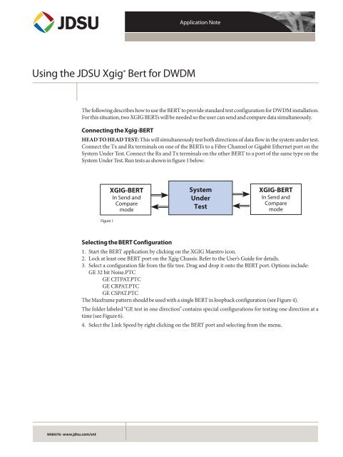
The following describes how to use the <strong>BERT</strong> to provide standard test configuration <strong>for</strong> <strong>DWDM</strong> installation.<br />
For this situation, two XGIG <strong>BERT</strong>s will be needed so the user can send and compare data simultaneously.<br />
Connecting the <strong>Xgig</strong>-<strong>BERT</strong><br />
HEAD TO HEAD TEST: This will simultaneously test both directions of data flow in the system under test.<br />
Connect the Tx and Rx terminals on one of the <strong>BERT</strong>s to a Fibre Channel or Gigabit Ethernet port on the<br />
System Under Test. Connect the Rx and Tx terminals on the other <strong>BERT</strong> to a port of the same type on the<br />
System Under Test. Run tests as shown in figure 1 below:<br />
Figure 1<br />
XGIG-<strong>BERT</strong><br />
In Send and<br />
Compare<br />
mode<br />
System<br />
Under<br />
Test<br />
XGIG-<strong>BERT</strong><br />
In Send and<br />
Compare<br />
mode<br />
Selecting the <strong>BERT</strong> Configuration<br />
1. Start the <strong>BERT</strong> application by clicking on the XGIG Maestro icon.<br />
2. Lock at least one <strong>BERT</strong> port on the <strong>Xgig</strong> Chassis. Refer to the User’s Guide <strong>for</strong> details.<br />
3. Select a configuration file from the file tree. Drag and drop it onto the <strong>BERT</strong> port. Options include:<br />
GE 32 bit Noise.PTC<br />
GE CJTPAT.PTC<br />
GE CRPAT.PTC<br />
GE CSPAT.PTC<br />
The Maxframe pattern should be used with a single <strong>BERT</strong> in loopback configuration (see Figure 4).<br />
The folder labeled “GE test in one direction” contains special configurations <strong>for</strong> testing one direction at a<br />
time (see Figure 6).<br />
4. Select the Link Speed by right clicking on the <strong>BERT</strong> port and selecting from the menu.<br />
WEBSITE: www.jdsu.com/snt
<strong>Application</strong> <strong>Note</strong>: <strong>Using</strong> the JDSU <strong>Xgig</strong>® Bert <strong>for</strong> <strong>DWDM</strong><br />
2<br />
Running the Bit Error Rate Test<br />
1. Click the Start Button to begin<br />
the test. To reset and start the<br />
BER measurement again, simply<br />
click the Stop Button and<br />
then the Start Button.<br />
2. The status display shows<br />
the status of the send and<br />
receive state machines as<br />
well as a number of other<br />
metrics.<br />
3. The Bit Error Rate shows<br />
the number of incorrect bits<br />
compared divided by the total<br />
number of bits compared<br />
since last reset.<br />
4. The Bits Mismatched number<br />
gives the count of bit<br />
errors detected by the <strong>BERT</strong>.<br />
Figure 2
<strong>Application</strong> <strong>Note</strong>: <strong>Using</strong> the JDSU <strong>Xgig</strong>® Bert <strong>for</strong> <strong>DWDM</strong><br />
3<br />
Error Insertion<br />
In order to verify that the Head to<br />
Head <strong>BERT</strong> test is connected correctly,<br />
this Bit Err button allows<br />
you to insert bit errors one at a<br />
time at one of the <strong>BERT</strong>s.<br />
By checking the bit errors detected<br />
at the other <strong>BERT</strong>, you can verify<br />
your test configuration.<br />
An Example with Errors<br />
Detected by the <strong>BERT</strong><br />
1. The Bit Error Rate is greater<br />
than the 10^-12 order of<br />
magnitude expected <strong>for</strong> a<br />
clean Fibre Channel link after<br />
68 seconds.<br />
2. The Bits Mismatched number<br />
shows the number of bits that<br />
did not match the expected<br />
pattern.<br />
Figure 3
<strong>Application</strong> <strong>Note</strong>: <strong>Using</strong> the JDSU <strong>Xgig</strong>® Bert <strong>for</strong> <strong>DWDM</strong><br />
4<br />
Additional Configurations <strong>for</strong> Testing with the XGIG-<strong>BERT</strong><br />
1. LOOPBACK TEST: Connect both the transmit (Tx) and receive (Rx) terminals on the <strong>BERT</strong> to a<br />
Fibre Channel or Gigabit Ethernet port on the System Under Test. Then loop the data path back to the<br />
<strong>BERT</strong>. The loop back can be internal or external to the System Under Test.<br />
2. LATENCY TEST: <strong>Using</strong> the same configuration as the loopback tests, this will allow you to measure<br />
the time delay through the system under test and back.<br />
XGIG-<strong>BERT</strong><br />
System<br />
Under<br />
Test<br />
Figure 4<br />
Right-click on the port column<br />
and select the desired mode of<br />
operation. Ports set to Latency<br />
mode appear on the Latency measurement<br />
tab.<br />
Select the Latency tab to run the<br />
Latency test.<br />
The Latency test function sends<br />
a data pattern repeatedly and<br />
measures the delay between<br />
transmitting and receiving each<br />
instance of the data pattern.<br />
The display shows the results in<br />
terms of Instantaneous, Average,<br />
Maximum and Minimum delay.<br />
The Latency Data Points metric<br />
shows the number of repetitions<br />
of the test.<br />
Figure 5
<strong>Application</strong> <strong>Note</strong>: <strong>Using</strong> the JDSU <strong>Xgig</strong>® Bert <strong>for</strong> <strong>DWDM</strong><br />
5<br />
3. TEST ONE DIRECTION AT A TIME: You can also run an end to end test in one direction at a time.<br />
This requires loading a send configuration in one <strong>BERT</strong> and a compare configuration in the other. Just<br />
load the configurations found a “Test In One Direction” folder.<br />
XGIG-<strong>BERT</strong><br />
In Send Only<br />
mode<br />
System<br />
Under<br />
Test<br />
XGIG-<strong>BERT</strong><br />
In Compare Only<br />
Mode<br />
XGIG-<strong>BERT</strong><br />
In Compare Only<br />
mode<br />
Figure 6<br />
System<br />
Under<br />
Test<br />
XGIG-<strong>BERT</strong><br />
In Send Only<br />
Mode<br />
Logging Options<br />
1. Right click on a port column and select the Log submenu to access Options <strong>for</strong> the Log that is created<br />
each time the <strong>BERT</strong> is stopped.<br />
2. Chose a file name template and destination folder.<br />
3. Enter values <strong>for</strong> how often to add a log entry during operation and how many log entries to make.<br />
Figure 7
<strong>Application</strong> <strong>Note</strong>: <strong>Using</strong> the JDSU <strong>Xgig</strong>® Bert <strong>for</strong> <strong>DWDM</strong><br />
6<br />
Display Options<br />
1. Right click in the port column and select LEDs to open a new window that just contains the LEDs<br />
in a larger <strong>for</strong>mat.<br />
2. Right click on the port column and select the text size submenu to choose a text size <strong>for</strong> the Parameter<br />
table.<br />
3. Right click on the port column and select Parameters to open a dialog box that allows you to<br />
choose what rows appear <strong>for</strong> all <strong>BERT</strong> ports in the Parameter table.<br />
Figure 8<br />
Test & Measurement Regional Sales<br />
NORTH AMERICA<br />
TEL: 1 888 746 6484<br />
sales-snt@jdsu.com<br />
ASIA PACIFIC<br />
apacsales-snt@jdsu.com<br />
EMEA<br />
emeasales-snt@jdsu.com<br />
WEBSITE: www.jdsu.com/snt<br />
Product specifications and descriptions in this document subject to change without notice. © 2009 JDS Uniphase Corporation 30162817 500 0909 XGIG<strong>BERT</strong><strong>DWDM</strong>.CS.SAN.TM.AE Sept 2009