E-ELT Primary Mirror Control System - ESO
E-ELT Primary Mirror Control System - ESO
E-ELT Primary Mirror Control System - ESO

Create successful ePaper yourself
Turn your PDF publications into a flip-book with our unique Google optimized e-Paper software.
!<br />
!<br />
!<br />
characteristics are simulated in more detail taking into account actuator patterns. Especially the dependency of AO<br />
rejection on M1 SVD modes and the limit of the linear response are investigated.<br />
PA C T sensor noise propagation<br />
So far noise of PACT sensors (position and acceleration) was not considered. Work is going on especially in the area of<br />
defining requirements for blind offsetting of segments for ES calibration and coherenceing. Stringent requirements on<br />
sensor accuracy might have an important impact on PACT unit price.<br />
5. I MPL E M E N T A T I O N<br />
The objective for the implementation is to provide a cost effective way to achieve the functional and performance<br />
requirements of the <strong>Primary</strong> <strong>Mirror</strong> <strong>System</strong>. The goal is to operate the M1 figure control loop with a cycle time of 1ms to<br />
enable sampling and modeling vibrations located beyond the control loop bandwidth.<br />
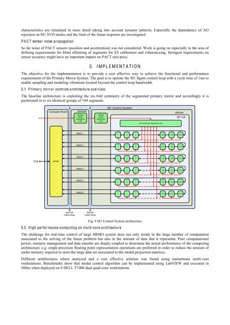
5.1 <strong>Primary</strong> mirror controls architecture overview<br />
The baseline architecture is exploiting the six-fold symmetry of the segmented primary mirror and accordingly it is<br />
partitioned in to six identical groups of 164 segments.<br />
Computer Room<br />
Azimuth<br />
Azimuth<br />
Power<br />
Distribution<br />
Unit<br />
Altitude<br />
Power<br />
Distribution<br />
Unit<br />
M1 <strong>Control</strong> <strong>System</strong><br />
M1 Cell Power Distribution Unit<br />
Altitude<br />
M1 Cell<br />
RING 1<br />
1 2 3<br />
162 163 164<br />
RING 2<br />
1 2 3<br />
162 163 164<br />
TCS<br />
M1GC<br />
RING 3<br />
1 2 3<br />
162 163 164<br />
RING 4<br />
1 2 3<br />
162 163 164<br />
RING 5<br />
1 2 3<br />
162 163 164<br />
RING 6<br />
1 2 3<br />
162 163 164<br />
Azimuth<br />
Cable Wrap<br />
Altitude<br />
Cable Wrap<br />
Fig. 9 M1 <strong>Control</strong> <strong>System</strong> architecture<br />
5.2 High performance computing on multi-core architecture<br />
The challenge for real-time control of large MIMO system does not only reside in the large number of computation<br />
associated to the solving of the linear problem but also in the amount of data that it represents. Pure computational<br />
power, memory management and data transfer are deeply coupled to determine the actual performance of the computing<br />
architecture; e.g. single-precision floating point representation operations are preferred in order to reduce the amount of<br />
cache memory required to store the large data set associated to the modal projection matrices.<br />
Different architectures where analyzed and a cost effective solution was found using mainstream multi-core<br />
workstations. Benchmarks show that modal control algorithm can be implemented using LabVIEW and executed in<br />
560us when deployed on 6 DELL T7400 dual quad-core workstations.