E-ELT Primary Mirror Control System - ESO
E-ELT Primary Mirror Control System - ESO
E-ELT Primary Mirror Control System - ESO

You also want an ePaper? Increase the reach of your titles
YUMPU automatically turns print PDFs into web optimized ePapers that Google loves.
!<br />
!<br />
!<br />
E-E L T <strong>Primary</strong> <strong>Mirror</strong> <strong>Control</strong> <strong>System</strong><br />
M. Dimmler, T. Erm, B. Bauvir, B. Sedghi, H. Bonnet, M. Müller and A. Wallander<br />
European Southern Observatory, Karl-Schwarzschild-Str. 2, 85748 Garching bei München,<br />
Germany<br />
A BST R A C T<br />
During the past year the control of the 42m segmented primary mirror of the E-<strong>ELT</strong> has been studied.<br />
This paper presents the progress in the areas of M1 figure control and control hardware implementation. The critical<br />
issue of coupling through the supporting structure has been considered in the controller design. Different control<br />
strategies have been investigated and from a tradeoff analysis modal control is proposed as a solution addressing the<br />
topics of wind rejection as well as sensor noise in the presence of cross-coupling through the supporting structure.<br />
Various implementations of the M1 <strong>Control</strong> <strong>System</strong> have been studied and a centralized architecture has been selected as<br />
baseline. This approach offers maximum flexibility for further iterations. The controller design and main parts of the<br />
control system are described.<br />
K eywords: wind rejection, edge sensor noise, figure control, modal control<br />
1. IN T R O DU C T I O N<br />
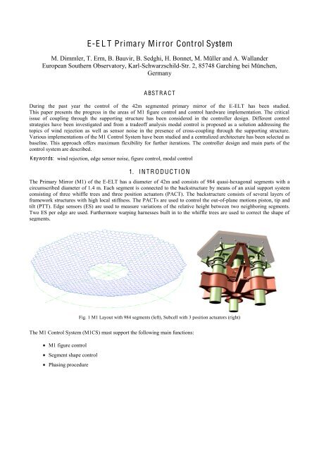
The <strong>Primary</strong> <strong>Mirror</strong> (M1) of the E-<strong>ELT</strong> has a diameter of 42m and consists of 984 quasi-hexagonal segments with a<br />
circumscribed diameter of 1.4 m. Each segment is connected to the backstructure by means of an axial support system<br />
consisting of three whiffle trees and three position actuators (PACT). The backstructure consists of several layers of<br />
framework structures with high local stiffness. The PACTs are used to control the out-of-plane motions piston, tip and<br />
tilt (PTT). Edge sensors (ES) are used to measure variations of the relative height between two neighboring segments.<br />
Two ES per edge are used. Furthermore warping harnesses built in to the whiffle trees are used to correct the shape of<br />
segments.<br />
Fig. 1 M1 Layout with 984 segments (left), Subcell with 3 position actuators (right)<br />
The M1 <strong>Control</strong> <strong>System</strong> (M1CS) must support the following main functions:<br />
M1 figure control<br />
Segment shape control<br />
Phasing procedure
!<br />
!<br />
!<br />
Failure Detection, Isolation and Recovery (FDIR)<br />
Segment integration<br />
This paper is focused on the evaluation of control strategies for the M1 figure control in the presence of disturbances and<br />
interaction between the segments introduced by the flexibility of the backstructure. The objective was to find a control<br />
strategy that delivers the required performance and can be efficiently implemented. The work has been supported by<br />
time-domain simulations using a dynamical model of the system. Another main driver for this work is to determine<br />
requirements and performance characteristics of the critical components of the M1CS.<br />
In parallel a survey of technologies and architectures has been made together with benchmarking of a potential solution<br />
for the implementation of the M1 Global <strong>Control</strong>ler (M1GC). A first baseline has been selected, which will be presented<br />
in the following chapters.<br />
2.1 <strong>Control</strong> objective<br />
2. C O N T R O L O BJE C T I V ES A ND ASSU MPT I O NS<br />
M1 figure control is responsible for maintaining the alignment of the 984 mirror segments to a level acceptable by the<br />
adaptive optics systems (telescope or post focal) in the presence of disturbances. The analysis has concentrated on<br />
finding the best control strategy that fulfills the performance requirement of 10 nm RMS wavefront after AO correction.<br />
2.2 Assumptions<br />
Various disturbances (internal and external) and noise sources are acting on the system and they are briefly described<br />
below together with assumptions used to model them. The main influences considered in the analysis are wind buffeting<br />
and ES noise.<br />
Wind disturbance<br />
The E-<strong>ELT</strong> reference wind load case on the <strong>Primary</strong> <strong>Mirror</strong> is based on a von Karman spectrum with the assumptions<br />
that the deviations from mean wind speed are small and that the wind speed field is isotropic and moved over the M1 at<br />
constant speed. The following parameters were used:<br />
Edge Sensor<br />
Wind speed Vwind= 1.7 m/s, turbulence Intensity I = 0.4 and outer scale L = 7 m.<br />
For the purpose of dynamic studies, the ES are modeled as ideal sensors (i.e. only sensitive displacement along the<br />
direction normal to the segment optical surface) with the addition of uncorrelated white noise with a level of 0.2<br />
nm/sqrt(Hz). These values are derived from the inductive edge sensor prototype developed during earlier studies.<br />
Position actuator stiffness<br />
The PACT was modeled as a pure stiffness lumped together with the stiffness of the whiffle tree. The analysis has been<br />
conducted in a way to determine the stiffness requirement rather than trying to specify the desired solution for<br />
implementation of the PACTs.<br />
Vibrations<br />
It is anticipated that the primary mirror will be exposed to narrow band vibrations in the frequency range of 10Hz to<br />
60Hz mainly from rotating machinery of the observatory. No estimates for the disturbance force amplitudes are available<br />
yet. Therefore, vibrations have not been considered in the context of this study.<br />
Telescope elevation<br />
The analysis presented in this paper is performed at a fixed elevation.<br />
Interaction matrix<br />
The <strong>Control</strong> Matrix is derived from the Interaction Matrix (IM) between the PACT and ES. Deviations from the nominal<br />
geometrical sensitivity induced by changing gravity and thermal load or by mounting errors have not been considered.
!<br />
!<br />
!<br />
A O rejection<br />
The wavefront residual after the M1 figure control system is further corrected by the adaptive optics of the telescope. We<br />
used a simple linear model for the AO system: the static fitting error of the adaptive mirror on a mode of the PACT to ES<br />
IM is proportional to the singular value of the mode. The dynamic rejection is the ideal closed loop sensitivity function<br />
of a pure integrator running at 500Hz sampling rate with a gain of 0.5. The combination of the static fitting error with the<br />
dynamic rejection law is plotted in Fig. 2.<br />
Fig. 2 AO rejection function<br />
3.1 Overview<br />
3. C O N T R O L ST R A T E G I ES<br />
From a dynamic control point of view the M1 figure control system can be represented as a MIMO system with a<br />
controller structure as shown in Fig. 3, where:<br />
G PTT is the segmented mirror to be controlled,<br />
C S is the controller matrix of the inner loop often used to adjust segment stiffness and damping based on local<br />
measurements (PACT displacement or segment acceleration). It is also used to isolate segments from vibrations<br />
of backstructure.<br />
IM is the interaction matrix from segment coordinates to edge sensor,<br />
CM is the control matrix to transform edge sensor measurements into segment coordinates,<br />
C G is the ES loop controller.<br />
The dynamical system to be controlled is represented by the transfer function matrix G PTT . For a flexible backstructure<br />
this matrix is fully populated (inter-segment coupling).
!<br />
!<br />
!<br />
For wind force rejection it is advantageous to have a high stiffness and damping on mirror level. Locally on segment<br />
level, the relative stiffness and damping between segment and backstructure can be adjusted to some extend by<br />
mechanical design or by an inner loop based on local measurements. For a flexible backstructure two main difficulties<br />
need to be addressed:<br />
The finite backstructure stiffness allows segment displacements even for locally stiff segments.<br />
Stiffening segments by an inner loop could lead to instabilities resp. performance degradation due to crosstalk.<br />
Fig. 3 M1 figure control system. Several locations of the controller matrix C G are possible: global control: C G at location (1),<br />
modal control: C G at location (2) and local control: C G at location (1) + CM modified<br />
In this paper the first point is addressed. The M1 figure control is studied with flexible backstructure neglecting any inner<br />
loop. The PACT stiffness is adjusted by parameters in the mechanical model. In a future step, details about inner loop<br />
properties and the adjustment of the inner loop are investigated. Preliminary results considering segment piston only<br />
were already presented in [1].<br />
3.2 Studied control strategies<br />
For the M1 figure control, several strategies and thus several locations for the control matrix are possible. Their main<br />
difference is in the way the ES information is used to close the loop. Three approaches were studied:<br />
Global control<br />
In global control the PTT references (u PTT ) for each segment are computed from the projection of ES signals to segment<br />
coordinates. This approach seems to be optimal to minimize ES readings. However, the closed-loop bandwidth of<br />
individual mirror modes cannot be handled easily.<br />
Modal control<br />
In modal control the controller matrix is applied in mirror mode space, defined by the Singular Value Decomposition<br />
(SVD) of the PACT to ES IM. The control bandwidth can be adjusted mode by mode to balance optimally the noise<br />
propagation and the perturbation rejection. In order to allow different controller structures for each mode independently,<br />
the ES are first projected on mirror modes and the calculated controller command is projected further on segment<br />
coordinates. Therefore, the CM is split into 2 parts and the computational load is significantly larger than for global<br />
control.<br />
Local control
!<br />
!<br />
!<br />
Local control aims also at reducing the sensitivity of the control performance to edge sensor noise with the added benefit<br />
to decrease the computational load. For this purpose the control matrix CM is approximated in a way that for each<br />
segment only measurements of segments in its proximity are used to reconstruct its position error. Three different sizes<br />
o" $se'me)* +s,-)ds/ 0ere s*2d+ed3 15 7 -)d 37 se'me)*s8 9ro:-'-*+o) o" ed'e se)sor "-+,2res +s ,+m+*ed +) r-)'e8<br />
However, cross talk between modes is increased by using only an approximation of the control matrix.<br />
3.3 Baseline for M1 figure control loop<br />
The three strategies introduced in the previous section were thoroughly studied. Modal control was selected as the<br />
baseline for the E-<strong>ELT</strong> M1 figure control for the following reasons:<br />
Flexibility<br />
In modal control, different controller dynamics can be applied for individual mirror modes or groups of mirror modes.<br />
Due to flexible backstructure, a few modes (mainly low spatial frequency modes) suffer from cross coupling (control<br />
structure interaction), whereas all other modes are practically decoupled. Using two groups of controllers avoids<br />
sacrifying bandwidths of the majority of modes for a few slow ones. This is one of the main drawbacks of global control,<br />
where the controllers are not mapped to mirror modes, but segment dynamics.<br />
ES noise propagation<br />
Some mirror modes are badly observable by ES. As a consequence ES noise has a very strong impact on these modes.<br />
The difference in noise level is more than 2 magnitudes. Noise propagation onto mirror modes is detailed in [2]. Modal<br />
control allows selecting the control bandwidth for each mirror mode independently and therefore reducing the impact of<br />
ES noise onto control performance. Local control incorporates a reduction of gains on the low spatial frequency modes<br />
by construction of the CM. However, the distribution of modal gains cannot be adjusted to optimize the performance and<br />
robustness of the system. Global control suffers from large noise propagation at low spatial frequency modes.<br />
-<br />
G PTT<br />
x PTT<br />
IM<br />
y edge<br />
noise<br />
Noise<br />
level<br />
No_edge<br />
y PTT<br />
CM 1<br />
C G<br />
CM 2<br />
Noise<br />
level<br />
No_MM<br />
=<br />
SVD: IM $ U&S&()<br />
CM = V* (S -1 U))<br />
CM = CM 1 *CM 2<br />
CM 1 = V, CM 2 = S -1 U)<br />
Fig. 4 Translation of ES noise onto noise on mirror modes. CM 2 and CM 1 are the transformation matrices from ES to SVD<br />
mirror modes and from SVD mirror modes to segment PTT, respectively.<br />
M1 kernel control<br />
Four mirror modes are unobservable by ES and several low spatial frequency modes suffer from poor observability. The<br />
non-observable modes correspond to global rigid body motions of M1 (i.e. global piston, tip and tilt) and change of<br />
radius of curvature (focus). The set of these modes need to be observed by other means, e.g. using the local PACT<br />
positions or the AO control system. Modal control allows to incorporate to the control of the M1 kernel in a<br />
straighforward manner.<br />
3.4 T radeoff of segment stiffness and ES loop bandwidth<br />
Wind rejection in the context of M1 figure control can be established at least in two ways, either by locally stiffening the<br />
segments or by high bandwidth control on edge sensors. The former approach is usually preferred for several reasons. As<br />
mentioned above practically achievable ES control loop bandwidth is limited especially for low spatial frequency modes
!<br />
!<br />
!<br />
because of noise propagation and control structure interaction. Additionally, by stiffening segments wind rejection is also<br />
improved for badly observable modes and thus telescope operations become simple.<br />
For the M1 figure control the goal is to limit the ES loop bandwidth to a few Hz and to keep the controllers as simple and<br />
robust as possible. For this purpose the necessary segment stiffness was estimated with a simplified M1 model.<br />
Each segment is modeled as a spring damper system with a relative damping of D = 0.15. Whiffle tree, PACT and<br />
framework structure stiffness are combined into one spring at each PACT location. The ES loop is assumed to have 2nd<br />
order characteristics (40 dB roll-off) with relative damping of D = 0.7 and the indicated ES loop bandwidth. All modes<br />
are controlled with identical bandwidth. The range of stiffness analyzed corresponds to the range of segment<br />
eigenfrequencies of 10-60 Hz (soft versus hard actuator). The AO characteristics of Fig. 2 are assumed.<br />
Fig. 5 shows the tradeoff between segment stiffness and ES loop bandwidth to reach the required wavefront residual of<br />
10nm after AO. As expected, it indicates that low segment stiffness induces large bandwidth requirements for the ES<br />
loop. In order to reach a residual 10 nm rms wavefront after AO with reasonable ES bandwidth, a segment stiffness of<br />
about 10N/µm is needed at each PACT location. For a whiffle tree stiffness of 17N/µm [4] and a framework structure<br />
stiffness of 100 N/µm [4] the resulting PACT stiffness has to be above 55 N/µm.<br />
Fig. 5 Tradeoff between segment stiffness and ES loop bandwidth for wind rejection.<br />
4. SI M U L A T I O NS<br />
The suitability of the baseline control strategy introduced in the previous sections was confirmed by time-domain<br />
simulations. A dynamical model of the <strong>ELT</strong> M1 was setup. Characteristic wind perturbations and an ES noise profile<br />
were generated. Modal controllers were designed and simulations were run for 60 seconds.
!<br />
!<br />
!<br />
4.1 Dynamical model of the E-E L T M1 system<br />
The M1 system is modeled in form of a finite element model . This model contains all necessary control and perturbation<br />
inputs (PACT and wind forces) and delivers segment positions in all degrees of freedom as output. The model contains<br />
about 10000 modes. It covers a frequency range of up to approximately 150 Hz. A modal damping of 0.75% is assumed.<br />
For the selected PACT stiffness of 57 N/µm the main segment eigenfrequencies of a single segment are 76 Hz in piston<br />
and 56Hz in tip and tilt.<br />
Intersegment edges are measured by ES located 5cm from segment vertices. Segment references and wind forces are<br />
expressed in PTT in order to reduce the dynamical coupling on segment level.<br />
The backstructure is rather stiff concerning high spatial frequency modes. Therefore, high spatial frequency mirror<br />
modes are well represented by the segment dynamics, almost neglecting backstructure modes. However, lower spatial<br />
frequencies mirror modes tend to excite the backstructure because of the large segment inertia involved. Fig. 6 illustrates<br />
the split of modal transfer functions in spatial frequencies.<br />
40dB<br />
Modal Transfer Functions - Low Spatial Modes<br />
40dB<br />
Modal Transfer Functions - High Spatial Frequency Modes<br />
20dB<br />
20dB<br />
0<br />
0dB<br />
-20dB<br />
-20dB<br />
-40dB<br />
-40dB<br />
0deg<br />
0deg<br />
-50deg<br />
-50deg<br />
-100deg<br />
-100deg<br />
-150deg<br />
-150deg<br />
-200deg<br />
1Hz 10Hz 100Hz<br />
-200deg<br />
1Hz 10Hz 100Hz<br />
Fig. 6 Modal transfer functions. Mechanical modes of the backstructure print through for low spatial frequencies. High<br />
spatial frequencies are dominated by segment dynamics.<br />
4.2 <strong>Control</strong>ler Design<br />
The modal controllers are designed with the objectives to provide good wind rejection, low ES noise propagation and<br />
good robustness in order to cope with the different modal transfer functions of Fig. 6 and the modal cross coupling due to<br />
flexible backstructure. The controller best suited for the listed objectives is a double integral controller with a lead-lag<br />
compensator of the form C G =K(s+b)/s 2 (s+a). The closed-loop bandwidth was adjusted to about 2Hz. Zero and pole of the<br />
lead-lag were placed at the cross-over frequency (approximatively 2Hz) and 30Hz, respectively, in order to provide<br />
enough phase margin in the region, where most of the modes are located. In addition, a mode filter in form of a simple<br />
gain scheduling was applied on the least observable modes (low spatial frequency) in order to reduce ES noise<br />
propagation into these modes. The controller has a 40dB roll-off at low frequency for wind rejection and provides a<br />
phase margin of more than 50deg for all modes. Note that for a large set of modes the closed loop bandwidth could be<br />
further increased. However, with the idealized assumptions considered so far 2Hz BW is fully sufficient.<br />
4.3 Simulation Results<br />
All simulations are run with a sampling frequency of 200Hz for duration of 60 seconds. Only the second half of the data<br />
is evaluated in order to avoid transient effects.<br />
In Fig. 7 and Fig. 8 the results of the selected strategy are given. The residual before AO is concentrated into the very<br />
low spatial frequency modes that are badly controlled with ES. After AO these errors are reduced to a few nm wavefront<br />
rms. ES noise has no visible impact to the performance. No degradation of performance and stability due to modal crosscoupling<br />
was observed.
!<br />
!<br />
!<br />
Fig. 7 PSD of the residual before AO Correction (low spatial frequency correspond to high mode numbers)<br />
Fig. 8 PSD of the residual after AO Correction
!<br />
!<br />
!<br />
4.4 Open issues and ongoing activities<br />
Even though the baseline strategy of locally stiffening the segments and applying modal control for the ES loop fulfils<br />
the requirement of wavefront error after AO, several perturbations and numerical aspects were left out in this analysis. In<br />
this chapter areas are presented, which are addressed in ongoing or future works.<br />
Influence of in-plane motions<br />
ES are sensitive to inter-segment gap and shear variations due to quasi-static telescope deformations under changing<br />
gravity (during telescope tracking) and thermal conditions. The first order effect is a quasi-static drift of the ES signal<br />
that cannot be removed by the M1 figure control system. Since some of the modes affected are difficult to reject by AO,<br />
this might have an impact on the operational strategy (recalibration of ES with phasing sensor) or compensations at ES<br />
level using a Look-Up Table (LUT) or additional sensors. Work in this area is currently ongoing. An ES model was<br />
setup and the influence of gravity and thermal errors was studied. Without compensation the magnitude of the resulting<br />
wavefront errors is similar in amplitude to the wind induced errors (approximatively 1.5 µm rms wavefront). The second<br />
order effect is a modification of the sensitivity of ES to segment PTT motions, resulting in a distortion of the IM.<br />
Sensitivity to I M numerical errors<br />
Numerical errors in the IM can cause modal crosstalk and reduce stability margins. Especially low spatial frequency<br />
modes will be affected, since they are badly observable from ES. This topic is closely related to changes of M1 geometry<br />
due to in-plane motions and mounting errors. No consolidated results are available so far, but work in this area is<br />
scheduled for second half of 2008.<br />
M1 kernel control<br />
The low spatial frequency modes suffer from bad observability with ES. At the moment several alternative strategies to<br />
control the M1 kernel, especially during telescope preset where no AO is available, are investigated (e.g. using PACT<br />
position sensors, reference segments, etc.).<br />
Stability of PA C T control loop<br />
Depending on the choice of PACT (soft or hard actuator) and the requirements concerning blind segment positioning<br />
(without ES), closing an inner loop on a local PACT sensor with sufficient stiffness at low frequencies might be very<br />
difficult because of backstructure interaction. Inner loops with sufficient bandwidth and stiffness were already simulated<br />
for E-<strong>ELT</strong> segments using a quasi-SISO design method. However, work is still going on to understand better the<br />
limitations imposed by the flexible backstructure.<br />
Vibration rejection<br />
Stiffening segments on their support in order to improve wind rejection, might allow vibrations to be transmitted from<br />
the backstructure to the segments. As mentioned earlier, especially narrow-band vibrations are expected. Since vibration<br />
frequencies are typically in the 10Hz to 60Hz frequency region (VLTI experience), they cannot be rejected by the ES<br />
loop. The E-<strong>ELT</strong> project is not yet in a state to specify the vibration levels to be expected at the level of M1 segments.<br />
Work is going on to identify critical vibration sources and their transfer function through the telescope structure. At the<br />
moment two mitigation strategies are considered to isolate segments from narrow band vibrations.<br />
Introducing notch filters allows opening the PACT loop at specific frequencies and thus lowering the backstructure-tosegment<br />
stiffness to the open loop actuator stiffness. For the vibration frequency range considered this method is only<br />
efficient for soft actuators.<br />
Vibrations could be measured by load cells or accelerometers. The measurement is used to close a local feedback loop on<br />
the PACT or in a quasi open loop scheme by imposing an oscillation in opposite phase (and tracking its frequency and<br />
phase). The former is known as Acceleration Feedback <strong>Control</strong> (AFC) and is used to improve the wind rejection of<br />
telescope axes [5]. The latter is known as Vibration Tracking (VTK) and was successfully applied to suppress vibrations<br />
for fringe tracking in VLTI [6].<br />
A O rejection<br />
So far the assumption on AO rejection comes from a crude model assuming a linear response of the AO system to M1<br />
control errors. Since it plays an important role for the estimation of post AO errors, in an ongoing activity the rejection
!<br />
!<br />
!<br />
characteristics are simulated in more detail taking into account actuator patterns. Especially the dependency of AO<br />
rejection on M1 SVD modes and the limit of the linear response are investigated.<br />
PA C T sensor noise propagation<br />
So far noise of PACT sensors (position and acceleration) was not considered. Work is going on especially in the area of<br />
defining requirements for blind offsetting of segments for ES calibration and coherenceing. Stringent requirements on<br />
sensor accuracy might have an important impact on PACT unit price.<br />
5. I MPL E M E N T A T I O N<br />
The objective for the implementation is to provide a cost effective way to achieve the functional and performance<br />
requirements of the <strong>Primary</strong> <strong>Mirror</strong> <strong>System</strong>. The goal is to operate the M1 figure control loop with a cycle time of 1ms to<br />
enable sampling and modeling vibrations located beyond the control loop bandwidth.<br />
5.1 <strong>Primary</strong> mirror controls architecture overview<br />
The baseline architecture is exploiting the six-fold symmetry of the segmented primary mirror and accordingly it is<br />
partitioned in to six identical groups of 164 segments.<br />
Computer Room<br />
Azimuth<br />
Azimuth<br />
Power<br />
Distribution<br />
Unit<br />
Altitude<br />
Power<br />
Distribution<br />
Unit<br />
M1 <strong>Control</strong> <strong>System</strong><br />
M1 Cell Power Distribution Unit<br />
Altitude<br />
M1 Cell<br />
RING 1<br />
1 2 3<br />
162 163 164<br />
RING 2<br />
1 2 3<br />
162 163 164<br />
TCS<br />
M1GC<br />
RING 3<br />
1 2 3<br />
162 163 164<br />
RING 4<br />
1 2 3<br />
162 163 164<br />
RING 5<br />
1 2 3<br />
162 163 164<br />
RING 6<br />
1 2 3<br />
162 163 164<br />
Azimuth<br />
Cable Wrap<br />
Altitude<br />
Cable Wrap<br />
Fig. 9 M1 <strong>Control</strong> <strong>System</strong> architecture<br />
5.2 High performance computing on multi-core architecture<br />
The challenge for real-time control of large MIMO system does not only reside in the large number of computation<br />
associated to the solving of the linear problem but also in the amount of data that it represents. Pure computational<br />
power, memory management and data transfer are deeply coupled to determine the actual performance of the computing<br />
architecture; e.g. single-precision floating point representation operations are preferred in order to reduce the amount of<br />
cache memory required to store the large data set associated to the modal projection matrices.<br />
Different architectures where analyzed and a cost effective solution was found using mainstream multi-core<br />
workstations. Benchmarks show that modal control algorithm can be implemented using LabVIEW and executed in<br />
560us when deployed on 6 DELL T7400 dual quad-core workstations.
!<br />
!<br />
!<br />
5.3 Communication<br />
Communication between the segment concentrators and the M1GC can be built using six identical EtherCAT rings. The<br />
data requires an address range of 5.6kBytes on each EtherCAT ring and could therefore be transmitted using four fullsize<br />
Ethernet frames.<br />
EtherCAT is a deterministic protocol using 100Mb/s Ethernet physical layer and the ring topology offers some level of<br />
redundancy and automatic failure recovery. EtherCAT would introduce a communication delay between M1GC and the<br />
segment concentrators of about 300us.<br />
5.4 Synchronization<br />
The synchronization within each of the six parts of the communications network is ensured by EtherCAT to submicrosecond<br />
accuracy. The global E-<strong>ELT</strong> Time Reference <strong>System</strong> (TRS) shall make use of the Precision Time Protocol<br />
[7] deployed on the Telescope <strong>Control</strong> Network. Synchronization between the six EtherCAT rings may be achieved by<br />
synchronizing the EtherCAT master clock of each ring to the TRS by means of an additional node connected to the<br />
telescope control network.<br />
6. C O N C L USI O N<br />
In this paper the progress in the area of E-<strong>ELT</strong> M1 figure control was summarized. Modal control with local stiffening of<br />
segments was selected as baseline for the edge sensor loop. Its main advantage compared to other strategies is its<br />
flexibility to optimize the dynamics of individual mirror modes. This fits well the needs to address different noise<br />
characteristics and sensitivities to backstructure for different mirror modes. The performance estimates were confirmed<br />
by E-<strong>ELT</strong> M1 system simulations considering ES noise and wind buffeting. The baseline strategy reached a residual<br />
below the specified value of 10 nm rms. The contribution from flexible backstructure is large before AO, but limited to<br />
slow low spatial frequency modes of the M1 kernel that can be efficiently removed by AO. For telescope preset a<br />
dedicated kernel control strategy is needed. Modal cross coupling was not a concern for the selected high M1 cell<br />
stiffness and low ES bandwidth. Lowering M1 cell stiffness will significantly reduce the performance margins.<br />
Many details were still left out for this first evaluation of the <strong>ELT</strong> M1 figure control. The open points have been<br />
identified and the planned/ongoing work was reported.<br />
A possible architecture for the implementation of the modal control baseline was presented. The necessary tests were<br />
done on a hardware demonstrator. The proposed architecture could be implemented with Commercial Off-the-shelf<br />
hardware available today.<br />
R E F E R E N C ES<br />
[1]<br />
[2]<br />
[3]<br />
[4]<br />
[5]<br />
[6]<br />
[7]<br />
Sedghi, B., Miskovic, M., Dimmler, M., "Perturbation Rejection <strong>Control</strong> Strategy for OWL," Proc. SPIE 6271, 0L1-<br />
0L12 (2006).<br />
Chanan, G., MacMartin, D. G., Nelson, J., and Mast, T., "<strong>Control</strong> and alignment of segmented-mirror telescopes:<br />
matrices, modes, and error propagation," Applied Optics Vol. 43, No.6 (2004).<br />
MacMartin, D. G. and Chanan, G., "<strong>Control</strong> of the California Extremely Large Telescope <strong>Primary</strong> <strong>Mirror</strong>," Proc.<br />
SPIE 4840, 69;80 (2002).<br />
Cavaller, L., Marrero, J., Castro, J., Ronquillo, M., Hernandez, E., "Design of the primary mirror segment support<br />
system for the E-<strong>ELT</strong>," Proc. SPIE 7012 (2008).<br />
Sedghi, B., Bauvir, B. and Dimmler, M., "Acceleration Feedback <strong>Control</strong> on an AT," Proc. SPIE 7012 (2008).<br />
Di Lieto, N., Hagenauer, P., Sahlmann, J., Vasisht, G., "Adaptive Vibration Cancellation on Large Telescopes for<br />
Stellar Interferometry," Proc. SPIE 7012 (2008).<br />
Eidson, John C., [Measurement, <strong>Control</strong> and Communication Using IEEE 1588], Springer, London (2006).