

Submarine Hull Is "Mike" - AmericanRadioHistory.Com
Submarine Hull Is "Mike" - AmericanRadioHistory.Com
Submarine Hull Is "Mike" - AmericanRadioHistory.Com

You also want an ePaper? Increase the reach of your titles
YUMPU automatically turns print PDFs into web optimized ePapers that Google loves.
526 RADIO -CRAFT :March, 1932<br />
Imp roving An AUTO RADIO<br />
In this article, the author outlines some of the problems<br />
that were encountered in the design of an automobile<br />
receiver and describes the methods used to overcome<br />
them. Just how he proceeded, makes interesting reading.<br />
T<br />
IIE trials and tribulations of the<br />
makers of automobile radio sets are<br />
many; all too often the greatest<br />
profits made from these sets have<br />
accrued to the purveyor of hair dyes to<br />
whom the harassed and grayed engineer has<br />
finally been driven.<br />
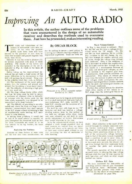
Recently it was the writer's pleasure ( ?)<br />
to become acquainted with some of these<br />
problems. The results of his labors are<br />
embodied in the description of the set illustrated<br />
in Fig. A which is the basis of<br />
this article.<br />
Before taking up the constructional details<br />
of the set itself, a brief review of the<br />
major difficulties to be ehcountered in this<br />
field will perhaps be of interest. These are,<br />
in the orderAn which they rank, as follows:<br />
(1) The inadequacy of the signal pickup<br />
system (i.e., the antenna and ground substitute)<br />
for furnishing a large signal input;<br />
(2) The difficulty of obtaining a high gain<br />
:n a very small set;<br />
(3) The close voltage limits within which<br />
the type '36 tubes must be held to secure<br />
a maximum of efficiency (this is distinctly<br />
at variance with the elauiuls made for the<br />
tube which, supposedly, was designed to be<br />
non -critical as to these factors);<br />
(4) The difficulty of providing in an automobile<br />
set, where the leads are long, a satisfactory<br />
volume- control that shall operate<br />
in the R.F. stages without introducing a loss<br />
of amplification, audio howling, R.F. oscillation<br />
or tube blocking.<br />
In solving these problems, it would also<br />
be well if we could achieve an equality of<br />
gain throughout the broadcast hand so that<br />
our little automobile set would be in no<br />
way inferior to its big brother, the home<br />
radio set.<br />
Analyzing the Problems<br />
Analysis of these factors at once rules<br />
out the first item from consideration; we<br />
r- r --- --a R2, R3 iL5<br />
By OSCAR BLOCK<br />
can do nothing to secure a good pickup in<br />
a moving car without adopting unsightly and<br />
impractical expedients. Since our little set<br />
Fig. A<br />
Photograph of the efficient automobile receiver<br />
described by Mr. Block.<br />
shall indeed have to be long on performance,<br />
in it we shall incorporate high -gain high -primary-<br />
inductance R.F. coils, carefully isolated<br />
R.F. circuits, and the maximum of regeneration<br />
possible.<br />
We shall do away with taps on our "B"<br />
batteries and shall use, instead, a voltage -<br />
dividing system; since by this method we<br />
can hold our voltages within closer limits<br />
and, once adjusted, our set shall be more<br />
nearly independent of battery fluctuations<br />
than would otherwise be the case.<br />
As to the volume- control circuit, we have<br />
adopted a really simple expedient that at<br />
once removes our control from any signal<br />
circuit and allows us to operate our tubes<br />
at their most critical point without in any<br />
way increasing the fear of oscillation or<br />
tube blocking.<br />
- Rl<br />
I. , i 12<br />
C13<br />
RI1<br />
Rld `<br />
i<br />
I<br />
'36<br />
i '36 `.. !6 C12<br />
i '37 T '38<br />
I<br />
l<br />
T<br />
=_ f fl<br />
=<br />
RS<br />
t Will<br />
CA<br />
C5 1<br />
10 L6 Ili"' lii 1<br />
il<br />
1:1 L2 R5 L3 R6<br />
EMMIEF Cll RIO<br />
!, r<br />
"/' .. %f/o s<br />
:<br />
cn - 11111<br />
'/la<br />
rÓ<br />
/' l 1 ntlD<br />
ANT GNP A `A 6 8+"<br />
RI<br />
Fig. 3<br />
The values of the resistors are such that practically no<br />
changes in plate and screen -grid voltages resIt sullen the volume is changed.<br />
<strong>Com</strong>plete diagram of the auto receiver.<br />
Novel Volume -Control<br />
In Fig. 1, this circuit is outlined. Here<br />
111, R2, R3, and R4 form a voltage- divider<br />
circuit across the "II" supply. R1, 1t3,<br />
and 114 are fixed resistors; 11.2 is variable.<br />
Any variation in 1t2 will change the current<br />
flow through the resistor network and,<br />
of course, change the voltage drop through<br />
each resistance. Thus, if the resistance of<br />
112 is decreased to reduce the amplification,<br />
the increased current flow through the circuit<br />
results in a simultaneous decrease of<br />
the plate and screen -grid voltages, as well<br />
as an increase in the negative grid bias;<br />
in combination, these provide infallible volume-<br />
control. This means of control gets<br />
away from time increase in plate and screen -<br />
grid voltages which accompanies the conventional<br />
control -grid bias -variation methods<br />
where the plate and screen -grid circuits are<br />
fed through resistances.<br />
Further, this method defeats the detection<br />
which often results at low volume in an<br />
R.F. stage when time screen -grid bias is re-<br />
Fig. 1<br />
.4 novel method of volume control; resistor R2<br />
is variable.<br />
duced. (Such detection is the result of low<br />
current through the cathode resistance causing<br />
tau -low control -grid bias.) Another<br />
advantage of this method of control is that<br />
howling, which sometimes comes as the result<br />
of the screen -grid's voltage becoming<br />
close to that of the plate, is made impossible.<br />
Such a condition is apt to occur when, as<br />
the result of decreased screen -grid current<br />
or increased plate current, the altered voltage<br />
drop through the filter resistances tends<br />
to equalize the plate and screen -grid<br />
voltages.<br />
The smooth operation of this control is<br />
no small factor in allowing the close voltage<br />
settings which the type '36 tube requires for<br />
peak operation and which no other simple<br />
method can insure.<br />
Uniform R.F. Gain<br />
We have mentioned the desirability of<br />
providing uniform over -all gain throughout<br />
the broadcast hand. Mechanical means<br />
through movable primary coils could he<br />
used but for the ideals of compactness and<br />
(Continued on page 556)


