

Submarine Hull Is "Mike" - AmericanRadioHistory.Com
Submarine Hull Is "Mike" - AmericanRadioHistory.Com
Submarine Hull Is "Mike" - AmericanRadioHistory.Com

You also want an ePaper? Increase the reach of your titles
YUMPU automatically turns print PDFs into web optimized ePapers that Google loves.
lo<br />
552<br />
1932 PRICE GUIDE<br />
Radio Supplies- Tubes -Sets<br />
Every item you require in your business is<br />
in this book, from the finest high grade<br />
mike to the smallest screw.<br />
GUARANTEED QUALITY GOODS<br />
Prices Lowest Erer Quoted<br />
Fresh new dependable Merchandise at<br />
Bargain Prices!<br />
Leading Manufacturers Lines <strong>Com</strong>plete<br />
Send For Your Copy Now!<br />
SAMPLE BUYS FROM THIS BOOK<br />
$14.65 $1.98 69c<br />
4Tube Replacement 500V -8Mf<br />
Receiver Transformer Dry Cond.<br />
and Three Thousand Other Bargains<br />
HEADQUARTERS<br />
for SERVICE MEN'S SUPPLIES<br />
RaJolek Co.,<br />
103<br />
Canal Station<br />
Chicago, Ill.<br />
Please send me without obligation<br />
your Service Man's Supply Book.<br />
Name -<br />
Address --<br />
City.<br />
State<br />
Electrolytic<br />
Condensers<br />
Conservative voltage ratings,<br />
fastest reforming, lowest leakage<br />
factor, minimum noise,<br />
exceptionally low power factor,<br />
most effective filtering.<br />
longest service life - these<br />
features characterize Dubilier<br />
Electrolytic Condensers.<br />
RADIO -CRAFT March, 1932<br />
"SUB" HULL IS "MIKE"- REPRODUCER<br />
hull of the submarine but should he separated<br />
by a thin wall of water. For this<br />
reason, the diaphragms are clamped on the<br />
reproducer by capped screws which project<br />
one -quarter inch from the surface and not<br />
by flat -headed screws. An external view<br />
of the re- producer is shown in Fig. I) and<br />
an internal view showing all component<br />
parts, appears in Fig. E.<br />
Description of Apparatus<br />
(Continued from page 521)<br />
The apparatus consists of a model MG<br />
underwater reproducer, including the type<br />
SE 3489 under -sea reproducer and SE 3488<br />
power amplifier with auxiliary batteries, announcing<br />
microphone, telephones and cable<br />
equipment. The reproducer is essentially<br />
an electrodynamic speaker of novel design,<br />
employing the use of two parallel diaphragms<br />
connected by a tube as an armature.<br />
These diaphragms are only .070-in.<br />
thick and are accurately machined front<br />
bronze metal to the end that they be noncorrosive<br />
and non -magnetic. The other component<br />
parts of the magnetic speaker are<br />
the iron magnetic casing or pole pieces,<br />
D.C. field coil and core with the A.C. coil,<br />
or speaking coil, wound thereon.<br />
The design and arrangement of the parts<br />
are such as to withstand external hydrostatic<br />
pressures up to 150 pounds per square<br />
inch. This arrangement of the parts necessitates<br />
much care in the machining of them<br />
and their assembly. The machined dimensions<br />
of the depths of the brass casting and<br />
the diaphragms must equal the length of<br />
the armature tube. So, if the rubber gaskets<br />
maintaining water -tightness are too<br />
thick, preventing the parts coning together,<br />
there will be lost motion between the armature<br />
tube and the diaphragm. ii. .1uch care<br />
is given this feature so the operation of the<br />
s )taker will not stiffer interference by<br />
grounds or short circuits that would be<br />
cunset' by salt water in the reproducer.<br />
The type SE :1488 transmitter-receiver,<br />
the diagram of which is shown in Fig. 1,<br />
includes in its essentials one two -stage receiver-<br />
amplifier and one four -stage power<br />
amplifier having a push -pull output stage.<br />
'l'he large 48 -volt storage battery supplies<br />
a fi -volt supply to the filaments of the SE<br />
4374 (l'X 201A) tubes and the talking microphone,<br />
and a 10 -volt supply to the<br />
filaments of the l'X 250 and SF, 2566 (CX<br />
210) tubes. 'l'he remaining group of batteries<br />
supplies 38 volts to the motor end<br />
of a dynamotor through the relay contacts.<br />
Fig. D<br />
Close -op view of the magnetic unit.<br />
The coils of the SE 1914 relays are energized<br />
front 20 volts through the "press -totalk"<br />
switch in the handle of the microphone.<br />
'l'he 90 -volt supply for the plaste voltage<br />
to the type SE 4:374 (l'X 201:1) tubes is<br />
obtained front self- contained type SP. :35:35<br />
"11" batteries. A 90 -volt negative grid bias<br />
for the 1-X 250 and :35-volt grid bias to the<br />
SE 2566 (l'X 2111) tubes is supplied from<br />
"Ii" batteries used as "C"<br />
type SF. :1535<br />
batteries. A negative 4//-. -volt bias for the<br />
type SE 4:374 (l'X 201:\) tubes is obtained<br />
from a small 41ß_- colt "C" battery.<br />
e<br />
Available in upright or<br />
inverted aluminum cans,<br />
and in cardboard containers<br />
with lug or wire<br />
lead terminals. In single<br />
and multiple section<br />
units, and in capacities<br />
up to 20 mfd., for high<br />
and for low D. C. voltages.<br />
Write for Catalog 121<br />
describing Dubilier electrolytic<br />
condensers as<br />
well as paper, mica and<br />
other dielectric condensers<br />
for all purpose,<br />
Dubilier<br />
Condenser Corporation<br />
New York City<br />
4377 Bronx Blvd.<br />
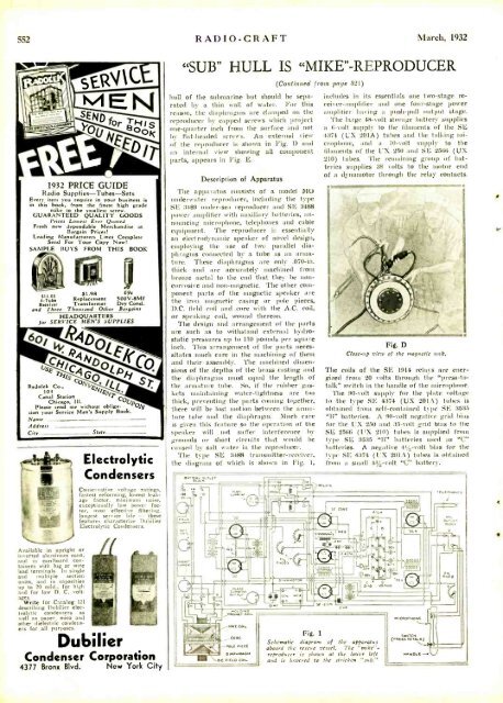
Fig. 1<br />
Schematic diagram of the apparatus<br />
aboard the rescue vessel. The "mike" -<br />
reproducer is shown at the lower left<br />
and is lowered to the stricken "sub."<br />
NaeR0RN0N<br />
SwIrCN<br />
(eeFSerae relN)<br />
NeN x e-<br />
l;!<br />
i


