

Submarine Hull Is "Mike" - AmericanRadioHistory.Com
Submarine Hull Is "Mike" - AmericanRadioHistory.Com
Submarine Hull Is "Mike" - AmericanRadioHistory.Com

You also want an ePaper? Increase the reach of your titles
YUMPU automatically turns print PDFs into web optimized ePapers that Google loves.
548 RADIO-CRAFT March, 1932<br />
Radio -Craft's Information Bureau<br />
SPECIAL NOTICE TO CORRESPONDENTS: Ask as many questions as you like, but<br />
please observe these rules:<br />
Furnish sufficient information, and draw a careful diagram when needed, to explain your meaning; use<br />
only one side of the paper. List each question.<br />
%hose questions which are found to represent the greatest general interest will be published here, to the<br />
extent that space permits. At least five weeks must elapse between the receipt of o question and the<br />
appearance of its answer here.<br />
Replies, magacines, etc., cannot be sent C. O. D.<br />
Inquiries can be answered by mail only when accompanied by 25 cents (stamps) for each separate question.<br />
Other inquiries should be marked "For Publication," to avoid misunderstanding.<br />
j<br />
LINCOLN MODEL D.C. SW 10<br />
ALL -WAVE RECEIVER<br />
(149) Mr. Robert Smilovitz. Carnegie, Pa.<br />
(Q.1) In the January, 1932 issue of RADto-<br />
CRAPT, on pg. 417, was shown the schematic circuit<br />
of the Lincoln DeLuxe SW 32 All -Wave Receiver,<br />
In the article describing this circuit, mention was<br />
made of a battery model. Please show the achemask<br />
circuit of this receiver.<br />
(A.I) In Fig. Q.149 is illustrated the schematic<br />
circuit referred to, the Lincoln Model U.C. SW 10<br />
All -Wave Receiver.<br />
All available parts values appear in the diagram.<br />
In general, the circuit is the same as used in the<br />
A.C. model. except for the changes necessary for<br />
the utilization of battery power for the ".1," "B,"<br />
and "C" circuits.<br />
INSTALLING AUTO -RADIO<br />
REMOTE CONTROLS<br />
(150) Mr. James Peterson, Bronx, N. Y.<br />
(Q.1) Please describe in detail the manner in<br />
which Carter auto.radio remote control units are<br />
mounted in the car and adjusted to the radio set.<br />
As indicated in the illustration (reproduced here<br />
as Fig. Q.150Á). there are 10 main parts to the<br />
assembly; and just how they can be adapted to various<br />
installations is not at all clear.<br />
(A.I) The parts referred to in the illustration<br />
hear the following classifications: (A), control<br />
head with control cable and electric cable attached;<br />
(Il), two semi- circular clamps for securing the head<br />
to the steering post (one grounding set -screw in<br />
each); (C), four 8 -32 x 15 -ins. round -head<br />
screws (to attach clamp to control head); (U), four<br />
No. 8 internal tooth lock -washers (for clamp<br />
screws); (E), two leather spacers; (F), one brass<br />
hexagon cable -chuck (consisting of three parts);<br />
((:). one condenser pulley (with two set -screws in<br />
hub and cable clamping screw and washer); (Il),<br />
one spiral spring; (I), one centering ring; (J),<br />
two keys for lock.<br />
In mentioning the condenser pulley (1. the Centering<br />
ring encircles the condenser shaft with the<br />
lugs projecting through the condenser end plate.<br />
These holes should be ' .in, in diameter and 75 -in.<br />
between centers. They are provided on some con-<br />
densers, but will have to be drilled in. some others.<br />
When the ring is in place, bend the lugs over on<br />
the inside of the end plate.<br />
The inside turn of the spiral spring is provided<br />
with an offset bend. This is locked in. the slot in<br />
the centering ring and the loop on the outside turn<br />
is placed on one of the twelve projecting pins on<br />
the condenser pulley. The spring is then wound<br />
by turning the condenser pulley on the shaft. Usually<br />
about one turn provides sufficient tension. The<br />
pulley set- screws are then tightened on the shaft,<br />
being careful that some clearance is allowed between<br />
the projecting pins and the condenser end plate to<br />
prevent binding. When the proper tension has been<br />
determined, it may be that the cable clamping screw<br />
on the pulley is not in the proper position for operation.<br />
The same tension can be maintained and<br />
the position of the clamping screw corrected by<br />
moving the loop on the outside turn of the spiral<br />
spring to a different pin on the pulley. A minimum<br />
of U -in. clear space and 9 /16-in. condenser<br />
shaft extension is required at one end of the condenser<br />
for mounting the condenser pulley.<br />
The cable chuck, which is in three parts, can be<br />
mounted in the receiver housing or on a bracket<br />
secured to the condenser or chassis. It mounts in<br />
a a -in. hole, the large jam nut fitting on the tapered<br />
end and the lock nut on the short end. This<br />
chuck may be located any distance from the condenser<br />
pulley but should be in line with the center<br />
of the groove in the pulley.<br />
Now. turn the selector knob as far as it will go<br />
in a clockwise direction, to begin the procedure of<br />
mounting the control unit. This draws the cable<br />
into the tubular housing and protects it from injury<br />
at the free end. Keep it in this position during installation.<br />
The control head A is mounted on the<br />
steering post with the knobs projecting toward the<br />
right -hand side. The proper distance below the<br />
steering wheel can be determined by trial. If the<br />
steering post is 1 % ins. in diameter. use the leather<br />
spacers E. If I)4 ins., split the spacers or wrap<br />
the post with about 1 /16-in. of friction tape, under<br />
the brackets. If the post is 13,1 ins.. spacers are<br />
not required. Use the lock washers U unaer the<br />
heads of the clamp screws C for securing the clamps<br />
B to the head.<br />
Run the control cable in as straight a line as<br />
possible, avoiding any short bends.<br />
It should be understood that while the cable is<br />
flexible and will function smoothly even though it<br />
does not run in a straight line, nevertheless it must<br />
not be abused. Kinks should be avoided as they<br />
impair the operation of the set. This department<br />
has received a number of letters from people who<br />
maintain that the tuning cable on their auto set<br />
does not function properly. Upon investigation it<br />
was found that in their hurry to install the receiver.<br />
no consideration was given to the placement of the<br />
parts, which resulted in mechanical breakdowns.<br />
-A-<br />
s: w tuSC<br />
.,j<br />
RED (1<br />
C) i.:,°n NW.. stRY.If<br />
-ë<br />
7<br />
¡t<br />
-C- RED AlV<br />
,<br />
s[l<br />
(,<br />
C)<br />
-B-<br />
.>,ö<br />
R =<br />
In<br />
.v uL'1<br />
_s"wt =<br />
e<br />
-- aö<br />
Iq<br />
1Y3J<br />
Fig. Q150B<br />
Several circuits in which the remote tuning<br />
cable may be used. The correct one depends<br />
spots the particular cable on hand.<br />
The next step is to loosen the large jam nut on<br />
the cable chuck. Insert the free end of the cable<br />
and its tubular housing. The weatherproof braid<br />
at this end is removed to expose the metal spring;<br />
here the housing with the weatherproof covering<br />
will not enter the chuck. If it is necessary to insert<br />
the housing so that it extends farther through<br />
the chuck. remove the covering for that distance and<br />
tighten the jam nut. Ile sure that the selector<br />
knob on the control head is still turned to the<br />
stop ill the clockwise direction. Turn the condensers<br />
to the extreme position (against the returning<br />
action of the spring and toward the free<br />
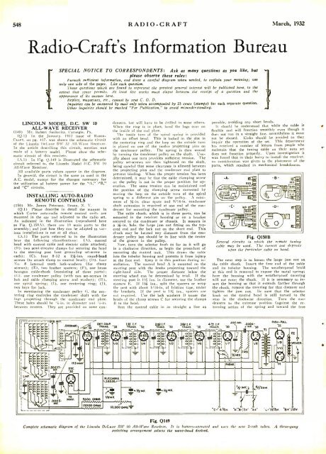
Fig. 0149<br />
<strong>Com</strong>plete schematic diagram of the Lincoln DeLuxe Sit' 10 .411-Wave Receiver. It is battery- operated and uses the neso 2 -volt tubes. .4 three -gang<br />
:.,itching arrangement selects the wave -band desired.


