

Submarine Hull Is "Mike" - AmericanRadioHistory.Com
Submarine Hull Is "Mike" - AmericanRadioHistory.Com
Submarine Hull Is "Mike" - AmericanRadioHistory.Com

Create successful ePaper yourself
Turn your PDF publications into a flip-book with our unique Google optimized e-Paper software.
536 RADIO-CRAFT Vlarch, 1932<br />
Operating Notes<br />
The Analysis of Radio Receiver Symptoms<br />
DURING the past season, a great<br />
number of new radio receivers made<br />
their appearance. Almost every<br />
reputable manufacturer released at<br />
least one receiver employing the superheterodyne<br />
circuit, variable -mu and pentode<br />
tubes, tone control and automatic volume -<br />
control. Although these advanced features<br />
resulted in far better radio receivers, their<br />
use brought their attendant difficulties. On<br />
the other hand, many problems have arisen<br />
because of certain common failures of component<br />
parts.<br />
Fig. 1<br />
Socket arrangement of the Colonial 47 receiver.<br />
Three variable -ma tubes are used.<br />
Colonial Model 47<br />
In the Colonial Model 41, a superheterodyne<br />
receiver, the condition of unstable operation<br />
accompvticd with the complaint<br />
of pour tone at moderate volume has been<br />
found to be caused i,v the misplacement of<br />
the screen -grid tubes. 'three variable-ant<br />
type ':35 tubes are used in this receiver as<br />
well as one type '2+ as a second- detector.<br />
When a '35 is placed in the Seel Mil-detect<br />
stage, the above complaint will ensue. This<br />
tube will not function properly as a detector<br />
in it T.R.F. receiver, or seconddetector<br />
in rt superheterodyne, bee:lose of<br />
its electrical characteristics. 'I'he socket<br />
arrangement of the Colonial IT is illustrated<br />
in Fig. 1.<br />
Reception on this model is often marred<br />
by hunt, slight in some cruses, and in others<br />
quite disturbing. This condition is not<br />
caused by any defective part. Its presence<br />
can only be attributable to poor mechanical<br />
design, resulting in interstage coupling.<br />
Stromberg- Carlson Models 25, 26<br />
Some time ago, an interesting problem<br />
was presented by a Strotnluerg- Carlson Model<br />
25, 26 receiver. The complaint was "intermittent<br />
reception." After the set had been<br />
in use for a few minutes, it would suddenly<br />
go "dead." When the line switch wag<br />
snapped off and then on again, recept'<br />
would be resumed. the other Weil the<br />
By BERTRAM M. FREED<br />
receiver would stop and start up again<br />
without anyone having disturbed it in the<br />
least. A thorough cheek dtselused a lack of<br />
plate voltage on the screen -grid detector.<br />
The chassis was taken down in an attempt<br />
to locate the trouble.<br />
The primary of the input push -pull audio<br />
transformer was tested but this winding<br />
proved O. K. (Besides, if the primary had<br />
been open, a voltage reading would have<br />
been obtained at the detector plate, because<br />
of the 2.50,000 -ohms carbon resistor shunted<br />
across the winding as a loading device, since<br />
the plate impedance of the screen -grid tube<br />
as a detector is high.) 'the 40,000 -ohm car-<br />
bon resistor used to reduce the high voltage<br />
to that required by the detector, was suspected,<br />
but this also proved correct when<br />
it resistance measurement was made.<br />
A "short" test made from detector plate<br />
to chassis pruduccd only a very high resistance<br />
effect, app,trentl pointing to no trouble<br />
a n this point. With the receiver turned on,<br />
oltage measurements were sonde front the<br />
II+" side of the primary. This showed 20<br />
olts, but the reading obtained from the<br />
1 igh "I1 +" terminal of the voltage divider,<br />
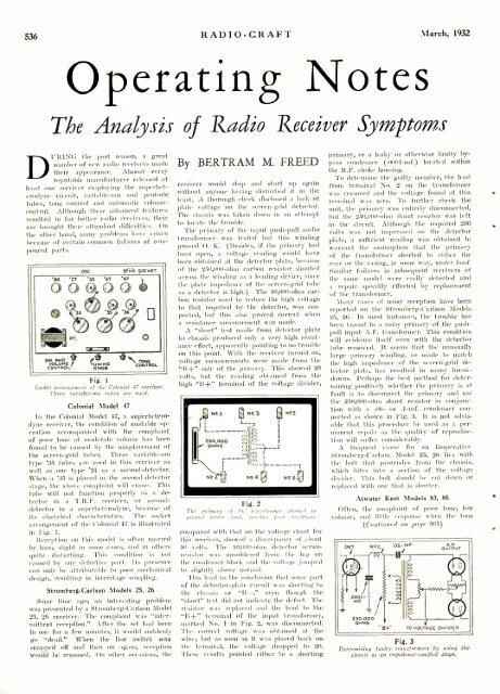
Fig. 2<br />
The primary of the transformer started to<br />
ground under (oast, causing por reception.<br />
compared with that on the voltage chart for<br />
this receiver, showed a discrepancy of about<br />
40 cults. The 10,111111 -ohm detector series -<br />
resistor was unsoldered from<br />
the lug un<br />
the condenser block and the voltage .jumped<br />
to slightly above normal.<br />
This kill to the conclusion that sonie part<br />
of the detector -plate circuit was .shorting to<br />
the chassis or "II - -;' even though the<br />
"short" test did not indicate the defect. The<br />
resistor ens replaced soul the howl tu the<br />
"11ß-" terminal of the input transformer,<br />
marked NO. 1 in Fig. 2. was disconnected.<br />
The correct voltage was obtained at the<br />
wire; but as soon as it was placed back on<br />
the terminal. the voltage dropped to 20.<br />
These results l ' ted either to st shorting<br />
primary, or it leaky or otherwise faulty bypass<br />
condenser (.01)111-inf.) located within<br />
the lt.F. choke housing.<br />
To determine the guilty member, the lead<br />
from terminal No. 2 on the transformer<br />
was removed and the voltage found at this<br />
terutinnl was zero. 'l'o further check the<br />
unit, the primary was entirely disconnected,<br />
but the 2511,01 to -uhnt shunt resistor was left<br />
in the circuit. Although the required 200<br />
volts was not impressed on the detector<br />
plate, a sufficient reading was obtained to<br />
warrant the assumption that the primary<br />
of the transformer shorted to either the<br />
core or the erasing, in some way, under load.<br />
Similar fail wt's in subsequent receivers of<br />
the saute utodcl were easily detected and<br />
a repair speedily effected by replacement<br />
of the transformer.<br />
Many erases of noisy reception have been<br />
reported on the Stromberg- Carlson Models<br />
25, 26. In most instances, the trouble has<br />
been traced to a noisy primary of the push -<br />
pull input A.F. transformer. This condition<br />
will evidence itself even with the detector<br />
tube removed. It seems that the unusually<br />
large primary winding, so made to match<br />
the high impedance of the screen -grid detector<br />
plate. has resulted in utany breakdowns.<br />
Perhaps the hest method for determining<br />
positively whether the primary is at<br />
fault is to disconnect the primary and use<br />
the 250,000 -ulnt shunt resistor in conjtinetiun<br />
with a .06- or .1 -ntf. condenser connected<br />
as shown in Fig. 3. It is not advisable<br />
that this procedure be used as a per -<br />
manent repair as the quality of reproduction<br />
will suffer considerably.<br />
:\ frequent cause fur an inoperative<br />
Stromtberg- Carlson Model 25, 26 lies with<br />
the bolt that protrudes front the chassis,<br />
which bites into a section of the voltage<br />
divider. 'Phis bolt should be cud dozen or<br />
replaced with one that is shorter.<br />
Atwater Kent Models 83, 85<br />
Often, the complaint of pour tone, low<br />
volume, and little response when the tone<br />
(Continued ant page 565)<br />
Fig. 3<br />
Determining faulty transfmmers by using the.<br />
circuit as an impedance -coupled stage.


