pre-lab preparation sheet for lab 4—batteries, bulbs, and current
pre-lab preparation sheet for lab 4—batteries, bulbs, and current
pre-lab preparation sheet for lab 4—batteries, bulbs, and current

You also want an ePaper? Increase the reach of your titles
YUMPU automatically turns print PDFs into web optimized ePapers that Google loves.
Name_____________________________________ Date_______________________<br />
PRE-LAB PREPARATION SHEET FOR LAB 4—BATTERIES, BULBS,<br />
Directions:<br />
AND CURRENT<br />
(Due at the beginning of <strong>lab</strong>)<br />
Read over Lab 4 <strong>and</strong> then answer the following questions about the procedures.<br />
1. Explain why in Activity 1-1 the angle irons will be charged in several different<br />
ways.<br />
2. Sketch below one arrangement of the battery, bulb, <strong>and</strong> wire (other than the one in<br />
Figure 4-3) that you will study in Activity 1-2.<br />
3. At this time, which of the models shown in Figure 4-6 <strong>for</strong> how <strong>current</strong> flows in a<br />
circuit do you favor? Why?<br />
4. Describe briefly how you will test the models <strong>for</strong> <strong>current</strong>. What device will you<br />
use to measure <strong>current</strong>?<br />
5. Sketch the symbols <strong>for</strong> a battery <strong>and</strong> <strong>for</strong> a light bulb below.<br />
Lab 04 – Batteries <strong>and</strong> Current
Lab 04 – Batteries <strong>and</strong> Current
Name_________________________ Date____________ Partners________________<br />
LAB 4: BATTERIES, BULBS, AND CURRENT*<br />
You cannot teach a man anything; you can only help him to find it within<br />
himself.<br />
OBJECTIVES<br />
—Galileo<br />
• To underst<strong>and</strong> how a potential difference (voltage) can cause an electric <strong>current</strong> to flow<br />
in a conductor.<br />
• To learn to design <strong>and</strong> construct simple circuits using batteries, <strong>bulbs</strong>, wires, <strong>and</strong><br />
switches.<br />
• To learn how to draw circuit diagrams using st<strong>and</strong>ard circuit symbols.<br />
• To underst<strong>and</strong> the measurement of <strong>current</strong> <strong>and</strong> voltage using microcomputer-based<br />
sensors.<br />
• To underst<strong>and</strong> what <strong>current</strong>s will flow in various parts of simple DC circuits, <strong>and</strong> why.<br />
OVERVIEW<br />
In the following <strong>lab</strong>s, you are going to discover <strong>and</strong> extend theories about electric charge<br />
<strong>and</strong> potential difference (voltage), <strong>and</strong> apply them to electric circuits. What you learn will<br />
be one of the most practical parts of the whole physics course, since electric circuits <strong>for</strong>m<br />
the backbone of modern technology. Without an underst<strong>and</strong>ing of electric circuits we<br />
wouldn’t have lights, air conditioners, automobiles, telephones, TV sets, dishwashers,<br />
computers, or photocopying machines.<br />
A battery is a device that generates an electric potential difference (voltage) from<br />
other <strong>for</strong>ms of energy. The type of batteries you will use in these <strong>lab</strong>s are known as<br />
chemical batteries because they convert internal chemical energy (energy stored in<br />
chemical bonds) into electrical energy.<br />
As a result of a potential difference, electric charge is repelled from one terminal of<br />
the battery <strong>and</strong> attracted to the other. However, no charge can flow out of a battery unless<br />
Lab 04 – Batteries <strong>and</strong> Current
there is a conducting material connected between its terminals. If this conductor happens<br />
to be the filament in a small light bulb, the flow of charge will cause the light bulb to<br />
glow.<br />
*Some activities in this <strong>lab</strong> have been adapted from those designed by the Physics Education Group at the<br />
University of Washington, included in Workshop Physics, Module 4.<br />
In this <strong>lab</strong> you are going to explore how charge flows in wires <strong>and</strong> <strong>bulbs</strong> when energy<br />
is provided by a battery. You will be asked to develop <strong>and</strong> explain some models that<br />
<strong>pre</strong>dict how the charge flows. You will also be asked to devise ways to test your models<br />
using computer-based <strong>current</strong> <strong>and</strong> voltage sensors that measure the rate of flow of electric<br />
charge (<strong>current</strong>) <strong>and</strong> the potential difference (voltage), respectively, <strong>and</strong> display these<br />
quantities on a computer screen using data collection <strong>and</strong> analysis software.<br />
INVESTIGATION 1: MODELS THAT DESCRIBE<br />
CURRENT FLOW<br />
What is electric <strong>current</strong>? As you have seen in Lab 1, the <strong>for</strong>ces between objects that are<br />
rubbed in particular ways can be attributed to a property of matter known as charge (static<br />
electricity). Most textbooks assert that the electric <strong>current</strong>s through the wires connected to<br />
a battery are charges in motion. How do we know this? Perhaps <strong>current</strong> is something<br />
else—another phenomenon.<br />
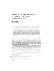
This question received a great deal of attention from Michael Faraday, a famous earlynineteenth-century<br />
scientist. Faraday studied the effects of electricity from animals<br />
including electric eels summarized his results in a table like the one shown in Figure 4-1,<br />
<strong>and</strong> concluded that ―electricity, whatever may be its source, is identical in its nature.‖ 1<br />
Physiological effect<br />
Magnetic deflection<br />
Magnets made<br />
Spark<br />
Heating power<br />
True chemical action<br />
Attraction <strong>and</strong> repulsion<br />
Discharge by hot air<br />
1. Voltaic electricity X X X X X X X X<br />
2. Common electricity X X X X X X X X<br />
3. Magneto-electricity X X X X X X X<br />
4. Thermo-electricity X X + + + +<br />
5. Animal electricity X X X + + X<br />
Figure 4-1: Faraday’s table. The X’s denote results obtained by Faraday <strong>and</strong> the +’s denote positive results<br />
found later by other investigators.<br />
Lab 04 – Batteries <strong>and</strong> Current
The purpose of the first activity is to compare carriers of the <strong>current</strong> produced by a battery<br />
to the static charges deposited by rubbing materials together. You will observe a<br />
demonstration using the following materials:<br />
• 2 metal angle irons (approx. 15 cm long)<br />
• foil-covered Styrofoam ball on a string (2.5 cm diameter)<br />
• 300-V battery pack or power supply<br />
• hard rubber (plastic or Teflon © ) rod <strong>and</strong> fur<br />
• glass or acrylic rod <strong>and</strong> polyester, felt or silk cloth<br />
• electroscope<br />
• alligator clip leads<br />
• Wimshurst or Van de Graaff generator (optional)<br />
1 Faraday, M. ―Identity of Electrocutes Derived from Different Sources,‖ in Experimental Researches in<br />
Electricity, Vol. I, Taylor <strong>and</strong> Francis, London. (Reprinted by Dover Publications, New York, 1965, p. 76).<br />
Activity 1-1: Comparing Stuff from a Battery to the Rubbing<br />
Stuff<br />
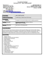
1. The angle irons, ball, <strong>and</strong> electroscope will be set up as shown in Figure 4-2.<br />
Figure 4-2: Apparatus <strong>for</strong> detecting charge.<br />
2. The metal angle irons will be charged in two or more of the following ways:<br />
a. Electrostatic Charging by Rubbing. Stroke one plate with a rubber rod that has been<br />
rubbed with the fur. Repeat this several times. Stroke the other plate with the glass<br />
rod that has been rubbed with the polyester cloth.<br />
b. Charging with a Battery. Connect a wire from the negative terminal of the power<br />
supply to one of the angle irons. At the same time connect a wire from the positive<br />
terminal to the other plate.<br />
Lab 04 – Batteries <strong>and</strong> Current
c. Charging with a Wimshurst or Van de Graaff Generator. Connect a wire from one<br />
of the two terminals of the generator to one angle iron, <strong>and</strong> a wire from the other<br />
terminal to the other angle iron.<br />
3. Observe whether the different charging methods have different effects on the<br />
electroscope <strong>and</strong> on the ball when it is dangled between the two metal angle irons.<br />
4. The metal angle irons will then be separated so the gap between them is just barely<br />
bigger than the diameter of the foil covered ball, <strong>and</strong> the ball will be carefully placed<br />
between them. You should observe something unusual.<br />
Question 1-1: What happened to the electroscope when the angle irons were charged<br />
using the familiar rubbing method described in (a) above? Why?<br />
Question 1-2: What happened when the ball was placed between the angle irons? Use<br />
your underst<strong>and</strong>ing of the attraction <strong>and</strong> repulsion of different types of charges to explain<br />
why this unusual phenomenon happened.<br />
Question 1-3: Describe what happened when the power supply charged the angle irons.<br />
What differences (if any) did you observe in the response of the electroscope <strong>and</strong> the ball<br />
to the charges on the angle irons?<br />
Question 1-4: If the Wimshurst or Van de Graaff generator was also used, describe what<br />
happened. Did you observe any difference in the response of the ball to the charges on the<br />
angle irons? How about the response of the electroscope?<br />
Lab 04 – Batteries <strong>and</strong> Current
Question 1-5: Do the charges generated by rubbing <strong>and</strong> those from the power supply<br />
cause different effects? If so, describe them. Do the charges generated in these two ways<br />
seem different?<br />
The rate of electric charge flow is called electric <strong>current</strong>. If charge q flows through the<br />
cross section of a conductor in time t, then the average <strong>current</strong> can be ex<strong>pre</strong>ssed<br />
mathematically by the relationship<br />
i<br />
q<br />
t<br />
Instantaneous <strong>current</strong> is defined as the charge per unit time passing through a particular<br />
part of a circuit at an instant in time. It is defined by using the limit:<br />
as<br />
q<br />
i limit<br />
t<br />
t 0<br />
The unit of <strong>current</strong>, called the ampere (A), re<strong>pre</strong>sents the flow of one coulomb of<br />
charge in a time of one second. Another common unit is the milliampere (mA) (1 ampere<br />
= 1000 milliamperes). Usually people just refer to <strong>current</strong> as ―amps‖ or ―milliamps.‖<br />
In the next activity, you can begin exploring electric <strong>current</strong> by lighting a bulb with a<br />
battery. You will need the following:<br />
• flashlight bulb (#14)<br />
• flashlight battery (1.5-V D cell, alkaline <strong>and</strong> very fresh)<br />
• wire (6 inches or more in length)<br />
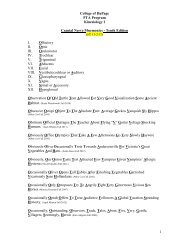
Activity 1-2: Arrangements that Cause a Bulb to Light<br />
Use the materials listed above to find some arrangements in which the bulb lights <strong>and</strong><br />
some in which it does not light. For instance, try the arrangement shown in Figure 4-3.<br />
Figure 4-3: A wiring configuration that might cause a battery to light a bulb.<br />
Lab 04 – Batteries <strong>and</strong> Current
Question 1-6: Sketch two arrangements <strong>for</strong> which the bulb lights.<br />
Question 1-7: Sketch two arrangements <strong>for</strong> which the bulb doesn’t light.<br />
Question 1-8: Describe as fully as possible the conditions needed <strong>for</strong> the bulb to light.<br />
Explain why the bulb fails to light in the arrangements drawn in answer to Question 1-7.<br />
Next you will explore materials connected between a battery <strong>and</strong> a bulb allow the bulb to<br />
light. Since it seems that something flows from the battery to the bulb, we refer to<br />
materials that allow this flow as conductors <strong>and</strong> those that don’t as nonconductors or<br />
insulators.<br />
You will need<br />
• common objects (paper clips, pencils, coins, rubber b<strong>and</strong>s, fingers, paper, keys, etc.)<br />
Activity 1-3: Other Materials Between the Battery <strong>and</strong> Bulb<br />
Set up the single wire, battery, <strong>and</strong> bulb so that the bulb lights, e.g., one of the<br />
arrangements drawn in your answer to Question 1-6. Then, with the help of your partner,<br />
stick a variety of the common objects avai<strong>lab</strong>le between the battery <strong>and</strong> the bulb.<br />
Question 1-9: List some materials that allow the bulb to light.<br />
Question 1-10: List some materials that <strong>pre</strong>vent the bulb from lighting.<br />
Lab 04 – Batteries <strong>and</strong> Current
Question 1-11: What types of materials seem to be conductors? What types seem to be<br />
nonconductors?<br />
Having trouble holding your circuits together? Let’s make it easier by using a battery<br />
holder <strong>and</strong> a bulb socket. While we’re at it, let’s also add a switch in the circuit. In<br />
addition to the materials you’ve already used, you will need:<br />
• battery holder (<strong>for</strong> a D cell)<br />
• several wires (6 inches or more in length)<br />
• flashlight bulb socket<br />
• contact switch<br />
Activity 1-4: Using a Battery Holder, Bulb Socket, <strong>and</strong> Switch<br />
1. Examine the bulb socket carefully. Observe what happens when you unscrew the bulb.<br />
2. Examine the bulb closely. Use a magnifying glass, if avai<strong>lab</strong>le. Figure 4-4 shows the<br />
parts of the bulb that are hidden from view.<br />
Figure 4-4: Wiring inside a light bulb.<br />
Question 1-12: Why is the filament of the bulb connected as shown in Figure 4-4?<br />
Question 1-13: Explain how the bulb socket works. Why doesn’t the bulb light when it is<br />
unscrewed?<br />
Lab 04 – Batteries <strong>and</strong> Current
Prediction 1-1: If you wire up the configuration shown in Figure 4-5, will the bulb light<br />
with the switch open (i.e., so no contact between the wires is made)? Closed (i.e., so that<br />
contact is made)? Neither time? Explain your <strong>pre</strong>dictions.<br />
Figure 4-5: A circuit with a battery, switch, <strong>and</strong> bulb holder.<br />
3. Wire the circuit shown in Figure 4-5 <strong>and</strong> test it.<br />
4. Leave the switch closed so that the bulb remains on <strong>for</strong> 10–20 seconds. Feel the bulb.<br />
Question 1-14: What did you feel? Besides giving off light, what happens to the bulb<br />
when there is a <strong>current</strong> flowing through it?<br />
Question 1-15: What do you conclude about the path needed by the <strong>current</strong> to make the<br />
filament heat up <strong>and</strong> the bulb glow? Explain based on all the observations you have made<br />
so far.<br />
Lab 04 – Batteries <strong>and</strong> Current
You are now ready to explore models <strong>for</strong> what happens to <strong>current</strong> in a circuit. The circuit<br />
to be considered is the one shown in Figure 4-5 when the switch is closed. Figure 4-6<br />
shows some common models <strong>for</strong> <strong>current</strong> flow in this circuit.<br />
Figure 4-6: Four alternative models <strong>for</strong> <strong>current</strong> in a simple circuit.<br />
Prediction 1-2: Which of the models do you think best describes how <strong>current</strong> flows in<br />
the circuit? After you’ve made your own <strong>pre</strong>diction, explain your reasoning to your<br />
partner(s).<br />
After you have discussed various ideas with your partner(s) <strong>and</strong> chosen your favorite<br />
model, test your <strong>pre</strong>dictions by using one or more <strong>current</strong> sensors in your circuit to<br />
measure <strong>current</strong>. In addition to the battery, bulb, <strong>and</strong> wires you used above, you will need:<br />
• computer-based <strong>lab</strong>oratory system<br />
• two <strong>current</strong> sensors<br />
• RealTime Physics Electricity <strong>and</strong> Magnetism experiment configuration files<br />
The <strong>current</strong> sensor is a device that measures <strong>current</strong> <strong>and</strong> displays it as a function of time<br />
on the computer screen. It will allow you to explore the <strong>current</strong> flow at different locations<br />
<strong>and</strong> under different conditions in your electric circuits.<br />
Lab 04 – Batteries <strong>and</strong> Current
Figure 4-7: A circuit with a battery, bulb, switch, <strong>and</strong> <strong>current</strong> sensor connected to the computer<br />
interface.<br />
To measure the <strong>current</strong> through a part of the circuit, you must break open the<br />
circuit at the point where you want to measure the <strong>current</strong>, <strong>and</strong> insert the <strong>current</strong> sensor.<br />
That is, disconnect the circuit, put in the <strong>current</strong> sensor, <strong>and</strong> reconnect with it in place. For<br />
example, to measure the <strong>current</strong> flowing in the top wire of the circuit in Figure 4-5, the<br />
<strong>current</strong> sensor should be connected as shown in Figure 4-7.<br />
Note that the <strong>current</strong> sensor measures both the magnitude <strong>and</strong> direction of the<br />
<strong>current</strong> flow. A <strong>current</strong> that flows in through the + terminal <strong>and</strong> out through the <br />
terminal (in the direction of the arrow) will be displayed as a positive <strong>current</strong>. Thus, if the<br />
<strong>current</strong> measured by the sensor is positive, you know that the <strong>current</strong> must be clockwise<br />
in Figure 4-7 from the + terminal of the battery, through the bulb, through the switch, <strong>and</strong><br />
toward the terminal of the battery.<br />
On the other h<strong>and</strong>, if the sensor measures a negative <strong>current</strong>, then the <strong>current</strong> must<br />
be counterclockwise in Figure 4-7 (flowing into the terminal <strong>and</strong> out of the + terminal<br />
of the sensor).<br />
Figure 4-8a shows a simplified diagram re<strong>pre</strong>senting a <strong>current</strong> sensor connected as<br />
shown in Figure 4-7.<br />
Figure 4-8 (a) Current sensor connected to measure the <strong>current</strong> out of the + terminal of the battery<br />
<strong>and</strong> into the bulb. (b) Two <strong>current</strong> sensors, one connected as in (a) <strong>and</strong> the other connected to<br />
measure the <strong>current</strong> out of the switch <strong>and</strong> into the terminal of the battery.<br />
Lab 04 – Batteries <strong>and</strong> Current
Look at Figure 4-8b <strong>and</strong> convince yourself that if the <strong>current</strong>s measured by <strong>current</strong><br />
sensors 1 <strong>and</strong> 2 are both positive, this shows that the <strong>current</strong> is in a clockwise direction<br />
around all parts of the circuit.<br />
Design measurements that will allow you to choose the model (or models) that best<br />
describe the actual <strong>current</strong> through the circuit. (For example, to see if the <strong>current</strong> has a<br />
different magnitude or direction at different points in the circuit [model B or model C in<br />
Figure 4-6], you should connect two <strong>current</strong> sensors in various locations around the<br />
circuit as in Figure 4-8b, to measure the <strong>current</strong>.)<br />
Prediction 1-3: Use Table 4-1 to describe how the signs <strong>and</strong> magnitudes of the readings<br />
of <strong>current</strong> sensor 1 <strong>and</strong> <strong>current</strong> sensor 2 in the circuit in Figure 4-8b would compare with<br />
each other <strong>for</strong> each of the <strong>current</strong> models described in Figure 4-6.<br />
Table 4-1<br />
Model A<br />
Model B<br />
Model C<br />
Model D<br />
Sensor<br />
CS1<br />
CS2<br />
CS1<br />
CS2<br />
CS1<br />
CS2<br />
CS1<br />
CS2<br />
Positive, negative,<br />
or zero?<br />
CS1 > CS2, CS1 < CS2,<br />
or CS1 = CS2?<br />
Activity 1-5: Developing a Model <strong>for</strong> Current in a Circuit<br />
1. Be sure that <strong>current</strong> sensors 1 <strong>and</strong> 2 are plugged into the interface.<br />
2. Open the experiment file called Current Model (L04A1-5). The two sets of axes that<br />
follow should appear on the screen. The top axes display the <strong>current</strong> through sensor 1<br />
<strong>and</strong> the bottom the <strong>current</strong> through sensor 2.<br />
The amount of <strong>current</strong> through each sensor is also displayed digitally on the<br />
screen.<br />
3. Be sure to calibrate the sensors, or load the calibration. Zero the sensors be<strong>for</strong> they<br />
are connected in the circuit.<br />
Lab 04 – Batteries <strong>and</strong> Current
4. To begin, set up the circuit in Figure 4-8b. Begin graphing, <strong>and</strong> try closing the switch<br />
<strong>for</strong> a couple of seconds <strong>and</strong> then opening it <strong>for</strong> a couple of seconds. Repeat this several<br />
times during the time when you are graphing. Sketch your graphs on the axes that<br />
follow, or print your graphs <strong>and</strong> affix them over the axes.<br />
Note: You should observe carefully whether the <strong>current</strong> flowing through both sensors is<br />
essentially the same or if there is a significant difference (more than a few percent).<br />
Question 1-16: How can you determine if an observed difference in the <strong>current</strong>s read by<br />
sensor 1 <strong>and</strong> sensor 2 is real or if it is the result of small calibration differences <strong>and</strong><br />
normal fluctuations in the sensor readings?<br />
Question 1-17: Did you observe a significant difference in the <strong>current</strong>s flowing at these<br />
two locations in the circuit, or was the <strong>current</strong> the same?<br />
Lab 04 – Batteries <strong>and</strong> Current
5. Try any other tests you need to decide which <strong>current</strong> model among the choices in<br />
Figure 4-6, or any others you come up with, seems most reasonable. Sketch circuit<br />
diagrams <strong>for</strong> the arrangements you used, showing where the sensors were connected.<br />
Print all graphs, <strong>lab</strong>el them, <strong>and</strong> affix them below.<br />
Question 1-18: Based on your observations, which model seems to correctly describe the<br />
behavior of the <strong>current</strong> in the circuit in Figure 4-5. Explain carefully based on your<br />
observations.<br />
INVESTIGATION 2: CURRENT AND POTENTIAL<br />
DIFFERENCE<br />
Now that you have been wiring circuits <strong>and</strong> drawing diagrams of them you may be getting<br />
tired of drawing pictures of the batteries, <strong>bulbs</strong>, <strong>and</strong> switches. There are a series of<br />
symbols that have been created to re<strong>pre</strong>sent circuits. A few electric circuit symbols are<br />
shown in Figure 4-9.<br />
Figure 4-9: Some common circuit symbols.<br />
Using these symbols, the circuit from Figure 4-5 with a switch, bulb, wires, <strong>and</strong> battery<br />
can be sketched as on the right in Figure 4-10.<br />
Lab 04 – Batteries <strong>and</strong> Current
Figure 4-10: A circuit sketch <strong>and</strong> corresponding circuit diagram.<br />
Activity 2-1: Drawing Circuit Diagrams<br />
Sketch a nice, neat ―textbook‖ style circuit diagram <strong>for</strong> each of the circuits shown below<br />
on the left<br />
Question 2-1: On the battery symbol, which line re<strong>pre</strong>sents the positive terminal—the<br />
long one or the short one? [Note: You should try to remember this convention <strong>for</strong> the<br />
battery polarity because some circuit elements, such as diodes, behave differently if the<br />
battery is turned around so it has opposite polarity.]<br />
Lab 04 – Batteries <strong>and</strong> Current
Activity 2-2: Inventing <strong>and</strong> Constructing Electric Circuits<br />
Since you know how to get a bulb to light, you can get more practice with wiring by<br />
designing some simple electrical devices <strong>and</strong> building some circuits. Then you can do a<br />
more careful exploration of the behavior of <strong>current</strong>s <strong>and</strong> voltage in basic DC circuits.<br />
For your design projects, you can use some of the following equipment:<br />
• 3 #14 <strong>bulbs</strong> <strong>and</strong> sockets<br />
• 1.5-V D cell very fresh, alkaline battery with holder<br />
• 6 alligator clip leads<br />
• single-pole–single-throw (SPST) switch<br />
• single-pole–double-throw (SPDT) switch<br />
• double-pole–double-throw (DPDT) switch<br />
Invent <strong>and</strong> construct one of the electric circuits described below. Sketch the circuit in the<br />
space below.<br />
1. Christmas Tree Lights: Suppose you want to light up your Christmas tree with three<br />
<strong>bulbs</strong>. What happens if one of the <strong>bulbs</strong> fails? (Don’t break the bulb! You can simulate<br />
failure by loosening a bulb in its socket.) Figure out a way to connect all three <strong>bulbs</strong> so<br />
that the other two will still be lit if any one of the <strong>bulbs</strong> burns out.<br />
2. Lighting a Tunnel: The <strong>bulbs</strong> <strong>and</strong> switches must be arranged so that a person walking<br />
through a tunnel can turn on a lamp <strong>for</strong> the first part of the tunnel <strong>and</strong> then turn on a<br />
second lamp <strong>for</strong> the second half of the tunnel in such a way that the first one is turned<br />
off.<br />
3. Entry <strong>and</strong> Exit Light Switches: A room has two doors. Light switches at both doors are<br />
wired so that either switch turns the lights in the room on <strong>and</strong> off.<br />
Circuit diagram <strong>for</strong> circuit #____<br />
Question 2-2: Describe how your circuit works, <strong>and</strong> why you connected it in the way you<br />
did.<br />
Lab 04 – Batteries <strong>and</strong> Current
Extension 2-3: Inventing Other Circuits<br />
Invent <strong>and</strong> construct one or both of the other electric circuits described in Activity 2-2, or<br />
invent your own circuit that per<strong>for</strong>ms a certain task. Sketch each circuit diagram <strong>and</strong><br />
describe how the circuit works in the space below.<br />
There are actually two important quantities to consider in describing the operation of<br />
simple DC electric circuits. One is <strong>current</strong>, <strong>and</strong> the other is potential difference, often<br />
referred to as voltage. In Activity 1-5 you measured the <strong>current</strong> flow at two different<br />
positions in a circuit. Now, as an introduction to our studies of more complex circuits,<br />
let’s actually measure both <strong>current</strong> <strong>and</strong> voltage in a familiar circuit.<br />
In addition to the equipment you have been using so far, you will need:<br />
• computer-based <strong>lab</strong>oratory system<br />
• two voltage sensors<br />
• two <strong>current</strong> sensors<br />
• RealTime Physics Electricity <strong>and</strong> Magnetism experiment configuration files<br />
Figure 4-11 shows the symbols we will use to indicate a <strong>current</strong> sensor or a voltage<br />
sensor.<br />
Figure 4-11: Symbols <strong>for</strong> <strong>current</strong> sensor <strong>and</strong> voltage sensor.<br />
Figure 4-12a shows our simple circuit from Figure 4-5 with voltage sensors connected to<br />
measure the voltage across the battery <strong>and</strong> the voltage across the bulb. The circuit is<br />
drawn again symbolically in Figure 4-12b. Note that the word across is very descriptive<br />
of how the voltage sensors are connected.<br />
Activity 2-4: Measuring Potential Difference (Voltage) <strong>and</strong><br />
Current<br />
1. To set up the voltage sensors, first unplug the <strong>current</strong> sensors from the interface <strong>and</strong><br />
plug in the voltage sensors.<br />
Lab 04 – Batteries <strong>and</strong> Current
Figure 4-12: Two voltage sensors connected to measure the voltages across the battery <strong>and</strong> the bulb.<br />
2. Open the experiment file called Two Voltages (L04A2-4a) to display the axes <strong>for</strong><br />
two voltage sensors that follow.<br />
3. Zero the voltage sensors with them disconnected from the circuit <strong>and</strong> both clips of<br />
each attached together.<br />
4. Connect the circuit shown in Figure 4-12, but do not connect the sensors yet.<br />
5. First connect both the + <strong>and</strong> the clips of one voltage sensor to the same point in the<br />
circuit. Close the switch.<br />
6. Finally connect the + clip to the + end of the battery <strong>and</strong> the clip to the side of the<br />
bulb indicated with a + in Figure 4-12. Close the switch.<br />
Question 2-3: What do you conclude about the voltage when the voltage sensor leads are<br />
connected to the same point or to the two ends of the same wire?<br />
Lab 04 – Batteries <strong>and</strong> Current
Prediction 2-1: In the circuit in Figure 4-12, how do you expect the voltage across the<br />
battery to compare to the voltage across the bulb when the switch is open? Closed?<br />
Explain.<br />
7. Now test your <strong>pre</strong>diction by connecting the voltage sensors to measure the voltage<br />
across the battery <strong>and</strong> the voltage across the bulb simultaneously.<br />
8. Begin graphing, <strong>and</strong> close <strong>and</strong> open the switch several times. Print your graphs <strong>and</strong><br />
affix them over the axes above, or sketch them on the axes.<br />
Question 2-4: What do you conclude about the voltage across the battery <strong>and</strong> the voltage<br />
across the bulb when the switch is open <strong>and</strong> when it is closed? Are the graphs the same?<br />
Why or why not? What is going on as the switch is closed <strong>and</strong> opened?<br />
Lab 04 – Batteries <strong>and</strong> Current
9. Now connect a voltage <strong>and</strong> a <strong>current</strong> sensor so that you are measuring the voltage<br />
across the battery <strong>and</strong> the <strong>current</strong> through the battery at the same time (see Figure 4-13).<br />
10. Open the experiment file called Current <strong>and</strong> Voltage (L04A2-4b) to display the<br />
<strong>current</strong> <strong>and</strong> voltage axes that follow.<br />
Figure 4-13: Sensors connected to measure the voltage across the battery <strong>and</strong> the <strong>current</strong> through it.<br />
11. Begin graphing, <strong>and</strong> close <strong>and</strong> open the switch several times, as be<strong>for</strong>e. Sketch your<br />
graphs, or print them <strong>and</strong> affix over the axes.<br />
Lab 04 – Batteries <strong>and</strong> Current
Question 2-5: Explain the appearance of your <strong>current</strong> <strong>and</strong> voltage graphs. What happens<br />
to the <strong>current</strong> through the battery as the switch is closed <strong>and</strong> opened? What happens to the<br />
voltage across the battery?<br />
12. Find the voltage across <strong>and</strong> the <strong>current</strong> through the battery when the switch is closed<br />
<strong>and</strong> the bulb is lit. (You can use the digital display on the computer screen.)<br />
Average voltage: ___<br />
Average <strong>current</strong>: ____<br />
Prediction 2-2: Now suppose you connect a second bulb in the circuit, as shown in<br />
Figure 4-14. How do you think the voltage across the battery will compare to that with<br />
only one bulb? Will it change significantly? Explain.<br />
13. Connect the circuit with two <strong>bulbs</strong> <strong>and</strong> test your <strong>pre</strong>diction. Again measure the<br />
voltage across <strong>and</strong> the <strong>current</strong> through the battery with the switch closed.<br />
Average voltage: ___<br />
Average <strong>current</strong>: ___<br />
Figure 4-14: Two <strong>bulbs</strong> connected with voltage <strong>and</strong> <strong>current</strong> sensors.<br />
Question 2-6: When you added the second bulb to the circuit, did the <strong>current</strong> through the<br />
battery change significantly (i.e., by more than a few percent)?<br />
Lab 04 – Batteries <strong>and</strong> Current
Question 2-7: When you added the second bulb to the circuit did the voltage across the<br />
battery change significantly (i.e., by more than a few percent)?<br />
Question 2-8: Does the battery appear to be a source of constant <strong>current</strong>, constant<br />
voltage, or neither when different elements are added to a circuit?<br />
INVESTIGATION 3: AN ANALOGY TO<br />
CURRENTAND RESISTANCE<br />
You found in Activity 1-5 that <strong>current</strong> is not used up in flowing through a bulb, but this<br />
may seem counterintuitive to you. Also, how can we explain that there is less <strong>current</strong> in<br />
the circuit with two <strong>bulbs</strong> instead of one? Lots of physics teachers have invented<br />
analogies to help explain these electric circuit concepts. One approach is to construct a<br />
model of a gravitational system that is in some ways analogous to the electrical system<br />
you are studying. This is shown in Figure 4-5.<br />
It is believed that the electrons flowing through a conductor have frequent collisions<br />
that slow them down <strong>and</strong> change their directions. Between collisions each electron<br />
accelerates <strong>and</strong> finally staggers through the material with an average drift velocity,<br />
drift<br />
.<br />
Figure 4-15: A simplified depiction of an electron in a uni<strong>for</strong>m electric field staggering through a conductor<br />
as a result of collisions. Despite the constant <strong>for</strong>ce to the right caused by the electric field, these collisions<br />
cause the electron to move through the conductor with a constant average velocity,<br />
velocity‖ (instead of accelerating).<br />
drift<br />
, the ―drift<br />
As you saw in Investigation 2, we can talk about the resistance to flow of electrons<br />
that materials offer. A wire has a low resistance. A light bulb has a much higher<br />
resistance. Special electric elements that resist <strong>current</strong> are called resistors. You will<br />
examine the behavior of these in electric circuits in future <strong>lab</strong>s.<br />
Lab 04 – Batteries <strong>and</strong> Current
Figure 4-16: An analog to electric <strong>current</strong> <strong>and</strong> resistance.<br />
It is possible to use a two-dimensional mechanical analog to model this picture of<br />
<strong>current</strong> through conductors. You should note that the real flow of electrons is a threedimensional<br />
affair. The diagram <strong>for</strong> the two-dimensional analog is reproduced in Figure<br />
4-16.<br />
Extension 3-1: Drawing an Analogy<br />
Look at the <strong>current</strong> <strong>and</strong> resistance analog in Figure 4-16, or view the movie in experiment<br />
file Current <strong>and</strong> Resistance Analog (L04E3-1) <strong>and</strong> then answer the following<br />
questions.<br />
Question E3-1: What part of the picture re<strong>pre</strong>sents the action of the battery? What<br />
re<strong>pre</strong>sents the electric charge <strong>and</strong> <strong>current</strong>? What part re<strong>pre</strong>sents the collisions of<br />
electrons? Explain.<br />
Question E3-2: What ultimately happens to the ―energy‖ given to the balls by the<br />
―battery‖? What plays the role of the bulb? How is this energy loss exhibited in the circuit<br />
you wired that consists of a battery, two wires, <strong>and</strong> a bulb?<br />
Question E3-3: How does this model help explain the fact that electric <strong>current</strong> doesn’t<br />
decrease as it passes through the bulb?<br />
Lab 04 – Batteries <strong>and</strong> Current
Question E3-4: How does this model help explain the fact that electrons move with a<br />
constant average speed υ drift , rather than having a constant acceleration caused by the<br />
constant electric field?<br />
Question E3-5: In this model what would happen to the ―ball‖ <strong>current</strong> if the drift velocity<br />
doubled? What can you do to the ramp to increase the drift velocity?<br />
Lab 04 – Batteries <strong>and</strong> Current
Name_____________________ Date_____________ Partners____________________<br />
HOMEWORK FOR LAB 4 BATTERIES, BULBS, AND CURRENT<br />
1. Is there any difference between the static charges generated by rubbing rods with fur<br />
or silk <strong>and</strong> the charges that flow (from a battery) through wires in an electric circuit?<br />
Give evidence <strong>for</strong> your answer.<br />
2. For the circuit on the right, indicate whether the statements below are TRUE or<br />
FALSE. If a statement is TRUE, briefly describe the evidence from this <strong>lab</strong> which<br />
supports this statement. If a statement is FALSE, give a correct statement, <strong>and</strong> briefly<br />
describe the evidence from this <strong>lab</strong> which supports this new statement.<br />
a. The <strong>current</strong> flows from the battery, through wire A, through the bulb, <strong>and</strong> then<br />
back to the battery through wire B.<br />
b. Since <strong>current</strong> is used up by the bulb, the <strong>current</strong> in wire B is smaller than the<br />
<strong>current</strong> in wire A.<br />
c. The <strong>current</strong> flows toward the bulb in both wires A <strong>and</strong> B<br />
d. If wire B is disconnected, but wire A is left connected, the bulb will still light, but<br />
if wire A is disconnected <strong>and</strong> wire B is left connected, the bulb will not light.<br />
e. A <strong>current</strong> sensor will read the same magnitude if connected to measure the <strong>current</strong><br />
in wire A, <strong>and</strong> then connected to measure the <strong>current</strong> in wire B.<br />
Lab 04 – Batteries <strong>and</strong> Current
3. Name the circuit element re<strong>pre</strong>sented by each of the following symbols:<br />
a. b. c. _______ d.<br />
4. Use the symbols shown in Question 3 to draw at least one of the circuits you worked<br />
on in Activity 2-2.<br />
6. Draw below a circuit diagram <strong>for</strong> the circuit in Question 2 with one <strong>current</strong> sensor<br />
hooked up to measure the <strong>current</strong> in wire A <strong>and</strong> a voltage sensor hooked up to<br />
measure the voltage across the light bulb. Also include a switch in the circuit to<br />
turn the bulb on <strong>and</strong> off. Use correct symbols <strong>for</strong> all circuit elements.<br />
6. Consider the two circuits below. All <strong>bulbs</strong> <strong>and</strong> all batteries are identical. Compare the<br />
voltage across the battery in the left circuit to that in the right circuit. Describe the<br />
evidence in this <strong>lab</strong> <strong>for</strong> your answer.<br />
Lab 04 – Batteries <strong>and</strong> Current