Operational Manual - DCU
Operational Manual - DCU
Operational Manual - DCU
You also want an ePaper? Increase the reach of your titles
YUMPU automatically turns print PDFs into web optimized ePapers that Google loves.
Ta Torsion Testing Machine<br />
[<br />
r:<br />
2.<br />
3.<br />
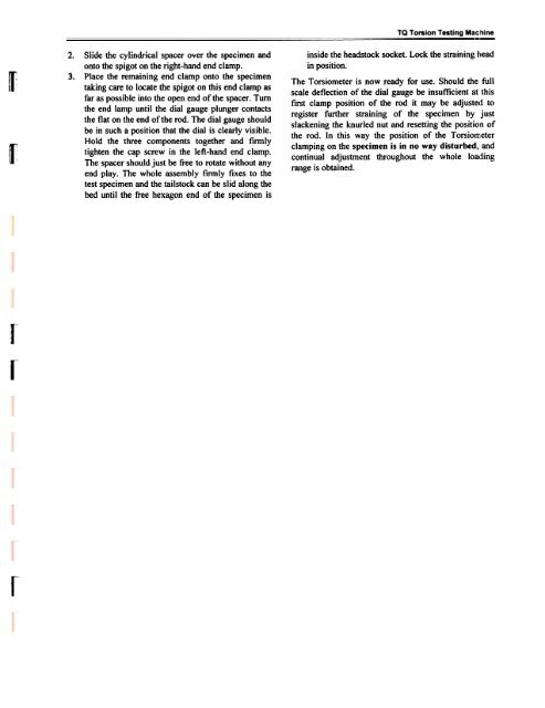
Slide the cylindrical spacer over the specimen and<br />
onto the spigot on the right-hand end clamp.<br />
Place the remaining end clamp onto the specimen<br />
taking care to locate the spigot on this end clamp as<br />
far as possible into the open end of the spacer. Turn<br />
the end lamp until the dial gauge plunger contacts<br />
the flat on the end of the rod. The dial gauge should<br />
be in such a position that the dial is clearly visible.<br />
Hold the three components together and ftTDlly<br />
tighten the cap screw in the left-hand end clamp.<br />
The spacer should just be free to rotate without any<br />
end play. The whole assembly firmly fixes to the<br />
test specimen and the tailstock can be slid along the<br />
bed until the free hexagon end of the specimen is<br />
inside the headstock socket. Lock the straining head<br />
in position.<br />
The Torsiometer is now ready for use. Should the full<br />
scale deflection of the dial gauge be insufficient at this<br />
first clamp position of the rod it may be adjusted to<br />
register further straining of the specimen by just<br />
slackening the knurled nut and resetting the position of<br />
the rod. In this way the position of the TorsioI11leter<br />
clamping on the specimen is in no way disturbed, and<br />
continual adjustment throughout the whole loading<br />
range is obtained.<br />
r<br />
r<br />
r


