Operational Manual - DCU
Operational Manual - DCU
Operational Manual - DCU

Create successful ePaper yourself
Turn your PDF publications into a flip-book with our unique Google optimized e-Paper software.
SECTION 2 ASSEMBLY<br />
The apparatus is despatched fully assembled except for<br />
the following:<br />
(a) Adjustable feet (2 oft)<br />
(b) Levelling handwheel and tie rod assembly<br />
(c) Counter assembly<br />
sufficient room to insert a specimen between the<br />
sockets.<br />
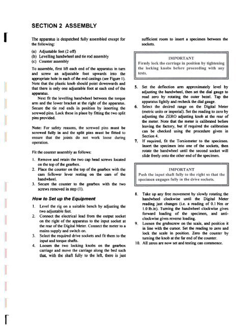
To assemble, first lift each end of the apparatus in turn<br />
and screw an adjustable foot upwards into the<br />
appropriate hole in each of the end castings (see Figure I).<br />
Note that the plastic knob should point downwards and<br />
that there is only one adjustable foot at each end of the<br />
apparatus.<br />
Next fit the levelling handwheel between the torque<br />
arm and the lower bracket at the right of the apparatus.<br />
Secure the tie rod ends in position by inserting the<br />
screwed pins. Lock these in place by fitting the two split<br />
pins provided.<br />
Note: For safety reasons, the screwed pins must be<br />
screwed fully in and the split pins must be fitted to<br />
ensure that the joints do not work loose during<br />
operation.<br />
7:<br />
Fit the counter assembly as follows:<br />
1. Remove and retain the two cap head screws located<br />
on the top of the gearbox.<br />
2. Place the counter on the top of the gearbox with the<br />
cam follower lever resting on the carn of the<br />
handwheel.<br />
3. Secure the counter to the gearbox with the two<br />
screws removed in step (1).<br />
How to Set up the Equipment<br />
I. Level the rig on a suitable bench by adjusting the<br />
two adjustable feet.<br />
2. Connect the electrical lead from the output socket<br />
on the right of the apparatus to the input socket at<br />
the rear of the Digital Meter. Connect the meter to a<br />
mains supply and switch on.<br />
3. Select the required drive sockets and fit them to the<br />
input and torque shafts.<br />
4. Loosen the two locking knobs on the gearbox<br />
carriage and move the carriage along the bed such<br />
that, with the shaft fully to the left, there is just<br />
s.<br />
6.<br />
Set the deflection ann approximately level by<br />
adjusting the handwheel, then set the dial gau~;e to<br />
read zero by rotating the outer bezel. Tap the<br />
apparatus lightly and recheck the dial gauge.<br />
Select the desired range on the Digital Nleter<br />
(metric units or imperial). Set the reading to zero by<br />
adjusting the ZERO adjusting knob at the rear of<br />
the meter. Note that the meter is calibrated ~:fore<br />
leaving the factory, but if required the calibration<br />
can be checked using the procedure given in<br />
Section 4.<br />
If required, fit the Torsiometer to the specunen.<br />
Insert the specimen into one of the sockets, then<br />
rotate the handwheel until the second socket will<br />
slide freely onto the other end of the specimen.<br />
8. Take up any free movement by slowly rotatin!~ the<br />
handwheel clockwise until the Digital Meter<br />
reading just changes (i.e. a reading of 0.1 Nm or<br />
1.0 lb. in). Turning the handwheel clockwise ~~ives<br />
forward loading of the specimen, and anticlockwise<br />
gives reverse loading.<br />
9. Loosen the grubscrew on the scale, and positi,:>n it<br />
in line with the cursor. Set the reading to zero and<br />
lock the scale in position. Zero the counter by<br />
turning the knob at the far end of the counter.<br />
10. All zeros are now set and testing can commenc