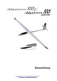
Agusta A119 Koala - Graupner
Agusta A119 Koala - Graupner
Agusta A119 Koala - Graupner

You also want an ePaper? Increase the reach of your titles
YUMPU automatically turns print PDFs into web optimized ePapers that Google loves.
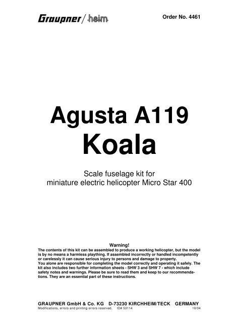
Order No. 4461<br />
<strong>Agusta</strong> <strong>A119</strong><br />
<strong>Koala</strong><br />
Scale fuselage kit for<br />
miniature electric helicopter Micro Star 400<br />
Warning!<br />
The contents of this kit can be assembled to produce a working helicopter, but the model<br />
is by no means a harmless plaything. If assembled incorrectly or handled incompetently<br />
or carelessly it can cause serious injury to persons and damage to property.<br />
You alone are responsible for completing the model correctly and operating it safely. The<br />
kit also includes two further information sheets - SHW 3 and SHW 7 - which include<br />
safety notes and warnings. Please be sure to read them and keep to our recommendations.<br />
They are an essential part of these instructions.<br />
GRAUPNER GmbH & Co. KG D-73230 KIRCHHEIM/TECK GERMANY<br />
Modifications, errors and printing errors reserved. ID# 53114 10/04
<strong>Agusta</strong> <strong>A119</strong> <strong>Koala</strong><br />
Foreword<br />
The AGUSTA <strong>A119</strong> "<strong>Koala</strong>" is a single-turbine helicopter designed for a wide range of tasks. It<br />
is largely based on the familiar twin-engined A109, but is fitted with only one turbine and a<br />
robust skid landing gear instead of the fixed or retractable wheeled undercarriage. The<br />
capacious cabin provides space for up to seven passengers, 1 tonne of freight or - in the rescue<br />
helicopter version - two stretchers. The Pratt & Whitney PT6B-37A turbine generates a take-off<br />
power of 1002 BHP and a continuous output of 872 BHP, giving the "<strong>Koala</strong>" an exceptional<br />
performance.<br />
This fuselage kit is designed to convert the MICRO STAR 400 mini electric helicopter into a<br />
semi-scale model of the AGUSTA <strong>A119</strong> "<strong>Koala</strong>" helicopter. The original MICRO STAR should<br />
first be test-flown and trimmed out completely. The chassis of the model, complete with tail<br />
boom and boom braces but without canopy and skid landing gear, is then screwed to a lightwood<br />
plywood base plate, to which a semi-scale broad-based skid landing gear is also<br />
attached. The fuselage, consisting of two lightweight vacuum-moulded shells, can then be fitted<br />
round this assembly. The shells are only glued together permanently at the tail end; at the front<br />
they are held together by strips of adhesive tape, so that the chassis can still be removed easily<br />
from the fuselage for maintenance work.<br />
The fuselage is vacuum-moulded from clear smoked-tint plastic, and is designed to be painted<br />
from the outside; the kit includes pre-cut masks for the windows.<br />
The flight battery can be changed through an opening in the bottom of the fuselage, without<br />
having to remove the fuselage shells.<br />
Naturally the flight time which can be achieved per battery charge varies according to the<br />
model’s set-up and the pilot’s flying style; however, since the "<strong>Koala</strong>" is around 100 g heavier<br />
than the basic MICRO STAR 400, you must expect the flight times to be correspondingly<br />
shorter.<br />
Note: in developing this fuselage kit we considered that minimum possible weight and minimum adverse effect<br />
on the model’s flight performance were more important than ease of building. For this reason you will need a<br />
reasonable level of modelling skill, care and patience in order to complete this model satisfactorily, particularly<br />
regarding the trimming and joining of the thin-walled fuselage shells.<br />
Specification<br />
Length excl. rotor approx. 645 mm<br />
Height approx.<br />
205 mm<br />
Width excl. rotor approx. 140 mm<br />
Main rotor Ø<br />
630 mm<br />
Tail rotor Ø<br />
140 mm<br />
All-up weight min. approx. 595 g<br />
Main rotor reduction ratio 13,2:1<br />
Tail rotor reduction ratio 4:1<br />
2
<strong>Agusta</strong> <strong>A119</strong> <strong>Koala</strong><br />
Warning notes<br />
• The contents of this kit can be assembled to produce a working model, but the model<br />
is by no means a harmless plaything. If assembled incorrectly or handled incompetently<br />
or carelessly it can cause serious injury to persons and damage to property.<br />
• When the model helicopter’s motor is running, the two rotors are spinning at high<br />
speed and contain an enormous quantity of rotational energy. Anything and everything<br />
that gets into the rotational plane of the rotors is either damaged or destroyed -<br />
and that includes parts of your body. Please take extreme care at all times with this<br />
machine.<br />
• If any object obstructs the rotational plane of the revolving rotors, severe damage will<br />
probably be caused to the rotor blades as well as the object. Broken parts may fly off<br />
and result in enormous imbalance; the whole helicopter then falls into sympathetic<br />
vibration, you lose control and have no way of predicting what the model will do next.<br />
• You may also lose control if a problem arises in the radio control system, perhaps as<br />
a result of outside interference, component failure or flat or faulty batteries, but in any<br />
case the result is the same: the model helicopter’s response is entirely unpredictable.<br />
Without prior warning it may move off in any direction.<br />
• Helicopters have many parts which are naturally subject to wear, including gearbox<br />
components, motor, ball-links etc., and as a result it is absolutely essential to check<br />
and maintain the model regularly. It is standard practice with full-size aircraft to give<br />
the machine a thorough "pre-flight check" before every flight, and this is equally important<br />
with your model helicopter. Constant checking gives you the opportunity to<br />
detect and correct any faults which may develop before they are serious enough to<br />
cause a crash.<br />
• The kit also includes two further information sheets - SHW 3 and SHW 7 - which include<br />
safety notes and warnings. Please be sure to read them and keep to our recommendations.<br />
They are an essential part of these instructions.<br />
• This helicopter is designed to be constructed and operated by adults, although young<br />
people of 16 years or more may do so under the instruction and supervision of competent<br />
adults.<br />
• The model features sharp points and edges which may cause injury.<br />
• Flying model aircraft is subject to certain legal restrictions, and these must be observed<br />
at all times. For example, it is essential to take out third party insurance, you<br />
must obtain permission to use the flying site, and you may have to obtain a licence to<br />
use your radio control system (regulations vary from country to country).<br />
• It is important to transport your model helicopter (e.g. to the flying site) in such a way<br />
that there is no danger of damaging the machine. Particularly vulnerable areas are the<br />
rotor head linkages and the tail rotor generally.<br />
3
<strong>Agusta</strong> <strong>A119</strong> <strong>Koala</strong><br />
• Controlling a model helicopter successfully is not easy; you will need persistence and<br />
determination to learn the skills, and good hand-eye co-ordination is a basic requirement.<br />
• Before you attempt to fly the model you should study the subject of helicopters in<br />
depth, so that you have a basic understanding of how the machines work. Read everything<br />
you can on the theory of helicopters, and spend as much time as you can<br />
watching other model helicopter pilots flying. Talk to chopper pilots, ask their advice,<br />
and enrol at a specialist model flying school if you need to. Many model shops will<br />
also be prepared to help you.<br />
• Please be sure to read right through these instructions before you start work on the<br />
model. It is important that you clearly understand each individual stage of assembly<br />
and the correct sequence of events before you begin building.<br />
• Don’t make modifications to the model’s construction by using parts other than those<br />
specifically recommended, unless you are certain of the quality and suitability of<br />
these other parts for the task.<br />
• We have made every effort to point out to you the dangers inherent in operating this<br />
model helicopter. Since neither we, the manufacturer, nor the model shop that sold<br />
you the kit have any influence over the way you build and operate your model, we are<br />
obliged to disclaim any liability in connection with it.<br />
Liability exclusion / Compensation<br />
As manufacturers, we at GRAUPNER are not in a position to influence the way you build<br />
and set up the model, nor how you install, operate and maintain the radio control system<br />
components. For this reason we are obliged to deny all liability for loss, damage or costs<br />
which are incurred due to the incompetent or incorrect use and operation of our products,<br />
or which are connected with such operation in any way.<br />
Unless otherwise prescribed by binding law, the obligation of the GRAUPNER company<br />
to pay compensation, regardless of the legal argument employed, is limited to the invoice<br />
value of that quantity of GRAUPNER products which was immediately and directly<br />
involved in the event which caused the damage. This does not apply if GRAUPNER is<br />
found to be subject to unlimited liability according to binding legal regulation on account<br />
of deliberate or gross negligence.<br />
4
<strong>Agusta</strong> <strong>A119</strong> <strong>Koala</strong><br />
Contents<br />
• Foreword ......................................... P.2<br />
• Warnings ......................................... P.3<br />
• Accessories, extra items required ....................... P.6<br />
• Building the base plate and landing gear .................. P.7<br />
• Grundplatte mit Landegestell anfertigen ................. P.7<br />
• Completing the chassis .............................. P.10<br />
• Preparing the fuselage shells .......................... P.11<br />
• Final trimming of the fuselage shell ...................... P.12<br />
• Horizontal stabilisers ................................. P.13<br />
• Completing and painting the model ...................... P.14<br />
• Centre of Gravity ................................... P.14<br />
• General safety measures .............................. P.15<br />
• Basic helicopter terminology............................ P.16<br />
• List of parts ........................................ P.18<br />
The instructions<br />
We have invested considerable effort in producing these instructions, with the aim of ensuring<br />
that your model helicopter will fly reliably and safely. Please take the trouble to follow the<br />
instructions step by step, exactly as described, as this guarantees a successful outcome. This<br />
applies to you whether you are a relative beginner or an experienced expert.<br />
• The comprehensive illustrations show how the model is constructed; be sure to read the<br />
instructions which accompany the drawings.<br />
• All gears, bearings and moving joints must be greased or oiled carefully.<br />
• You will find the parts list at the end of these instructions.<br />
5
<strong>Agusta</strong> <strong>A119</strong> <strong>Koala</strong><br />
Accessories<br />
Mechanics and recommended accessories for the AGUSTA <strong>A119</strong> <strong>Koala</strong><br />
Mechanics:<br />
MICRO STAR 400<br />
Order No. 4441<br />
Order No. 4441.RCU<br />
Factory-assembled model including motor<br />
As 4441, plus four servos, speed controller and gyro system<br />
Radio control system: see main <strong>Graupner</strong> catalogue<br />
We recommend a radio control system equipped with special helicopter options, or a microcomputer<br />
radio control system such as the mc-12, mc-14, mc-15, mc-19, mc / mx-22 or mc-24.<br />
Servos:<br />
C 121 micro-servo<br />
Order No. 5106<br />
Gyro system:<br />
PIEZO NT-310 pico gyro system<br />
Order No. 5134<br />
Speed controller:<br />
PICO SC 20<br />
Order No. 7160<br />
or<br />
PICO 25<br />
Order No. 7172<br />
Flight battery:<br />
LiPo 1500<br />
Order No. 7635.3BEC<br />
6
<strong>Agusta</strong> <strong>A119</strong> <strong>Koala</strong><br />
Assembly<br />
Preparing the chassis<br />
We assume that you have already test-flown your MICRO STAR 400 and set it up correctly.<br />
This is important, as access to the components for adjustment and maintenance is greatly<br />
restricted when the mechanics are inside the fuselage.<br />
• Remove the canopy (no longer required).<br />
• Remove the flight battery.<br />
• Unscrew the stabiliser panels from the mounting flanges.<br />
• Locate the self-tapping screws which retain the tail boom braces and unscrew them from the<br />
flange on the tail boom. Rotate the flange through 180° on the tail boom, so that the<br />
stabiliser mounting is on the underside, then re-fit the screws to secure the boom braces<br />
again.<br />
• Remove the speed controller from the underside of the chassis (it is re-installed later).<br />
• Unscrew the tail rotor bellcrank and disconnect it from the pushrod.<br />
• Loosen the clamping screws in the tail rotor housing, and withdraw the tail rotor housing to<br />
the rear.<br />
• Separate the skid landing gear (no longer required) from the chassis by undoing the four<br />
retaining screws. The screws are re-used.<br />
Building the base plate and landing gear<br />
The first step is to insert the two lateral stiffeners in both sides of the base plate, and fix them in<br />
place using cyano-acrylate adhesive ("cyano"). This is the procedure: lay the plate down flat and<br />
glue the stiffeners to the rear of the plate only. Allow the glue to set hard, then pack up the rear<br />
end by about 6 mm and glue the stiffeners to the front of the base plate, so that the plate takes<br />
up the same angle as the stiffeners.<br />
Glue the balsa in-fill piece to the underside of the base plate, flush with the rear edge. When the<br />
glue is dry, continue the circular opening in the base plate through the balsa. Round off the<br />
outside edges of the balsa in-fill piece as shown, using abrasive paper.<br />
7
<strong>Agusta</strong> <strong>A119</strong> <strong>Koala</strong><br />
Drill two 2 mm Ø holes in each of the carbon fibre skid tubes, taking care to drill at exactly the<br />
same angle: the rear ones should be 22 mm from the end, and the front ones spaced 135 mm<br />
from them. Caution: do not drill right through the tubes: just drill into them!<br />
Fit the two skid bars into the holes "dry" (no<br />
glue), and tape the skid tubes down on a flat<br />
surface as shown: the tubes should be 108<br />
mm apart, perfectly "square" and parallel to<br />
each other.<br />
Remove the skid bars from the skid tubes<br />
without disturbing the tubes, and slide lengths<br />
of 3 / 2 mm Ø plastic tube onto them; the ends<br />
of the steel bars should project by about 4<br />
mm; roughen the exposed ends using<br />
abrasive paper.<br />
Now fit the skid bars into the (still fixed) skid<br />
tubes, set them parallel to each other and tilted<br />
to the rear slightly, then glue them securely to<br />
the skid tubes using cyano.<br />
Glue a 20 mm long beech dowel in the front<br />
end of each carbon fibre tube, leaving half their<br />
length projecting.<br />
8
<strong>Agusta</strong> <strong>A119</strong> <strong>Koala</strong><br />
Measure a point 95 mm from the rear of the original aluminium skid tubes and cut them off at<br />
that point; the remaining curved front ends can now be pushed onto the wooden dowels in the<br />
carbon fibre skid tubes and glued in place. Align the curved ends so that they are parallel to<br />
each other, and check that they form a neat joint with the carbon fibre tubes. Allow the glue to<br />
cure fully.<br />
This completes the landing gear. Glue the assembly to the underside of the base plate as<br />
shown in the picture, taking care to position the plate centrally on the skid bars: tack the parts<br />
together using thin cyano initially, then apply thick cyano to strengthen the joints.<br />
9
<strong>Agusta</strong> <strong>A119</strong> <strong>Koala</strong><br />
Completing the chassis<br />
Attach the helicopter chassis (complete with tail boom and boom braces) to the base plate using<br />
the four screws with which the original skid landing gear was secured. Attach the speed<br />
controller to the underside of the base plate so that the ON / OFF switch is easily accessible<br />
when the model is complete.<br />
The upper bodywork stand-off pillars<br />
consist of a 70 mm length of 2 mm Ø<br />
carbon fibre rod. Drill a 2 mm Ø hole<br />
in both chassis side frames as shown<br />
in the photo, and push the rod<br />
through them. Adjust the position of<br />
the rod so that it projects by exactly<br />
the same amount on both sides. Cut<br />
two pieces 21 mm long from the 3 / 2<br />
mm Ø plastic tube, push them onto<br />
the carbon fibre rod as far as they will<br />
go, and secure them with cyano.<br />
10
<strong>Agusta</strong> <strong>A119</strong> <strong>Koala</strong><br />
Preparing the fuselage shells<br />
Cut out the vacuum-moulded fuselage shells, working exactly along the marked lines, and sand<br />
the cut edges smooth using fine abrasive paper.<br />
Using a sharp balsa knife, carefully cut out the rectangular turbine air intakes in the upper part<br />
of the fuselage, aft of the main rotor shaft. Seal the openings by gluing small pieces of fly screen<br />
over them on the inside; they serve as additional air openings to cool the motor.<br />
Cut the openings in the underside of the fuselage for the skid bars, working along the marked<br />
lines. In the top of the shells cut out as large an oval opening as possible for the main rotor<br />
shaft. At the tail end cut the hole for the tail rotor pushrod.<br />
Bend the tailskid to shape from the steel wire supplied; the correct shape is shown in the photo.<br />
Glue it in the bottom vertical stabiliser.<br />
Fit the fuselage shells together as accurately as possible and apply pieces of tape over the<br />
joints. Note that the edges of the shells should butt together; they should not overlap.<br />
11
<strong>Agusta</strong> <strong>A119</strong> <strong>Koala</strong><br />
When you are confident that everything lines up correctly and is held securely in place, the rear<br />
part of the shells can be glued together in the following areas only:<br />
• The top of tail boom along the shaft tunnel, then forward and up to just aft of the main rotor<br />
shaft;<br />
• The whole of the upper vertical stabiliser;<br />
• The whole tail cone;<br />
• The whole of the bottom vertical stabiliser.<br />
Do not allow the glue to run onto other areas, otherwise it may be impossible to install<br />
the mechanics when you have finished!<br />
Remove the strips of tape when the glue has set hard. Cut narrow strips of scrap plastic and cut<br />
them into short pieces as shown. Glue these small rectangles along the joint line in the front<br />
section of the fuselage, fitting them in groups of three to form locating tongues: in each case<br />
glue two pieces on the inside of one shell, with a third strip between them on the other side (see<br />
photo). Roughen all joints with abrasive paper before applying the glue.<br />
Final trimming of the fuselage shell<br />
Gently spread the fuselage shells on the underside so that the chassis can be installed from underneath.<br />
When you do this it is important to ensure that the tail rotor pushrod exits the fuselage<br />
through the appropriate opening. Check that the fuselage shell is a snug fit all round the chassis<br />
when the shells are held together with a few strips of adhesive tape: the openings at the bottom<br />
should be a close fit round the skid bars, but without placing the fuselage under strain. Check<br />
that the main rotor is free to rotate without any danger that the swashplate, pushrods or other<br />
linkage components could foul the fuselage.<br />
12
<strong>Agusta</strong> <strong>A119</strong> <strong>Koala</strong><br />
Slide the tail rotor assembly onto the tail boom again, working from the rear underside, and replace<br />
it in its original position. Trim the opening in the fuselage shell as required to ensure that<br />
none of the moving parts fouls the bodywork.<br />
Connect the tail rotor bellcrank to the pushrod, then replace the crank in its original position.<br />
Check that the tail rotor works correctly, with no tendency to foul or jam at any point.<br />
Mark the outline of the rectangular opening in the base plate on the fuselage shell, and cut it out<br />
so that the flight battery can be fitted from the underside and slid into the nose of the fuselage. If<br />
you wish, you can just leave this access hatch open; alternatively you can cut a rectangular<br />
hatch cover from scrap flat plastic sheet left over from the fuselage shells. The cover can be attached<br />
using a tape hinge, and held closed with another strip of tape.<br />
Horizontal stabilisers<br />
Cut out the cambered bottom shells for the horizontal stabilisers along the marked lines. Cut<br />
pieces of plastic tube to length and glue them in the two shells, 8 mm from the leading edge and<br />
parallel to it. Sand the edges of the open top surface of the stabiliser panels flat by rubbing them<br />
on a sheet of abrasive paper; it does not matter if you sand a little off the top of the plastic tubes<br />
at the same time.<br />
The prepared stabiliser shells can now be glued to the flat stabiliser top sections (scrap plastic).<br />
Allow the glue to set hard, then cut out the stabiliser panels and sand the glued edges smooth<br />
all round. Working from the angled root face of the panels, drill a 2 mm Ø hole into the plastic<br />
tube, and check that the remainder of the 2 mm carbon fibre rod can be slid into the two tubes.<br />
13
<strong>Agusta</strong> <strong>A119</strong> <strong>Koala</strong><br />
Drill 2 mm Ø holes at the marked points in the tail boom so that the carbon fibre rod can be<br />
fitted through them; the rod acts as the horizontal stabiliser joiner and spar. Fit the stabiliser<br />
panels on the joiner rod, and check that they are horizontal when viewed from the tail. At the<br />
same time ensure that they rest snugly against the fuselage sides.<br />
When you are confident that everything fits correctly, remove the stabiliser panels, remove the<br />
strips of tape holding the fuselage shells together, and remove the chassis from the fuselage<br />
once more.<br />
Completing and painting the model<br />
The fuselage should be painted on the outside using fast-drying spray paint.<br />
Caution:<br />
In order to save weight the fuselage shells are moulded in very thin plastic. This makes<br />
them vulnerable to distortion caused by the softening action of the paint solvent. You<br />
can avoid this happening by applying the paint sparingly, in thin coats.<br />
Before applying the paint, you must mask out the windows using the pre-cut self-adhesive<br />
masks provided in the kit. Rub down the surfaces to be painted using very fine abrasive paper<br />
(600 - 1200 grit) to ensure that the paint adheres well. This is particularly important along the<br />
joint line; if you neglect this, the paint may tend to flake off later when you peel off the adhesive<br />
tape which is used to hold the fuselage shell halves together.<br />
We recommend that you paint the horizontal stabiliser panels separately from the fuselage, and<br />
only attach them to the model when painting is complete. The same applies to the vacuummoulded<br />
dummy exhaust pipes.<br />
Cut out the decals from the sheet supplied, and apply them to the model in the arrangement<br />
shown in the kit box illustration. The best way of fitting the black window frames is to cut them<br />
out initially along the outside edges only, and apply them to the model in this state. Then you<br />
can cut carefully along the inside lines and peel off the excess material.<br />
Centre of Gravity<br />
The model’s CG should be as close as possible to the main rotor shaft, but up to 2 cm aft of it<br />
should not present problems. The CG can be corrected by adding lead ballast to the extreme<br />
fuselage nose, but since this adds unwanted weight it should only be done if there is really no<br />
alternative.<br />
14
<strong>Agusta</strong> <strong>A119</strong> <strong>Koala</strong><br />
General safety measures<br />
• Take out adequate third-party insurance cover.<br />
• Wherever possible join the local model flying club.<br />
At the flying site:<br />
• Never fly your model above spectators.<br />
• Do not fly models close to buildings or vehicles.<br />
• Avoid flying over agricultural workers in neighbouring fields.<br />
• Do not fly your model in the vicinity of railway lines, major roads or overhead cables.<br />
Pre-flight checks, flying safety:<br />
• Before you switch on the transmitter check carefully that no other model flyer is using the<br />
same frequency.<br />
• Carry out a range check with your RC system.<br />
• Check that the transmitter and flight batteries are fully charged.<br />
• Do not let the model fly out of safe visual range.<br />
Post-flight checks<br />
• Clean the model and check that all screws etc. are still tight.<br />
• Look for wear and damage to the helicopter, and replace worn parts in good time.<br />
• Ensure that the electronic components such as battery, receiver, gyro etc. are still securely<br />
fixed. Remember that rubber bands deteriorate with age and may fail.<br />
• Check the receiver aerial. Conductor fractures inside the insulation are often not visible from<br />
the outside.<br />
• If the main rotor should touch the ground when spinning, replace the blades. Internal blade<br />
damage may not be visible from the outside.<br />
• Never carry the model by the tail boom: too firm a grip will easily deform the tail rotor<br />
pushrod.<br />
15
<strong>Agusta</strong> <strong>A119</strong> <strong>Koala</strong><br />
Some basic terms used in model helicopter flying<br />
The term "rotary wing machine" indicates that the helicopter’s lift is derived from rotating "wings"<br />
which take the form of rotor blades. As a result, a helicopter does not require a minimum forward<br />
speed in order to fly, i.e. it can hover.<br />
Cyclic pitch<br />
Cyclic pitch variation is used to steer the machine around the roll and pitch axes. Changing cyclic<br />
pitch has the effect of altering blade pitch depending on its position in the circle. The effect<br />
is caused by tilting the swashplate, which then effectively tilts the helicopter in the required direction.<br />
Collective pitch<br />
Collective pitch provides control over vertical movement, i.e. for climb and descent. The pitch of<br />
both rotor blades is altered simultaneously.<br />
Torque compensation<br />
The spinning rotor produces a moment which tends to turn the whole helicopter in the opposite<br />
direction. This effect must be accurately neutralised, and this is the task of the tail rotor. Tail rotor<br />
blade pitch is altered to vary torque compensation. The tail rotor is also used to control the<br />
model around the vertical (yaw) axis.<br />
Hovering<br />
This is the state in which the helicopter flies in a fixed position in the air, without moving in any<br />
direction.<br />
Ground effect<br />
This occurs only when the machine is close to the ground, and it falls off as altitude rises. At an<br />
altitude of about 1 - 1½ times the rotor diameter ground effect is completely absent. Normally<br />
the revolving airflow from the main rotor is able to flow away freely, but in ground effect the air<br />
strikes an obstacle (the ground) and forms an "air cushion". In ground effect a helicopter can lift<br />
a greater weight, but its positional stability is reduced, with the result that it tends to "break<br />
away" in an unpredictable direction.<br />
Climb<br />
Any excess power above that required for hovering can be exploited to make the helicopter<br />
climb. Note that a vertical climb requires more energy than an angled climb which includes forward<br />
motion. For this reason a model with a given amount of motor power will climb more rapidly<br />
at an angle than vertically.<br />
Level flight<br />
A helicopter absorbs least power when flying straight and level at about half-power. If you have<br />
trimmed the machine carefully for a steady hover, it will tend to turn to one side when flown forward.<br />
The reason for this phenomenon is that the rotor blade which is moving forward encounters<br />
an increased airflow caused by the wind, and this increases its upthrust compared with the<br />
blade which is moving downwind, where the same airflow has to be subtracted. The net result is<br />
a lateral inclination of the helicopter.<br />
Descent<br />
If the helicopter’s rotor speed is relatively low and you place the helicopter in a fast vertical descent,<br />
the result can be that insufficient air flows through the rotor. This can cause what is<br />
known as a "turbulent ring stage", when the airflow over the blade airfoil breaks away. The helicopter<br />
is then uncontrollable and will usually crash. A high-speed descent is therefore only possible<br />
if the helicopter is moving forward, or if the rotor is spinning at high speed. For the same<br />
reason care should be exercised when turning the model helicopter downwind after flying into<br />
wind.<br />
Flapping motion of the rotor blades<br />
As we have already seen, the forward-moving blade produces greater upthrust than the trailing<br />
blade. This effect can be minimised by allowing the leading blade to rise and the trailing blade to<br />
fall. The rotor head is fitted with what is known as a flapping hinge to allow this movement, and<br />
16
<strong>Agusta</strong> <strong>A119</strong> <strong>Koala</strong><br />
this prevents the rotor plane tilting excessively in forward flight. In model helicopters a single<br />
hinge shared by both blades has proved an effective solution to the problem.<br />
Auto-rotation<br />
This term refers to a helicopter flying without motor power. The rotational speed of the main rotor<br />
can be kept high by setting both blades to negative pitch, and the airflow through the rotor as<br />
it descends then keeps the blades turning. The rotational energy stored in the rotor by this<br />
means can be converted into upthrust when the helicopter is close to the ground, by the pilot<br />
applying positive collective pitch. Of course, this can only be done once, and it has to be done at<br />
the correct moment. Auto-rotation allows a model helicopter to land safely when the motor fails,<br />
just like a full-size machine.<br />
However, auto-rotation places considerable demands on the pilot’s judgement and reflexes; you<br />
can only halt the machine’s descent once, and you must not "flare" too early or too late. Much<br />
practice is required to get it right.<br />
17
<strong>Agusta</strong> <strong>A119</strong> <strong>Koala</strong><br />
List of parts<br />
Part<br />
Description Material / dimensions in mm No. off<br />
No.<br />
1 Fuselage shell, right / left Clear plastic, smoked tint 1 each<br />
2 Horizontal stabiliser, bottom shell, Clear plastic, smoked tint<br />
1 each<br />
right / left<br />
3 Horizontal stabiliser, top panel,(scrap Clear plastic, smoked tint<br />
1 each<br />
material from parts 1)<br />
approx. 55 x 25<br />
4 Battery hatch cover<br />
Clear plastic, smoked tint<br />
1<br />
(scrap material from parts 1) approx. 55 x 40<br />
5 Dummy exhaust pipes Clear plastic, smoked tint 2<br />
6 Chassis base plate Beech ply, approx. 240 x 60 x 1,5 1<br />
7 Lateral chassis stiffener Beech ply, approx. 205 x 12 x 1,5 2<br />
8 In-fill piece Balsa, 60 x 40 x 6 1<br />
9 Skid bar, front / rear Pre-formed piano wire 1 each<br />
10 Skid bar sheath ABS tube, 2/3 Ø x 135 2<br />
11 Skid tube CFRP tube, 5/3 Ø x 170 2<br />
11 Skid tube tips Nose of aluminium skid tube, 5/4 Ø 2<br />
12 Skid joiner Beech dowel, 3 Ø x 20 2<br />
13 Stand-off pillar CFRP rod, 2 Ø x 70 1<br />
14 Horizontal stabiliser joiner CFRP rod, 2 Ø x 130 1<br />
15 Fly screen Plastic, 50 x 50 1<br />
16 Tailskid piano wire, 1 Ø x 100 1<br />
17 Window masks Masking film, pre-cut 1<br />
18 Full-colour decal sheet 1<br />
18