1 CATALOGO LIVELLI A VETRO inglese
1 CATALOGO LIVELLI A VETRO inglese
1 CATALOGO LIVELLI A VETRO inglese

You also want an ePaper? Increase the reach of your titles
YUMPU automatically turns print PDFs into web optimized ePapers that Google loves.
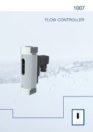
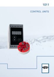
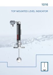
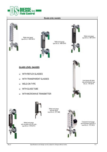
GLASS LEVEL GAUGES<br />
Reflex level gauge<br />
type DS LG - RDR GR18<br />
Reflex level gauge<br />
type DS LG - RBR GR18<br />
Reflex level gauge<br />
type DS LG - RBF GR18<br />
GLASS LEVEL GAUGES<br />
<br />
<br />
<br />
<br />
<br />
WITH REFLEX GLASSES<br />
WITH TRANSPARENT GLASSES<br />
WELD-ON TYPE<br />
WITH GLASS TUBE<br />
WITH MICROWAVE TRANSMITTER<br />
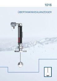
Level gauge with glass<br />
tube and protection type<br />
DS LG - TVR GR18<br />
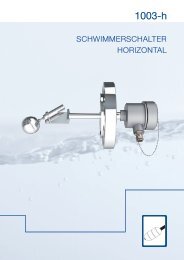
Reflex level gauge<br />
with ball valves<br />
type DS LG - RTF SBB<br />
Reflex level gauge<br />
with monolithic shut-off cocks<br />
type DS LG - RTR MT18<br />
Transparent level gauge<br />
with illumination lamp EEx d<br />
type DS LG - TPF GR18<br />
Rev.0 Specifications and design can be subject to change without notice 1.1
GLASS LEVEL GAUGES<br />
Glass level gauges give very accurate level readings, making them the ideal product for calibrating other instruments as well.<br />
They play a crucial role during system start-up.<br />
To recommend the most suitable level gauge for a particular purpose,<br />
please provide the following data when asking for advice or a quotation.<br />
* essential data<br />
• * CENTRE-TO-CENTRE DISTANCE (distance between process connections)<br />
• MINIMUM VISIBLE LENGTH REQUIRED<br />
• * TYPE OF CONNECTIONS (flanged-threaded-weld-on) and related<br />
STANDARDS (UNI-ANSI-DIN…)<br />
• POSITION OF PROCESS CONNECTIONS<br />
• POSITION OF THE VALVE HANDLING<br />
• * REQUIRED MATERIAL (wetted and non-wetted parts)<br />
• * TYPE OF FLUID<br />
• * DESIGN AND MAXIMUM OPERATING PRESSURES<br />
• * DESIGN AND MAXIMUM OPERATING TEMPERATURES<br />
• ANY ADDITIONAL ACCESSORIES<br />
READING TYPE<br />
The required visible length depends on the type of fluid and the shape of the tank.<br />
The visible length with a single glass varies from 95 mm to 320 mm. If the required visible length exceeds these measurements, additional glasses of<br />
the same length are joined together and mounted on a single bar.<br />
To ensure continuous reading along a housing consisting of numerous glasses, one or more housings can be placed on the side at the points where the<br />
reading is interrupted.<br />
Single housing Multiple housing Multiple housing with continuous reading<br />
Rev.0 Specifications and design can be subject to change without notice 1.2
GLASS LEVEL GAUGES<br />
Code<br />
1 Basic Type<br />
DS LG<br />
DIESSE Glass level gauge<br />
2 Level Gauge Model<br />
Pos. 1: Level Gauge type Pos. 2: No. of sections Pos. 3: Glass size / type<br />
RTR Reflex - rotating execution with tubular cover<br />
RTF Reflex - fixed distance execution with tubular cover<br />
RBR Reflex - rotating execution with lateral covers<br />
RBF Reflex - fixed distance execution with lateral covers<br />
RCR Reflex - rotating execution with light cover<br />
RDR Reflex - rotating execution with light cover - flat body Options Pos. 3<br />
RCF Reflex - fixed distance execution with light cover Standard Type A<br />
RPF Reflex - fixed distance execution with heavy cover /B Type B<br />
RXF Reflex - fixed distance execution with heavy cover - flat body /RV Right View<br />
TCR Transparent - rotating execution with light cover /LV Left View<br />
TMR Transparent - rotating execution with light cover - flat body /MS Glass protection with MICA shields<br />
TCF Transparent - fixed distance execution with light cover /KFS Glass protection with ECTFE shields<br />
TMF Transparent - fixed distance execution with light cover - flat body<br />
TPF Transparent - fixed distance execution with heavy cover<br />
TXF Transparent - fixed distance execution with heavy cover - flat body<br />
RCW Reflex - weld-on type with light cover<br />
TCW Transparent - weld on type with light cover<br />
TVR Tubular glass type<br />
3 Process connections<br />
Pos. 1: Nominal dimension Pos. 2: Nominal pressure Pos. 3: Type / Finish Pos. 4: Position<br />
Standard Side / Side<br />
/SB Side / Bottom<br />
/TS Top / Side<br />
/TB Top / Bottom<br />
4 Gauge Valves model<br />
Pos. 1: Type of valves<br />
Pos. 2: Drain and Vent connection<br />
0 None 0 Blind<br />
PB Plug BSP<br />
GR18 Cylindrical plug cocks PT Plug NPT<br />
FL Flange<br />
MT18 Cylindrical plug cocks - Monolithic body D12 Cylindrical plug cock (Standard)<br />
D18 Cylindrical plug cock<br />
NPV Push button valves PM18 Three way cylindrical plug manometer setting valve with control flange<br />
SHV Globe valves DHV Globe valve<br />
SBB Ball valves DBB Ball valve<br />
5 Distance Centre-to-centre<br />
M… Distance between connections centres in mm<br />
M [SL…HL] Standard distance: see table in each level type form<br />
6 Materials<br />
Pos. 1: Wetted parts Pos. 2: Non-wetted parts Pos. 3: Gaskets<br />
CS Carbon steel ASTM A105 galvanized CS Carbon steel galvanized Standard Graphite / Copper<br />
LF2 Carbon steel A105 LF2 galvanized SS Stainless steel AISI 316 GF Graphite / AISI 316<br />
SS Stainless steel AISI 316L PF PTFE/316<br />
GG EPDM (for glass tube)<br />
7 Accessories<br />
LC Lower check ball UC Upper check ball LUC Check balls (lower + upper)<br />
LPH Lower pusher UPH Upper pusher LUPH Pusher (lower + upper)<br />
VSG Calibrated scale NFE Non-frosting extension CR… Continuous reading<br />
MLA Minimum level arrow EVA50 Bulb type illuminator TDR Microwave transmitter<br />
GPU Glass tube protection MJT Middle terminal for glass tube ELC Remote control<br />
LFC Weight closing for lower handle UFC Weight closing for upper handle LUFC Weight closing for all handles (lower + upper)<br />
SMHD Cocks handles lock (all ) LU-SMHD Shut-off cocks handles lock D/V-SSHD Vent and drain handles lock<br />
8 Approvals<br />
EEx ATEX SHP… Marine<br />
Code 1 2 3 4 5 6 7 8<br />
e.g. DS LG - RBR17 - 20/40/RF - GR18/D12/0 - M 420 - CS/CS - LC/VSG - EEx<br />
Rev.0 Specifications and design can be subject to change without notice 1.3
Rev.0 Specifications and design can be subject to change without notice 1.4
REFLEX LEVEL GAUGES<br />
The level is ascertained using a glass which has a smooth side and a wetted prismatic side. The level of the fluid inside the level gauge is shown by<br />
using the optical principles of refraction: the wetted part fully absorbs light and so the fluid appears to be black. The part in contact with the gas, on the<br />
other hand, fully reflects light and so the gas appears to be of a very light colour.<br />
The product line includes level gauges suitable for pressure ratings from PN10 to PN160 and a huge number of industrial process applications.<br />
This type of gauge is recommended:<br />
for taking clear and simple readings (see counter-indications below)<br />
if you are looking for an inexpensive gauge which will also save you money on<br />
maintenance costs<br />
Operating limits / Conditions:<br />
Process:<br />
Max. pressure: 160 bar @ 38°C (with GR18, MT18 or SHV type valves)<br />
Max. temperature: 300°C (max. temperature allowed by borosilicate glasses as per the<br />
DIN 7081 standard - see page 1.69)<br />
Steam: (see page 1.59)<br />
Max. pressure: 22 bar (with GR18, MT18 or SHV type valves)<br />
Max. temperature: 216°C (saturated steam @ 22 bar)<br />
For saturated steam values > 20 bar, a low-maintenance transparent level gauge<br />
with mica shield protection should be used (see graph "glass loss caused by<br />
boiler water" for the estimated glass life).<br />
Not only does the glass life depend on the temperature, it depends on the pH of<br />
the water (the higher the value, the shorter the glass life).<br />
The product is NOT suitable for use in the following instances:<br />
if exposed to corrosive fluid (e.g. caustic soda, hydrofluoric acid, citric acid ...)<br />
if exposed to high pressure steam<br />
if subjected to repeated thermal shocks<br />
In the scenarios listed above, the glass must be protected with MICA or PCTFE shields, so a transparent level gauge is necessary<br />
for checking the level of separation between two immiscible fluids (interface)<br />
for checking the colour of a fluid (all fluids look very dark)<br />
in cases where the fluid is particularly viscous (a film may form on the glass which prevents you from taking an accurate reading)<br />
in cases where the fluid is particularly dark (the reflex principle is rendered ineffective)<br />
Types:<br />
PN16 PN25/40 PN40/64 PN40/64 PN100/160 PN160<br />
Class 150 Class 300 Class 300 Class 600/900 Class 900<br />
Rev.0 Specifications and design can be subject to change without notice 1.5
REFLEX LEVEL GAUGES<br />
Materials / Specifications:<br />
Connections between housing and cocks:<br />
- with grinded pipes and stuffing box (view can be turned by the customer during installation)<br />
- fixed centre-to-centre distance with metal seal (view can be turned during manufacture)<br />
Wetted parts:<br />
- standard: galvanized ASTM A105 or A105 LF2 carbon steel, ASTM A182 F316L stainless steel<br />
- additional options: on request<br />
Non-wetted parts:<br />
- standard: galvanized carbon steel, AISI 316/316L stainless steel<br />
- additional options: on request<br />
Gaskets: (see page 1.71)<br />
- standard: graphite/copper (ASTM A105), graphite/AISI 316 (A105 LF2 and ASTM A182 F316L)<br />
- additional options: PTFE; other extras on request<br />
Glasses: (see page 1.69)<br />
- reflex borosilicate glasses, thermally pre-stressed and extra hard as per the DIN 7081 standard<br />
Shut-off: (see page 1.49)<br />
- standard: upper valve and lower valve (side/side)<br />
- additional options: on request<br />
Drain: (see page 1.50)<br />
- standard: threaded valve<br />
- additional options: on request<br />
Vent: (see page 1.50)<br />
- standard: blind (for grinded pipes version)<br />
- threaded with plug (for fixed centre-to-centre version)<br />
- additional options: on request<br />
Tank connections:<br />
Flanged:<br />
- UNI standard: PN40 DN15 / DN20 / DN25<br />
- ANSI standard: #150 / #300 / #600 DN ½” / ¾” / 1”<br />
- additional options: on request<br />
Threaded:<br />
- BSP (GAS) standard: ½”-M / ¾”-M<br />
- NPT standard: ½”-M / ¾”-M<br />
Weld-on: from ½” to 1” BW or SW<br />
Option: further connections type or direct connections to the process without shut-off cocks (see page 1.49 for more details)<br />
Shut-off cocks, drain cock and vent cock:<br />
- Cylindrical plug cocks (type GR18 or MT18 - see page 1.47)<br />
- Globe valves (type SHV - see page 1.48)<br />
- Push-button valves (type NPV - see page 1.48)<br />
- Ball valves (type SBB)<br />
Spare parts:<br />
Our spare parts are interchangeable with those of major international manufacturers.<br />
For the full range of complete sets, turn to the spares section on page 1.69.<br />
Accessories:<br />
Lower and/or upper safety ball, pusher for safety ball, calibrated scale, non-frosting extension, minimum level arrow, continuous reading, cocks handles<br />
lock (see page 1.55 for details)<br />
Certifications (On request):<br />
- ATEX<br />
- Tests and inspection by Notified Bodies<br />
- NACE MR0175<br />
- Others on request<br />
All DIESSE products are individually checked and tested in accordance with company quality procedures and the industry regulations<br />
currently in effect.<br />
Certificates can be issued on request.<br />
Rev.0 Specifications and design can be subject to change without notice 1.6
Technical data<br />
Service conditions<br />
Max Pressure: PN25 and PN40<br />
Max Temperature: 280/300°C (According to DIN 7081 for glasses, see page 1.69)<br />
GLASS LEVEL GAUGE<br />
REFLEX TYPE<br />
PN25 and PN40 / Class 150<br />
DS LG - RBR GR18<br />
Code: DS LG RBR…-… /40/RF-GR18/…/…-M…-CS/CS<br />
View<br />
Standard: adjustable on 360° in the installation phase<br />
Distance (Centre-to-centre)<br />
Standard: see below table (Distance adjustable - 0 mm / + 10 mm)<br />
Option: On request intermediate distances and over 3.000 mm<br />
Materials (Standard)<br />
Execution: CS/CS SS/CS<br />
Gauge body & cocks body: ASTM A105 AISI 316L<br />
Cocks trim: AISI 303 AISI 316<br />
Non-wetted parts: Carbon steel galvanized Carbon steel galvanized<br />
Gaskets<br />
Standard: grahite/copper<br />
Option: graphite/AISI 316 or PTFE/AISI316<br />
Shut-off cocks<br />
Type DS GR18: cylindrical plug type - Straight type - Quick 90° closing<br />
Type DS MT18: cylindrical plug type with monolithic body - Straight type - Quick 90° closing<br />
(see page 1.47) Centre-to-centre distance M = B + 115 mm or 140 mm<br />
Handling: lever operated with PP handle (Standard: right; Option: left)<br />
Process connections:<br />
Standard flanges: UNI PN40 DN15-20-25 ANSI#150-300-600/RF DN ½“ - ¾“ - 1“<br />
Standard threaded unions: BSP-M ½” - ¾” NPT-M ½” - ¾”<br />
Options: further connections types or direct connections to the process without shut-off cocks<br />
(see page 1.49)<br />
Vent: Standard: blind Option: see page 1.50<br />
Drain: Standard: cock type D12 threaded ½” Option: see page 1.50<br />
Glasses<br />
Reflex - Borosilicate glass, “extra hard” and thermally pre-stressed - According to DIN 7081<br />
Standard: fitted with type A (see page 1.69) Option: type B (see page 1.69)<br />
Accessories<br />
See from page 1.55<br />
Weights<br />
Housing type DS RBR: see below table<br />
Cocks type DS GR18: Kg. 7,4 approx. (with flanges UNI DN20 PN40)<br />
Tightening torque of housing screws<br />
Standard: 40 Nm<br />
Spare parts<br />
Housing type DS RBR: see from page 1.69 (drawing with components and parts list see page 1.61)<br />
Cocks type DS GR18: see from page 1.72 (drawing with components and parts list see pag. 1.66)<br />
CODE TYPE BODY DISTANCE SL DISTANCE HL VISIBLE GLASS WEIGHT<br />
Length Pipes L = 57 Pipes L = 72 Length Length Housing<br />
[mm] -0/+10 mm -0/+10 mm [mm] [mm] [Kg]<br />
x No. el B M = B+105 M = B+130 VL x No. elements<br />
11 1x1 130 235 260 95 115x1 2,4<br />
12 2x1 155 260 285 120 140x1 2,8<br />
13 3x1 180 285 310 145 165x1 3,3<br />
14 4x1 205 310 335 170 190x1 3,8<br />
15 5x1 235 340 365 200 220x1 4,3<br />
16 6x1 265 370 395 230 250x1 4,9<br />
17 7x1 295 400 425 260 280x1 5,4<br />
18 8x1 335 440 465 300 320x1 6,1<br />
19 9x1 360 465 490 320 340x1 6,6<br />
24 4x2 410 515 540 375 190x2 7,5<br />
25 5x2 470 575 600 435 220x2 8,5<br />
26 6x2 530 635 660 495 250x2 9,7<br />
27 7x2 590 695 720 555 280x2 10,7<br />
28 8x2 670 775 800 635 320x2 12,1<br />
29 9x2 720 825 850 680 340x2 13,1<br />
36 6x3 795 900 925 760 250x3 14,4<br />
37 7x3 885 990 1015 850 280x3 15,9<br />
38 8x3 1005 1110 1145 970 320x3 18,0<br />
39 9x3 1080 1185 1210 1040 340x3 19,5<br />
47 7x4 1180 1285 1310 1145 280x4 21,2<br />
48 8x4 1340 1445 1470 1305 320x4 24,0<br />
49 9x4 1440 1545 1570 1400 340x4 26,0<br />
57 7x5 1475 1580 1605 1440 280x5 26,5<br />
58 8x5 1675 1780 1805 1640 320x5 30,0<br />
59 9x5 1800 1905 1930 1760 340x5 32,5<br />
68 8x6 2010 2115 2140 1975 320x6 35,9<br />
69 9x6 2160 2265 2290 2120 340x6 38,9<br />
78 8x7 2345 2450 2475 2310 320x7 41,9<br />
79 9x7 2520 2625 2650 2480 340x7 45,4<br />
88 8x8 2680 2785 2810 2645 320x8 47,9<br />
89 9x8 2880 2985 3010 2840 340x8 51,9<br />
Tab. RBR<br />
Rev.0 Specifications and design can be subject to change without notice 1.7
Technical data<br />
Service conditions<br />
Max Pressure: PN25 and PN40<br />
Max Temperature: 280/300°C (According to DIN 7081 for glasses, see page 1.69)<br />
GLASS LEVEL GAUGE<br />
REFLEX TYPE<br />
PN25 and PN40 / Class 150<br />
DS LG - RBF GR18<br />
Code: DS LG RBF…-… /40/RF-GR18/…/…-M…-CS/CS<br />
View<br />
Standard: front, on request lateral (right or left) adjustable in the production phase<br />
Distance (Centre-to-centre)<br />
Standard: see below table for mimimum distance (Fixed distance, not adjustable)<br />
Option: On request intermediate distances and over 3.000 mm<br />
Materials (Standard)<br />
Execution: CS/CS SS/CS<br />
Gauge body & cocks body: ASTM A105 AISI 316L<br />
Cocks trim: AISI 303 AISI 316<br />
Non-wetted parts: Carbon steel galvanized Carbon steel galvanized<br />
Gaskets<br />
Standard: grahite/copper<br />
Option: graphite/AISI 316 or PTFE/AISI316<br />
Shut-off cocks<br />
Type DS GR18: cylindrical plug type - Straight type - Quick 90° closing<br />
Handling: lever operated with PP handle (Standard: right; Option: left)<br />
Process connections:<br />
Standard flanges: UNI PN40 DN15-20-25 ANSI#150-300-600/RF DN ½“ - ¾“ - 1“<br />
Standard threaded unions: BSP-M ½” - ¾” NPT-M ½” - ¾”<br />
Options: further connections types or direct connections to the process without shut-off cocks<br />
(see page 1.51)<br />
Vent: Standard: threaded ½” with plug Option: see page 1.52<br />
Drain: Standard: cock type D12 threaded ½” Option: see page 1.52<br />
Glasses<br />
Reflex - Borosilicate glass, “extra hard” and thermally pre-stressed - According to DIN 7081<br />
Standard: fitted with type A (see page 1.69) Option: type B (see page 1.69)<br />
Accessories<br />
See from page 1.55<br />
Weights<br />
Housing type DS RBF: see below table<br />
Cocks type DS GR18: Kg. 7,4 approx. (with flanges UNI DN20 PN40)<br />
Tightening torque of housing screws<br />
Standard: 40 Nm<br />
Spare parts<br />
Housing type DS RBR: see from page 1.69 (drawing with components and parts list see page 1.61)<br />
Cocks type DS GR18: see from page 1.72 (drawing with components and parts list see pag. 1.66)<br />
CODE TYPE BODY DISTANCE SL VISIBLE GLASS WEIGHT<br />
Length MINIMUM Length Length Housing<br />
[mm] [mm] [mm] [mm] [Kg]<br />
x No. el B M = B+40 VL x No. elements<br />
11 1x1 130 170 95 115x1 3,7<br />
12 2x1 155 195 120 140x1 4,1<br />
13 3x1 180 220 145 165x1 4,6<br />
14 4x1 205 245 170 190x1 5,1<br />
15 5x1 235 275 200 220x1 5,6<br />
16 6x1 265 305 230 250x1 6,2<br />
17 7x1 295 335 260 280x1 6,7<br />
18 8x1 335 375 300 320x1 7,4<br />
19 9x1 360 400 320 340x1 7,9<br />
24 4x2 410 450 375 190x2 8,8<br />
25 5x2 470 510 435 220x2 9,8<br />
26 6x2 530 570 495 250x2 11,0<br />
27 7x2 590 630 555 280x2 12,0<br />
28 8x2 670 710 635 320x2 13,4<br />
29 9x2 720 760 680 340x2 14,4<br />
36 6x3 795 835 760 250x3 15,7<br />
37 7x3 885 925 850 280x3 17,2<br />
38 8x3 1005 1045 970 320x3 19,3<br />
39 9x3 1080 1120 1040 340x3 20,8<br />
47 7x4 1180 1220 1145 280x4 22,5<br />
48 8x4 1340 1380 1305 320x4 25,3<br />
49 9x4 1440 1480 1400 340x4 27,3<br />
57 7x5 1475 1515 1440 280x5 27,8<br />
58 8x5 1675 1715 1640 320x5 31,3<br />
59 9x5 1800 1840 1760 340x5 33,8<br />
68 8x6 2010 2050 1975 320x6 37,2<br />
69 9x6 2160 2200 2120 340x6 40,2<br />
78 8x7 2345 2385 2310 320x7 43,2<br />
79 9x7 2520 2560 2480 340x7 46,7<br />
88 8x8 2680 2720 2645 320x8 49,3<br />
89 9x8 2880 2920 2840 340x8 53,2<br />
Tab. RBF<br />
Rev.0 Specifications and design can be subject to change without notice 1.8
Technical data<br />
Service conditions<br />
Max Pressure: PN40<br />
Max Temperature: 280/300°C (According to DIN 7081 for glasses, see page 1.69)<br />
GLASS LEVEL GAUGE<br />
REFLEX TYPE<br />
PN40<br />
DS LG - RCR GR18<br />
Code: DS LG RCR…-… /40/RF-GR18/…/…-M…-CS/CS<br />
View<br />
Standard: adjustable on 360° in the installation phase<br />
Distance (Centre-to-centre)<br />
Standard: see below table (Distance adjustable - 0 mm / + 10 mm)<br />
Option: On request intermediate distances and over 3.000 mm<br />
Materials (Standard)<br />
Execution: CS/CS SS/CS SS/SS<br />
Gauge body & cocks body: ASTM A105 AISI 316L AISI 316L<br />
Cocks trim: AISI 303 AISI 316 AISI 316<br />
Non-wetted parts: Carbon steel galvanized Carbon steel galvanized AISI 316<br />
Gaskets<br />
Standard: grahite/copper<br />
Option: graphite/AISI 316 or PTFE/AISI316<br />
Shut-off cocks<br />
Type DS GR18: cylindrical plug type - Straight type - Quick 90° closing<br />
Handling: lever operated with PP handle (Standard: right; Option: left)<br />
Process connections:<br />
Standard flanges: UNI PN40 DN15-20-25 ANSI#150-300-600/RF DN ½“ - ¾“ - 1“<br />
Standard threaded unions: BSP-M ½” - ¾” NPT-M ½” - ¾”<br />
Options: further connections types or direct connections to the process without shut-off cocks<br />
(see page 1.49)<br />
Vent: Standard: blind Option: see page 1.50<br />
Drain: Standard: cock type D12 threaded ½” Option: see page 1.50<br />
Glasses<br />
Reflex - Borosilicate glass, “extra hard” and thermally pre-stressed - According to DIN 7081<br />
Standard: fitted with type A (see page 1.69)<br />
Accessories<br />
See from page 1.55<br />
Weights<br />
Housing type DS RCR: see below table<br />
Cocks type DS GR18: Kg. 7,4 approx. (with flanges UNI DN20 PN40)<br />
Tightening torque of housing screws<br />
Standard: 35 Nm<br />
Spare parts<br />
Housing type DS RCR: see from page 1.69 (drawing with components and parts list see page 1.62)<br />
Cocks type DS GR18: see from page 1.72 (drawing with components and parts list see page 1.66)<br />
CODE TYPE BODY DISTANCE SL DISTANCE HL VISIBLE GLASS WEIGHT<br />
Length Pipes L = 57 Pipes L = 72 Length Length Housing<br />
[mm] -0/+10 mm -0/+10 mm [mm] [mm] [Kg]<br />
x No. el B M = B+105 M = B+130 VL x No. elements<br />
11 1x1 130 235 260 95 115x1 3,0<br />
12 2x1 155 260 285 120 140x1 3,5<br />
13 3x1 180 285 310 145 165x1 4,0<br />
14 4x1 205 310 335 170 190x1 4,4<br />
15 5x1 235 340 365 200 220x1 5,2<br />
16 6x1 265 370 395 230 250x1 5,6<br />
17 7x1 295 400 425 260 280x1 6,3<br />
18 8x1 335 440 465 300 320x1 7,0<br />
19 9x1 360 465 490 320 340x1 7,6<br />
24 4x2 410 515 540 375 190x2 8,6<br />
25 5x2 470 575 600 435 220x2 10,2<br />
26 6x2 530 635 660 495 250x2 11,0<br />
27 7x2 590 695 720 555 280x2 12,5<br />
28 8x2 670 775 800 635 320x2 13,8<br />
29 9x2 720 825 850 680 340x2 15,0<br />
36 6x3 795 900 925 760 250x3 16,5<br />
37 7x3 885 990 1015 850 280x3 18,6<br />
38 8x3 1005 1110 1145 970 320x3 20,7<br />
39 9x3 1080 1185 1210 1040 340x3 22,5<br />
47 7x4 1180 1285 1310 1145 280x4 24,7<br />
48 8x4 1340 1445 1470 1305 320x4 27,5<br />
49 9x4 1440 1545 1570 1400 340x4 29,9<br />
57 7x5 1475 1580 1605 1440 280x5 30,8<br />
58 8x5 1675 1780 1805 1640 320x5 34,3<br />
59 9x5 1800 1905 1930 1760 340x5 37,3<br />
68 8x6 2010 2115 2140 1975 320x6 41,3<br />
69 9x6 2160 2265 2290 2120 340x6 44,8<br />
78 8x7 2345 2450 2475 2310 320x7 48,0<br />
79 9x7 2520 2625 2650 2480 340x7 52,2<br />
88 8x8 2680 2785 2810 2645 320x8 54,8<br />
89 9x8 2880 2985 3010 2840 340x8 59,6<br />
Tab. RCR<br />
Rev.0 Specifications and design can be subject to change without notice 1.9
Technical data<br />
Service conditions<br />
Max Pressure: PN40<br />
Max Temperature: 280/300°C (According to DIN 7081 for glasses, see page 1.69)<br />
GLASS LEVEL GAUGE<br />
REFLEX TYPE<br />
PN40<br />
DS LG - RDR GR18 / SHV<br />
Code: DS LG RDR…-… /40/RF-GR18/…/…-M…-CS/CS<br />
View<br />
Standard: adjustable on 360° in the installation phase<br />
Distance (Centre-to-centre)<br />
Standard: see below table (Distance adjustable - 0 mm / + 10 mm)<br />
Option: On request intermediate distances and over 3.000 mm<br />
Materials (Standard)<br />
Execution: CS/CS SS/CS SS/SS<br />
Gauge body: ASTM A105 AISI 316L AISI 316L<br />
Cocks body type DS GR18: ASTM A105 AISI 316L AISI 316L<br />
Cocks trim: AISI 303 AISI 316 AISI 316<br />
Valves body type DS SHV: A105 LF2 AISI 316L AISI 316L<br />
Stem, disc / seat valves: AISI 410 / AISI 316 AISI 316 AISI 316<br />
Non-wetted parts: Carbon steel galvanized Carbon steel galvanized AISI 316<br />
Gaskets<br />
Standard: grahite/copper<br />
Option: graphite/AISI 316 or PTFE/AISI316<br />
Shut-off cocks<br />
Type DS GR18: cylindrical plug type - Straight type - Quick 90° closing<br />
Handling: lever operated with PP handle (Standard: right; Option: left)<br />
Valves type DS SHV: globe type - Opening/Closing by handwheel<br />
Process connections:<br />
Standard flanges: UNI PN40 DN15-20-25 ANSI#150-300-600/RF DN ½“ - ¾“ - 1“<br />
Standard threaded unions: BSP-M ½” - ¾” NPT-M ½” - ¾”<br />
Options: further connections types or direct connections to the process without shut-off cocks<br />
(see page 1.49)<br />
Vent: Standard: blind Option: see page 1.50<br />
Drain: Standard: cock type D12 threaded ½” Option: see page 1.50<br />
Glasses<br />
Reflex - Borosilicate glass, “extra hard” and thermally pre-stressed - According to DIN 7081<br />
Standard: fitted with type B (see page 1.69) Option: type A (see page 1.69)<br />
Accessories<br />
See from page 1.55<br />
Weights<br />
Housing type DS RDR: see below table<br />
Cocks type DS GR18: Kg. 7,4 approx. (with flanges UNI DN20 PN40)<br />
Valves type DS SHV: Kg. 11,8 approx. (with flanges UNI DN20 PN40)<br />
Tightening torque of housing screws<br />
Standard: 35 Nm<br />
Spare parts<br />
Housing type DS RDR: see from page 1.69 (drawing with components and parts list see page 1.62)<br />
Cocks type DS GR18: see from page 1.72 (drawing with components and parts list see page 1.66)<br />
Valves type DS SHV: see from page 1.74 (drawing with components and parts list see page 1.68)<br />
Code: DS LG RDR…-… /40/RF-SHV/…/…-M…-CS/CS<br />
CODE TYPE BODY DISTANCE SL DISTANCE HL VISIBLE GLASS WEIGHT<br />
Length Pipes L = 57 Pipes L = 72 Length Length Housing<br />
[mm] -0/+10 mm -0/+10 mm [mm] [mm] [Kg]<br />
B M = B+105 M = B+130 VL<br />
11 1 130 235 260 95 115 2,9<br />
12 2 155 260 285 120 140 3,4<br />
13 3 180 285 310 145 165 3,8<br />
14 4 205 310 335 170 190 4,4<br />
15 5 235 340 365 200 220 5,2<br />
16 6 265 370 395 230 250 5,6<br />
17 7 295 400 425 260 280 6,0<br />
18 8 335 440 465 300 320 6,5<br />
19 9 360 465 490 320 340 7,5<br />
Tab. RDR<br />
Rev.0 Specifications and design can be subject to change without notice 1.10
Technical data<br />
Service conditions<br />
Max Pressure: PN40 and PN64; Class 300 (A105: 51 bar @ 38°C; AISI 316L: 49,6 bar @ 38°C)<br />
Max Temperature: 280/300°C (According to DIN 7081 for glasses, see page 1.69)<br />
GLASS LEVEL GAUGE<br />
REFLEX TYPE<br />
PN40 and PN64 / Class 300<br />
DS LG - RCF GR18<br />
Code: DS LG RCF…-… /40/RF-GR18/…/…-M…-CS/CS<br />
View<br />
Standard: front, on request lateral (right or left) adjustable in the production phase<br />
Distance (Centre-to-centre)<br />
Standard: see below table for mimimum distance (Fixed distance, not adjustable)<br />
Option: On request intermediate distances and over 3.000 mm<br />
Materials (Standard)<br />
Execution: CS/CS SS/CS SS/SS<br />
Gauge body & cocks body: ASTM A105 AISI 316L AISI 316L<br />
Cocks trim: AISI 303 AISI 316 AISI 316<br />
Non-wetted parts: Carbon steel galvanized Carbon steel galvanized AISI 316<br />
Gaskets<br />
Standard: grahite/copper<br />
Option: graphite/AISI 316 or PTFE/AISI316<br />
Shut-off cocks<br />
Type DS GR18: cylindrical plug type - Straight type - Quick 90° closing<br />
Handling: lever operated with PP handle (Standard: right; Option: left)<br />
Process connections:<br />
Standard flanges: UNI PN40-64 DN15-20-25 ANSI#150-300-600/RF DN ½“ - ¾“ - 1“<br />
Standard threaded unions: BSP-M ½” - ¾” NPT-M ½” - ¾”<br />
Options: further connections types or direct connections to the process without shut-off cocks<br />
(see page 1.51)<br />
Vent: Standard: threaded ½” with plug Option: see page 1.52<br />
Drain: Standard: cock type D12 threaded ½” Option: see page 1.52<br />
Glasses<br />
Reflex - Borosilicate glass, “extra hard” and thermally pre-stressed - According to DIN 7081<br />
Standard: fitted with type A (see page 1.69)<br />
Accessories<br />
See from page 1.55<br />
Weights<br />
Housing type DS RCF: see below table<br />
Cocks type DS GR18: Kg. 7,4 approx. (with flanges UNI DN20 PN40)<br />
Tightening torque of housing screws<br />
Standard: 35 Nm<br />
Spare parts<br />
Housing type DS RCF: see from page 1.69 (drawing with components and parts list see page 1.62)<br />
Cocks type DS GR18: see from page 1.72 (drawing with components and parts list see page 1.66)<br />
CODE TYPE BODY DISTANCE SL VISIBLE GLASS WEIGHT<br />
Length MINIMUM Length Length Housing<br />
[mm] [mm] [mm] [mm] [Kg]<br />
x No. el B M = B+40 VL x No. elements<br />
11 1x1 130 170 95 115x1 4,3<br />
12 2x1 155 195 120 140x1 4,8<br />
13 3x1 180 220 145 165x1 5,3<br />
14 4x1 205 245 170 190x1 5,7<br />
15 5x1 235 275 200 220x1 6,5<br />
16 6x1 265 305 230 250x1 6,9<br />
17 7x1 295 335 260 280x1 7,6<br />
18 8x1 335 375 300 320x1 8,3<br />
19 9x1 360 400 320 340x1 8,9<br />
24 4x2 410 450 375 190x2 9,9<br />
25 5x2 470 510 435 220x2 11,5<br />
26 6x2 530 570 495 250x2 12,3<br />
27 7x2 590 630 555 280x2 13,8<br />
28 8x2 670 710 635 320x2 15,1<br />
29 9x2 720 760 680 340x2 16,3<br />
36 6x3 795 835 760 250x3 17,8<br />
37 7x3 885 925 850 280x3 19,9<br />
38 8x3 1005 1045 970 320x3 22,0<br />
39 9x3 1080 1120 1040 340x3 23,8<br />
47 7x4 1180 1220 1145 280x4 26,0<br />
48 8x4 1340 1380 1305 320x4 28,8<br />
49 9x4 1440 1480 1400 340x4 31,2<br />
57 7x5 1475 1515 1440 280x5 32,1<br />
58 8x5 1675 1715 1640 320x5 35,6<br />
59 9x5 1800 1840 1760 340x5 38,6<br />
68 8x6 2010 2050 1975 320x6 42,6<br />
69 9x6 2160 2200 2120 340x6 46,1<br />
78 8x7 2345 2385 2310 320x7 49,3<br />
79 9x7 2520 2560 2480 340x7 53,5<br />
88 8x8 2680 2720 2645 320x8 56,1<br />
89 9x8 2880 2920 2840 340x8 60,9<br />
Tab. RCF<br />
Rev.0 Specifications and design can be subject to change without notice 1.11
Technical data<br />
Service conditions<br />
Max Pressure: PN40 and PN64; Class 300 (A105: 51 bar @ 38°C; AISI 316L: 49,6 bar @ 38°C)<br />
Max Temperature: 280/300°C (According to DIN 7081 for glasses, see page 1.69)<br />
GLASS LEVEL GAUGE<br />
REFLEX TYPE<br />
PN40 and PN64 / Class 300<br />
DS LG - RCF SHV<br />
Code: DS LG RCF…-… /40/RF-SHV/…/…-M…-CS/CS<br />
View<br />
Standard: front, on request lateral (right or left) adjustable in the production phase<br />
Distance (Centre-to-centre)<br />
Standard: see below table for mimimum distance (Fixed distance, not adjustable)<br />
Option: On request intermediate distances and over 3.000 mm<br />
Materials (Standard)<br />
Execution: CS/CS SS/CS SS/SS<br />
Gauge body: ASTM A105 / A105 LF2 AISI 316L AISI 316L<br />
Valves body: A105 LF2 AISI 316L AISI 316L<br />
Stem, disc / seat valves: AISI 410 / AISI 316 AISI 316 AISI 316<br />
Non-wetted parts: Carbon steel galvanized Carbon steel galvanized AISI 316<br />
Gaskets<br />
Standard: grahite/copper<br />
Option: graphite/AISI 316 or PTFE/AISI316<br />
Shut-off valves<br />
Type DS SHV: globe type<br />
Handling: by handwheel<br />
Process connections:<br />
Standard flanges: UNI PN40-64 DN15-20-25 ANSI#150-300-600/RF DN ½“ - ¾“ - 1“<br />
Standard threaded unions: BSP-M ½” - ¾” NPT-M ½” - ¾”<br />
Options: further connections types or direct connections to the process without shut-off valves<br />
(see page 1.53)<br />
Vent: Standard: threaded ½” with plug Option: see page 1.54<br />
Drain: Standard: valve type DHV threaded ¾” Option: see page 1.54<br />
Glasses<br />
Reflex - Borosilicate glass, “extra hard” and thermally pre-stressed - According to DIN 7081<br />
Standard: fitted with type A (see page 1.69)<br />
Accessories<br />
See from page 1.55<br />
Weights<br />
Housing type DS RCF: see below table<br />
Valves type DS SHV: Kg. 11,8 approx. (with flanges UNI DN20 PN40)<br />
Tightening torque of housing screws<br />
Standard: 35 Nm<br />
Spare parts<br />
Housing type DS RCF: see from page 1.69 (drawing with components and parts list see page 1.62)<br />
Valves type DS SHV: see from page 1.74 (drawing with components and parts list see page 1.68)<br />
CODE TYPE BODY DISTANCE SL VISIBLE GLASS WEIGHT<br />
Length MINIMUM Length Length Housing<br />
[mm] [mm] [mm] [mm] [Kg]<br />
x No. el B M = B+80 VL x No. elements<br />
11 1x1 130 210 95 115x1 4,3<br />
12 2x1 155 235 120 140x1 4,8<br />
13 3x1 180 260 145 165x1 5,3<br />
14 4x1 205 285 170 190x1 5,7<br />
15 5x1 235 315 200 220x1 6,5<br />
16 6x1 265 345 230 250x1 6,9<br />
17 7x1 295 375 260 280x1 7,6<br />
18 8x1 335 415 300 320x1 8,3<br />
19 9x1 360 440 320 340x1 8,9<br />
24 4x2 410 490 375 190x2 9,9<br />
25 5x2 470 550 435 220x2 11,5<br />
26 6x2 530 610 495 250x2 12,3<br />
27 7x2 590 670 555 280x2 13,8<br />
28 8x2 670 750 635 320x2 15,1<br />
29 9x2 720 800 680 340x2 16,3<br />
36 6x3 795 875 760 250x3 17,8<br />
37 7x3 885 965 850 280x3 19,9<br />
38 8x3 1005 1085 970 320x3 22,0<br />
39 9x3 1080 1160 1040 340x3 23,8<br />
47 7x4 1180 1260 1145 280x4 26,0<br />
48 8x4 1340 1420 1305 320x4 28,8<br />
49 9x4 1440 1520 1400 340x4 31,2<br />
57 7x5 1475 1555 1440 280x5 32,1<br />
58 8x5 1675 1755 1640 320x5 35,6<br />
59 9x5 1800 1880 1760 340x5 38,6<br />
68 8x6 2010 2090 1975 320x6 42,6<br />
69 9x6 2160 2240 2120 340x6 46,1<br />
78 8x7 2345 2425 2310 320x7 49,3<br />
79 9x7 2520 2600 2480 340x7 53,5<br />
88 8x8 2680 2760 2645 320x8 56,1<br />
89 9x8 2880 2960 2840 340x8 60,9<br />
Tab. RCF<br />
Rev.0 Specifications and design can be subject to change without notice 1.12
Technical data<br />
GLASS LEVEL GAUGE<br />
REFLEX TYPE<br />
PN100 and PN160 / Class 600 and 900<br />
DS LG - RPF GR18<br />
Code: DS LG RPF…-… /100/RF-GR18/…/…-M…-CS/CS<br />
Service conditions<br />
Max Pressure: PN100; Class 600 (A105: 102 bar @ 38°C; AISI 316L: 99,3 bar @ 38°C) and<br />
PN160; Class 900 (A105: 153,1 bar @ 38°C; AISI 316L: 148,9 bar @ 38°C)<br />
Max Temperature: 280/300°C (According to DIN 7081 for glasses, see page 1.69)<br />
View<br />
Standard: front, on request lateral (right or left) adjustable in the production phase<br />
Distance (Centre-to-centre)<br />
Standard: see below table for mimimum distance (Fixed distance, not adjustable)<br />
Option: On request intermediate distances and over 2.000 mm<br />
Materials (Standard)<br />
Execution: CS/CS SS/CS SS/SS<br />
Gauge body & cocks body: ASTM A105 AISI 316L AISI 316L<br />
Cocks trim: AISI 303 AISI 316 AISI 316<br />
Non-wetted parts: Carbon steel galvanized Carbon steel galvanized AISI 316<br />
Gaskets<br />
Standard: grahite/copper<br />
Option: graphite/AISI 316 or PTFE/AISI316<br />
Shut-off cocks<br />
Type DS GR18: cylindrical plug type - Straight type - Quick 90° closing<br />
Handling: lever operated with PP handle (Standard: right; Option: left)<br />
Process connections:<br />
Standard flanges: UNI PN100-160 DN20 - DN25 ANSI#600-900/RF DN ¾“ - 1“<br />
Standard threaded unions: BSP-M ¾” - 1” NPT-M ¾” - 1”<br />
Options: further connections types or direct connections to the process without shut-off cocks<br />
(see page 1.51)<br />
Vent: Standard: threaded ½” with plug Option: see page 1.52<br />
Drain: Standard: cock type D12 threaded ½” Option: see page 1.52<br />
Glasses<br />
Reflex - Borosilicate glass, “extra hard” and thermally pre-stressed - According to DIN 7081<br />
Standard: fitted with type B (see page 1.69)<br />
Accessories<br />
See from page 1.55<br />
Weights<br />
Housing type DS RPF: see below table<br />
Cocks type DS GR18: Kg. 9,2 approx. (with flanges UNI DN20 PN100)<br />
Tightening torque of housing screws<br />
Standard: 75 Nm<br />
Spare parts<br />
Housing type DS RPF: see from page 1.69 (drawing with components and parts list see page 1.63)<br />
Cocks type DS GR18: see from page 1.72 (drawing with components and parts list see page 1.66)<br />
CODE TYPE BODY DISTANCE SL VISIBLE GLASS WEIGHT<br />
Length MINIMUM Length Length Housing<br />
[mm] [mm] [mm] [mm] [Kg]<br />
x No. el B M = B+50 VL x No. elements<br />
11 1x1 130 180 95 115x1 7,7<br />
12 2x1 155 205 120 140x1 8,6<br />
13 3x1 180 230 145 165x1 9,9<br />
14 4x1 205 255 170 190x1 11,0<br />
15 5x1 235 285 200 220x1 12,3<br />
16 6x1 265 315 230 250x1 13,1<br />
17 7x1 295 345 260 280x1 14,8<br />
18 8x1 335 385 300 320x1 16,0<br />
19 9x1 360 410 320 340x1 17,7<br />
24 4x2 410 460 375 190x2 20,5<br />
25 5x2 470 520 435 220x2 23,1<br />
26 6x2 530 580 495 250x2 24,7<br />
27 7x2 590 640 555 280x2 28,1<br />
28 8x2 670 720 635 320x2 30,5<br />
29 9x2 720 770 680 340x2 33,9<br />
36 6x3 795 845 760 250x3 36,3<br />
37 7x3 885 935 850 280x3 41,4<br />
38 8x3 1005 1055 970 320x3 45,0<br />
39 9x3 1080 1130 1040 340x3 50,1<br />
47 7x4 1180 1230 1145 280x4 54,7<br />
48 8x4 1340 1390 1305 320x4 59,5<br />
49 9x4 1440 1490 1400 340x4 66,3<br />
57 7x5 1475 1525 1440 280x5 68,0<br />
58 8x5 1675 1725 1640 320x5 74,0<br />
59 9x5 1800 1850 1760 340x5 82,5<br />
Tab. RPF<br />
Rev.0 Specifications and design can be subject to change without notice 1.13
Technical data<br />
GLASS LEVEL GAUGE<br />
REFLEX TYPE<br />
PN100 and PN160 / Class 600 and 900<br />
DS LG - RPF SHV<br />
Code: DS LG RPF…-… /100/RF-SHV/…/…-M…-CS/CS<br />
Service conditions<br />
Max Pressure: PN100; Class 600 (A105: 102 bar @ 38°C; AISI 316L: 99,3 bar @ 38°C) and<br />
PN160; Class 900 (A105: 153,1 bar @ 38°C; AISI 316L: 148,9 bar @ 38°C)<br />
Max Temperature: 280/300°C (According to DIN 7081 for glasses, see page 1.69)<br />
View<br />
Standard: front, on request lateral (right or left) adjustable in the production phase<br />
Distance (Centre-to-centre)<br />
Standard: see below table for mimimum distance (Fixed distance, not adjustable)<br />
Option: On request intermediate distances and over 2.000 mm<br />
Materials (Standard)<br />
Execution: CS/CS SS/CS SS/SS<br />
Gauge body: ASTM A105 / A105 LF2 AISI 316L AISI 316L<br />
Valves body: A105 LF2 AISI 316L AISI 316L<br />
Stem, disc / seat valves: AISI 410 / AISI 316 AISI 316 AISI 316<br />
Non-wetted parts: Carbon steel galvanized Carbon steel galvanized AISI 316<br />
Gaskets<br />
Standard: grahite/copper<br />
Option: graphite/AISI 316 or PTFE/AISI316<br />
Shut-off valves<br />
Type DS SHV: globe type<br />
Handling: by handwheel<br />
Process connections:<br />
Standard flanges: UNI PN100-160 DN20-25 ANSI#600-900/RF DN ¾“ - 1“<br />
Standard threaded unions: BSP-M ¾” - 1” NPT-M ¾” - 1”<br />
Options: further connections types or direct connections to the process without shut-off valves<br />
(see page 1.53)<br />
Vent: Standard: threaded ½” with plug Option: see page 1.54<br />
Drain: Standard: valve type DHV threaded ¾” Option: see page 1.54<br />
Glasses<br />
Reflex - Borosilicate glass, “extra hard” and thermally pre-stressed - According to DIN 7081<br />
Standard: fitted with type B (see page 1.69)<br />
Accessories<br />
See from page 1.55<br />
Weights<br />
Housing type DS RPF: see below table<br />
Valves type DS SHV: Kg. 13,5 approx. (with flanges UNI DN20 PN100)<br />
Tightening torque of housing screws<br />
Standard: 75 Nm<br />
Spare parts<br />
Housing type DS RPF: see from page 1.69 (drawing with components and parts list see page 1.63)<br />
Valves type DS SHV: see from page 1.74 (drawing with components and parts list see page 1.68)<br />
CODE TYPE BODY DISTANCE SL VISIBLE GLASS WEIGHT<br />
Length MINIMUM Length Length Housing<br />
[mm] [mm] [mm] [mm] [Kg]<br />
x No. el B M = B+80 VL x No. elements<br />
11 1x1 130 210 95 115x1 7,7<br />
12 2x1 155 235 120 140x1 8,6<br />
13 3x1 180 260 145 165x1 9,9<br />
14 4x1 205 285 170 190x1 11,0<br />
15 5x1 235 315 200 220x1 12,3<br />
16 6x1 265 345 230 250x1 13,1<br />
17 7x1 295 375 260 280x1 14,8<br />
18 8x1 335 415 300 320x1 16,0<br />
19 9x1 360 440 320 340x1 17,7<br />
24 4x2 410 490 375 190x2 20,5<br />
25 5x2 470 550 435 220x2 23,1<br />
26 6x2 530 610 495 250x2 24,7<br />
27 7x2 590 670 555 280x2 28,1<br />
28 8x2 670 750 635 320x2 30,5<br />
29 9x2 720 800 680 340x2 33,9<br />
36 6x3 795 875 760 250x3 36,3<br />
37 7x3 885 965 850 280x3 41,4<br />
38 8x3 1005 1085 970 320x3 45,0<br />
39 9x3 1080 1160 1040 340x3 50,1<br />
47 7x4 1180 1260 1145 280x4 54,7<br />
48 8x4 1340 1420 1305 320x4 59,5<br />
49 9x4 1440 1520 1400 340x4 66,3<br />
57 7x5 1475 1555 1440 280x5 68,0<br />
58 8x5 1675 1755 1640 320x5 74,0<br />
59 9x5 1800 1880 1760 340x5 82,5<br />
Tab. RPF<br />
Rev.0 Specifications and design can be subject to change without notice 1.14
Technical data<br />
Service conditions<br />
Max Pressure: PN160; Class 900 (A105: 153,1 bar @ 38°C; AISI 316L: 148,9 bar @ 38°C)<br />
Max Temperature: 280/300°C (According to DIN 7081 for glasses, see page 1.69)<br />
GLASS LEVEL GAUGE<br />
REFLEX TYPE<br />
PN160 / Class 900<br />
DS LG - RXF GR18<br />
Code: DS LG RXF…-… /160/RF-GR18/…/…-M…-CS/CS<br />
View<br />
Standard: front, on request lateral (right or left) adjustable in the production phase<br />
Distance (Centre-to-centre)<br />
Standard: see below table for mimimum distance (Fixed distance, not adjustable)<br />
Option: On request intermediate distances and over 2.000 mm<br />
Materials (Standard)<br />
Execution: CS/CS SS/CS SS/SS<br />
Gauge body & cocks body: ASTM A105 AISI 316L AISI 316L<br />
Cocks trim: AISI 303 AISI 316 AISI 316<br />
Non-wetted parts: Carbon steel galvanized Carbon steel galvanized AISI 316<br />
Gaskets<br />
Standard: grahite/copper<br />
Option: graphite/AISI 316 or PTFE/AISI316<br />
Shut-off cocks<br />
Type DS GR18: cylindrical plug type - Straight type - Quick 90° closing<br />
Handling: lever operated with PP handle (Standard: right; Option: left)<br />
Process connections:<br />
Standard flanges: UNI PN160 DN20 - DN25 ANSI#900/RF DN ¾“ - 1“<br />
Standard threaded unions: BSP-M ¾” - 1” NPT-M ¾” - 1”<br />
Options: further connections types or direct connections to the process without shut-off cocks<br />
(see page 1.51)<br />
Vent: Standard: threaded ½” with plug Option: see page 1.52<br />
Drain: Standard: cock type D12 threaded ½” Option: see page 1.52<br />
Glasses<br />
Reflex - Borosilicate glass, “extra hard” and thermally pre-stressed - According to DIN 7081<br />
Standard: fitted with type B (see page 1.69)<br />
Accessories<br />
See from page 1.55<br />
Weights<br />
Housing type DS RXF: see below table<br />
Cocks type DS GR18: Kg. 9,2 approx. (with flanges UNI DN20 PN100)<br />
Tightening torque of housing screws<br />
Standard: 75 Nm<br />
Spare parts<br />
Housing type DS RXF: see from page 1.69 (drawing with components and parts list see page 1.63)<br />
Cocks type DS GR18: see from page 1.72 (drawing with components and parts list see page 1.66)<br />
CODE TYPE BODY DISTANCE SL VISIBLE GLASS WEIGHT<br />
Length MINIMUM Length Length Housing<br />
[mm] [mm] [mm] [mm] [Kg]<br />
x No. el B M = B+50 VL x No. elements<br />
11 1x1 130 180 95 115x1 11,3<br />
12 2x1 155 205 120 140x1 12,7<br />
13 3x1 180 230 145 165x1 14,4<br />
14 4x1 205 255 170 190x1 15,5<br />
15 5x1 235 285 200 220x1 17,7<br />
16 6x1 265 315 230 250x1 19,0<br />
17 7x1 295 345 260 280x1 21,3<br />
18 8x1 335 385 300 320x1 23,1<br />
19 9x1 360 410 320 340x1 25,2<br />
24 4x2 410 460 375 190x2 28,0<br />
25 5x2 470 520 435 220x2 32,4<br />
26 6x2 530 580 495 250x2 35,0<br />
27 7x2 590 640 555 280x2 39,6<br />
28 8x2 670 720 635 320x2 43,2<br />
29 9x2 720 770 680 340x2 47,4<br />
36 6x3 795 845 760 250x3 51,0<br />
37 7x3 885 935 850 280x3 57,9<br />
38 8x3 1005 1055 970 320x3 63,3<br />
39 9x3 1080 1130 1040 340x3 69,6<br />
47 7x4 1180 1230 1145 280x4 76,2<br />
48 8x4 1340 1390 1305 320x4 83,4<br />
49 9x4 1440 1490 1400 340x4 91,8<br />
57 7x5 1475 1525 1440 280x5 94,5<br />
58 8x5 1675 1725 1640 320x5 103,5<br />
59 9x5 1800 1850 1760 340x5 114,0<br />
Tab. RXF<br />
Rev.0 Specifications and design can be subject to change without notice 1.15
Technical data<br />
Service conditions<br />
Max Pressure: PN160; Class 900 (A105: 153,1 bar @ 38°C; AISI 316L: 148,9 bar @ 38°C)<br />
Max Temperature: 280/300°C (According to DIN 7081 for glasses, see page 1.69)<br />
GLASS LEVEL GAUGE<br />
REFLEX TYPE<br />
PN160 / Class 900<br />
DS LG - RXF SHV<br />
Code: DS LG RXF…-… /160/RF-SHV/…/…-M…-CS/CS<br />
View<br />
Standard: front, on request lateral (right or left) adjustable in the production phase<br />
Distance (Centre-to-centre)<br />
Standard: see below table for mimimum distance (Fixed distance, not adjustable)<br />
Option: On request intermediate distances and over 2.000 mm<br />
Materials (Standard)<br />
Execution: CS/CS SS/CS SS/SS<br />
Gauge body: ASTM A105 / A105 LF2 AISI 316L AISI 316L<br />
Valves body: A105 LF2 AISI 316L AISI 316L<br />
Stem, disc / seat valves: AISI 410 / AISI 316 AISI 316 AISI 316<br />
Non-wetted parts: Carbon steel galvanized Carbon steel galvanized AISI 316<br />
Gaskets<br />
Standard: grahite/copper<br />
Option: graphite/AISI 316 or PTFE/AISI316<br />
Shut-off valves<br />
Type DS SHV: globe type<br />
Handling: by handwheel<br />
Process connections:<br />
Standard flanges: UNI PN160 DN20-25 ANSI#900/RF DN ¾“ - 1“<br />
Standard threaded unions: BSP-M ¾” - 1” NPT-M ¾” - 1”<br />
Options: further connections types or direct connections to the process without shut-off valves<br />
(see page 1.53)<br />
Vent: Standard: threaded ½” with plug Option: see page 1.54<br />
Drain: Standard: valve type DHV threaded ¾” Option: see page 1.54<br />
Glasses<br />
Reflex - Borosilicate glass, “extra hard” and thermally pre-stressed - According to DIN 7081<br />
Standard: fitted with type B (see page 1.69)<br />
Accessories<br />
See from page 1.55<br />
Weights<br />
Housing type DS RXF: see below table<br />
Valves type DS SHV: Kg. 13,5 approx. (with flanges UNI DN20 PN160)<br />
Tightening torque of housing screws<br />
Standard: 75 Nm<br />
Spare parts<br />
Housing type DS RXF: see from page 1.69 (drawing with components and parts list see page 1.63)<br />
Valves type DS SHV: see from page 1.74 (drawing with components and parts list see page 1.68)<br />
CODE TYPE BODY DISTANCE SL VISIBLE GLASS WEIGHT<br />
Length MINIMUM Length Length Housing<br />
[mm] [mm] [mm] [mm] [Kg]<br />
x No. el B M = B+80 VL x No. elements<br />
11 1x1 130 210 95 115x1 11,3<br />
12 2x1 155 235 120 140x1 12,7<br />
13 3x1 180 260 145 165x1 14,4<br />
14 4x1 205 285 170 190x1 15,5<br />
15 5x1 235 315 200 220x1 17,7<br />
16 6x1 265 345 230 250x1 19,0<br />
17 7x1 295 375 260 280x1 21,3<br />
18 8x1 335 415 300 320x1 23,1<br />
19 9x1 360 440 320 340x1 25,2<br />
24 4x2 410 490 375 190x2 28,0<br />
25 5x2 470 550 435 220x2 32,4<br />
26 6x2 530 610 495 250x2 35,0<br />
27 7x2 590 670 555 280x2 39,6<br />
28 8x2 670 750 635 320x2 43,2<br />
29 9x2 720 800 680 340x2 47,4<br />
36 6x3 795 875 760 250x3 51,0<br />
37 7x3 885 965 850 280x3 57,9<br />
38 8x3 1005 1085 970 320x3 63,3<br />
39 9x3 1080 1160 1040 340x3 69,6<br />
47 7x4 1180 1260 1145 280x4 76,2<br />
48 8x4 1340 1420 1305 320x4 83,4<br />
49 9x4 1440 1520 1400 340x4 91,8<br />
57 7x5 1475 1555 1440 280x5 94,5<br />
58 8x5 1675 1755 1640 320x5 103,5<br />
59 9x5 1800 1880 1760 340x5 114,0<br />
Tab. RXF<br />
Rev.0 Specifications and design can be subject to change without notice 1.16
Technical data<br />
Service conditions<br />
Max Pressure: PN16<br />
Max Temperature: 280/300°C (According to DIN 7081 for glasses, see page 1.69)<br />
GLASS LEVEL GAUGE<br />
REFLEX TYPE<br />
PN16<br />
DS LG - RTR GR18 / MT18<br />
Code: DS LG RTR…-… /16/RF-GR18/…/…-M…-CS/CS<br />
View<br />
Standard: adjustable on 360° in the installation phase<br />
Distance (Centre-to-centre)<br />
Standard: see below table (Distance adjustable - 0 mm / + 10 mm)<br />
Materials (Standard)<br />
Execution:<br />
CS/CS<br />
Gauge body & cocks body:<br />
ASTM A105<br />
Cocks trim: AISI 303<br />
Non-wetted parts:<br />
Carbon steel galvanized<br />
Gaskets<br />
Standard: grahite/copper<br />
Option: graphite/AISI 316 or PTFE/AISI316<br />
Shut-off cocks<br />
Type DS GR18: cylindrical plug type - Straight type - Quick 90° closing<br />
Type DS MT18: cylindrical plug type with monolithic body - Straight type - Quick 90° closing<br />
(see page 1.47) Centre-to-centre distance M = B + 115 mm or 140 mm<br />
Handling: lever operated with PP handle (Standard: right; Option: left)<br />
Process connections:<br />
Standard flanges: UNI PN16/40 DN15-20-25 ANSI#150/RF DN ½“ - ¾“ - 1“<br />
Standard threaded unions: BSP-M ½” - ¾” NPT-M ½” - ¾”<br />
Options: further connections types or direct connections to the process without shut-off cocks<br />
(see page 1.49)<br />
Vent: Standard: blind Option: see page 1.50<br />
Drain: Standard: cock type D12 threaded ½” Option: see page 1.50<br />
Glasses<br />
Reflex - Borosilicate glass, “extra hard” and thermally pre-stressed - According to DIN 7081<br />
Standard: fitted with type A (see page 1.69)<br />
Accessories<br />
See from page 1.55<br />
Weights<br />
Housing type DS RTR: see below table<br />
Cocks type DS GR18: Kg. 7,4 approx. (with flanges UNI DN20 PN40)<br />
Cocks type DS MT18: Kg. 6,1 approx. (with flanges UNI DN20 PN40)<br />
Tightening torque of housing screws<br />
Standard: 25 Nm<br />
Spare parts<br />
Housing type DS RTR: see from page 1.69 (drawing with components and parts list see page 1.61)<br />
Cocks type DS GR18: see from page 1.72 (drawing with components and parts list see page 1.66)<br />
Cocks type DS MT18: see from page 1.64 (drawing with components and parts list see page 1.67)<br />
With cocks type DS GR18:<br />
Code: DS LG RTR…-… /16/RF-MT18/…/…-M…-CS/CS<br />
CODE TYPE BODY DISTANCE SL DISTANCE HL VISIBLE GLASS WEIGHT<br />
Length Pipes L = 57 Pipes L = 72 Length Length Housing<br />
[mm] -0/+10 mm -0/+10 mm [mm] [mm] [Kg]<br />
x No. el B M = B+105 M = B+130 VL x No. elements<br />
11 1x1 130 235 260 95 115x1 1,8<br />
12 2x1 155 260 285 120 140x1 2,0<br />
13 3x1 180 285 310 145 165x1 2,2<br />
14 4x1 205 310 335 170 190x1 2,5<br />
15 5x1 235 340 365 200 220x1 2,9<br />
16 6x1 265 370 395 230 250x1 3,2<br />
17 7x1 295 400 425 260 280x1 3,6<br />
18 8x1 335 440 465 300 320x1 4,0<br />
19 9x1 360 465 490 320 340x1 4,3<br />
Tab. RTR<br />
With cocks type DS MT18 (Monolithic body):<br />
CODE TYPE BODY DISTANCE SL DISTANCE HL VISIBLE GLASS WEIGHT<br />
Length Pipes L = 57 Pipes L = 72 Length Length Housing<br />
[mm] -0/+10 mm -0/+10 mm [mm] [mm] [Kg]<br />
x No. el B M = B+115 M = B+140 VL x No. elements<br />
11 1x1 130 245 270 95 115x1 1,8<br />
12 2x1 155 270 295 120 140x1 2,0<br />
13 3x1 180 295 320 145 165x1 2,2<br />
14 4x1 205 320 345 170 190x1 2,5<br />
15 5x1 235 350 375 200 220x1 2,9<br />
16 6x1 265 380 405 230 250x1 3,2<br />
17 7x1 295 410 435 260 280x1 3,6<br />
18 8x1 335 450 475 300 320x1 4,0<br />
19 9x1 360 475 500 320 340x1 4,3<br />
Tab. RTRMT<br />
Rev.0 Specifications and design can be subject to change without notice 1.17
Technical data<br />
GLASS LEVEL GAUGE<br />
REFLEX TYPE<br />
PN16<br />
DS LG - RTF SBB / D12<br />
Code: DS LG RTF…-1/2”GASM-SBB/DBB/PB-M…-CS/CS<br />
Service conditions<br />
Max Pressure: PN16<br />
Max Temperature:<br />
- With PTFE gaskets and ball valves type DS SBB: 120°C<br />
- With graphite gaskets and cylindrical plug cocks type DS D12: 170°C<br />
View<br />
Standard: front, on request lateral (right or left) adjustable in the production phase<br />
Distance (Centre-to-centre)<br />
On request, Fixed distance, not adjustable<br />
Materials (Standard)<br />
Execution:<br />
Gauge body:<br />
Body, ball and sealing of ball valves type DS SBB:<br />
Body, trim and sealing of cocks type DS D12:<br />
Non-wetted parts:<br />
Gaskets<br />
Standard: PTFE/copper<br />
CS/CS<br />
ASTM A105<br />
Brass (CW617N) / Brass (CW617N) / PTFE<br />
ASTM A105 / AISI 303 / Graphite<br />
Carbon steel galvanized<br />
Option: graphite/copper<br />
Valves<br />
Standard: ball valves type SBB threaded 1/2” BSP-F - Quick 90° closing<br />
Handling: lever operated<br />
Option: on request cylindrical plug cocks type DS D12 threaded 1/2” BSP-F - Quick 90° closing<br />
(see page 3.3)<br />
Handling: lever operated with PP handle<br />
Process connections:<br />
Standard: threaded 1/2” BSP-M (with ball valves type DS SBB)<br />
threaded 1/2” BSP-F (with revolving female connections - without valves)<br />
Vent:<br />
Standard: threaded 3/8” BSP-F with plug<br />
Drain:<br />
Standard: ball valve type DS DBB threaded 3/8” BSP-F - Quick 90° closing<br />
Handling: lever operated<br />
Option:<br />
on request with cylindrical plug cocks type DS D12 threaded 3/8” BSP-F or BSP-M with drain tube<br />
Glasses<br />
Reflex - Borosilicate glass, “extra hard” and thermally pre-stressed - According to DIN 7081<br />
Standard: fitted with type A (see page 1.69)<br />
Accessories<br />
See from page 1.55<br />
Weights<br />
Housing type DS RTF: see below table<br />
Ball valve type DS SBB: Kg. 0,2 unit approx.<br />
Cock type DS D12: Kg. 0,5 unit approx.<br />
Tightening torque of housing screws<br />
Standard: 20 Nm<br />
Spare parts<br />
Housing type DS RTF: see from page 1.69 (drawing with components and parts list see page 1.61)<br />
Cocks type DS D12: see from page 1.72<br />
CODE TYPE BODY DISTANCE VISIBLE GLASS WEIGHT<br />
Length Length Length Housing<br />
[mm] [mm] [mm] [mm] [Kg]<br />
B M VL<br />
11 1 130 On request 95 115 1,8<br />
12 2 155 On request 120 140 2,0<br />
13 3 180 On request 145 165 2,2<br />
14 4 205 On request 170 190 2,5<br />
15 5 235 On request 200 220 2,9<br />
16 6 265 On request 230 250 3,2<br />
17 7 295 On request 260 280 3,6<br />
18 8 335 On request 300 320 4,0<br />
19 9 360 On request 320 340 4,3<br />
Tab. RTF<br />
Rev.0 Specifications and design can be subject to change without notice 1.18
Technical data<br />
Service conditions<br />
Max Pressure: PN25<br />
Max Temperature: 170°C<br />
GLASS LEVEL GAUGE<br />
REFLEX TYPE<br />
PN25<br />
DS LG - RBFPM D18<br />
View<br />
Standard: front, on request lateral (right or left) adjustable in the production phase<br />
Distance (Centre-to-centre)<br />
On request, Fixed distance, not adjustable<br />
Materials (Standard)<br />
Execution:<br />
CS/CS<br />
Gauge body & cocks body:<br />
ASTM A105<br />
Cocks trim: AISI 303<br />
Non-wetted parts:<br />
Carbon steel galvanized<br />
Gaskets<br />
Standard: grahite/copper<br />
Shut-off cocks<br />
Standard: cylindrical plug cocks type DS D18 threaded 1/2” BSP-F - Quick 90° closing (see page<br />
3.4)<br />
Handling: lever operated with PP handle<br />
Process connections:<br />
Standard: threaded 1/2” BSP-F (with cylindrical plug cocks type DS D18)<br />
threaded M28x2-F (with revolving female connections - without valves)<br />
Code: DS LG RBFPM…-1/2”GASF-D18/D12/PM18-M…-CS/CS<br />
Vent:<br />
Standard: three way cylindrical plug manometer setting valve with control flange type DS PM18<br />
threaded 1/2” BSP-F (see page 3.5)<br />
Handling: lever operated with PP handle<br />
Option: on request threaded 1/2" BSP-F with plug (without cock)<br />
Drain:<br />
Standard: with cylindrical plug cock type DS D12 threaded 1/2” BSP-M with drain tube - Quick 90°<br />
closing (see page 3.3)<br />
Handling: lever operated with PP handle<br />
Glasses<br />
Reflex - Borosilicate glass, “extra hard” and thermally pre-stressed - According to DIN 7081<br />
Standard: fitted with type A (see page 1.69)<br />
Option: type B (see page 1.69)<br />
Accessories<br />
See from page 1.55<br />
Weights<br />
Housing type DS RBFPM: see below table<br />
Cocks type DS D18: Kg. 0,9 unit approx.<br />
Cock type DS PM18: Kg. 1,2 unit approx.<br />
Cock type DS D12: Kg. 0,5 unit approx.<br />
Tightening torque of housing screws<br />
Standard: 40 Nm<br />
Spare parts<br />
Housing type DS RBFPM: see from page 1.69 (drawing with components and parts list see page<br />
1.61)<br />
Cocks type DS D18: see from page 1.72<br />
Cock type DS PM18: see from page 1.72<br />
Cock type DS D12: see from page 1.72<br />
CODE TYPE BODY DISTANCE VISIBLE GLASS WEIGHT<br />
Length Length Length Housing<br />
[mm] [mm] [mm] [mm] [Kg]<br />
B M VL<br />
11 1 130 On request 95 115 2,4<br />
12 2 155 On request 120 140 2,8<br />
13 3 180 On request 145 165 3,3<br />
14 4 205 On request 170 190 3,8<br />
15 5 235 On request 200 220 4,3<br />
16 6 265 On request 230 250 4,9<br />
17 7 295 On request 260 280 5,4<br />
18 8 335 On request 300 320 6,1<br />
19 9 360 On request 320 340 6,6<br />
Tab. RBFPM<br />
Rev.0 Specifications and design can be subject to change without notice 1.19
Technical data<br />
Service conditions<br />
Pressione max: PN16<br />
Temperatura max: 150°C<br />
GLASS LEVEL GAUGE<br />
REFLEX TYPE<br />
PN16<br />
DS LG - RBF NPV<br />
Code: DS LG RBF…-… /40/RF-NPV/…/…-M…-CS/CS<br />
Application<br />
Fluid storage tanks also aboard of ships<br />
View<br />
Standard: front, on request lateral (right or left) adjustable in the production phase<br />
Distance (Centre-to-centre)<br />
Standard: see below table for mimimum distance (Fixed distance, not adjustable)<br />
Option: On request intermediate distances and over 3.000 mm<br />
Materials (Standard)<br />
Execution: CS/CS SS/CS<br />
Gauge body & valve body: ASTM A105 AISI 316L<br />
Stem and disc: AISI 410 AISI 316<br />
Non-wetted parts: Carbon steel galvanized Carbon steel galvanized<br />
Gaskets<br />
Standard: grahite/EPDM/copper<br />
Option: PTFE/AISI316<br />
Self-closing Valve<br />
Type DS NPV: self-closing, push button type<br />
Handling: opening by push button (Standard: valve on the right side; On request on the left side)<br />
Process connections:<br />
Standard flange: UNI PN16 DN15-20-25 ANSI#150/RF DN ½“ - ¾“ - 1“<br />
Standard threaded unions: BSP-M ½” - ¾” NPT-M ½” - ¾”<br />
Option: further connections types<br />
Vent: Standard: threaded ½” with plug Option: on request (see details at page 1.52)<br />
Drain: Standard: threaded ½” with plug Option: on request (see details at page 1.52)<br />
Glasses<br />
Reflex - Borosilicate glass, “extra hard” and thermally pre-stressed - According to DIN 7081<br />
Standard: fitted with type A (see page 1.69) Option: type B (see page 1.69)<br />
Accessories<br />
See from page 1.55<br />
Weights<br />
Housing type DS RBF: see below table<br />
Valve type DS NPV: Kg. 2,6 approx. (with flanges UNI DN20 PN16)<br />
Tightening torque of housing screws<br />
Standard: 40 Nm<br />
Spare parts<br />
Housing type DS RBF: see from page 1.69 (drawing with components and parts list see page 1.61)<br />
Valve type DS NPV: see from page 1.74 (drawing with components and parts list see page 1.67)<br />
CODE TYPE BODY DISTANCE SL VISIBLE GLASS WEIGHT<br />
Length MINIMUM Length Length Housing<br />
[mm] [mm] [mm] [mm] [Kg]<br />
x No. el B M = B+60 VL x No. elements<br />
11 1x1 130 170 95 115x1 3,7<br />
12 2x1 155 195 120 140x1 4,1<br />
13 3x1 180 220 145 165x1 4,6<br />
14 4x1 205 245 170 190x1 5,1<br />
15 5x1 235 275 200 220x1 5,6<br />
16 6x1 265 305 230 250x1 6,2<br />
17 7x1 295 335 260 280x1 6,7<br />
18 8x1 335 375 300 320x1 7,4<br />
19 9x1 360 400 320 340x1 7,9<br />
24 4x2 410 450 375 190x2 8,8<br />
25 5x2 470 510 435 220x2 9,8<br />
26 6x2 530 570 495 250x2 11,0<br />
27 7x2 590 630 555 280x2 12,0<br />
28 8x2 670 710 635 320x2 13,4<br />
29 9x2 720 760 680 340x2 14,4<br />
36 6x3 795 835 760 250x3 15,7<br />
37 7x3 885 925 850 280x3 17,2<br />
38 8x3 1005 1045 970 320x3 19,3<br />
39 9x3 1080 1120 1040 340x3 20,8<br />
47 7x4 1180 1220 1145 280x4 22,5<br />
48 8x4 1340 1380 1305 320x4 25,3<br />
49 9x4 1440 1480 1400 340x4 27,3<br />
57 7x5 1475 1515 1440 280x5 27,8<br />
58 8x5 1675 1715 1640 320x5 31,3<br />
59 9x5 1800 1840 1760 340x5 33,8<br />
68 8x6 2010 2050 1975 320x6 37,2<br />
69 9x6 2160 2200 2120 340x6 40,2<br />
78 8x7 2345 2385 2310 320x7 43,2<br />
79 9x7 2520 2560 2480 340x7 46,7<br />
88 8x8 2680 2720 2645 320x8 49,3<br />
89 9x8 2880 2920 2840 340x8 53,2<br />
Tab. RBF<br />
Rev.0 Specifications and design can be subject to change without notice 1.20
Technical data<br />
Service conditions<br />
Max Pressure: PN25 and PN40<br />
Max Temperature: 280/300°C (According to DIN 7081 for glasses, see page 1.69)<br />
GLASS LEVEL GAUGE<br />
REFLEX TYPE<br />
PN25 and PN40 / Class 150<br />
DS LG - RBR GR18 - LFC<br />
Code: DS LG RBR…-… /40/RF-GR18/…/…-M…-CS/CS-LFC<br />
Application<br />
Fluid storage tanks also aboard of ships<br />
View<br />
Standard: adjustable on 360° in the installation phase<br />
Distance (Centre-to-centre)<br />
Standard: see below table (Distance adjustable - 0 mm / + 10 mm)<br />
Option: On request intermediate distances and over 3.000 mm<br />
Materials (Standard)<br />
Execution: CS/CS SS/CS<br />
Gauge body & cocks body: ASTM A105 AISI 316L<br />
Cocks trim: AISI 303 AISI 316<br />
Non-wetted parts: Carbon steel galvanized Carbon steel galvanized<br />
Gaskets<br />
Standard: grahite/copper<br />
Option: graphite/AISI 316 or PTFE/AISI316<br />
Shut-off cocks<br />
Type DS GR18: cylindrical plug type - Straight type - Quick 90° closing<br />
Lower cock with weight closing accessory for self closing<br />
Handling: lever operated (Standard: right; Option: left)<br />
Process connections:<br />
Standard flanges: UNI PN40 DN15-20-25 ANSI#150-300-600/RF DN ½“ - ¾“ - 1“<br />
Standard threaded unions: BSP-M ½” - ¾” NPT-M ½” - ¾”<br />
Options: further connections types to the process (see page 1.49)<br />
Vent: Standard: blind Option: see page 1.50<br />
Drain: Standard: cock type D12 threaded ½” Option: see page 1.50<br />
Glasses<br />
Reflex - Borosilicate glass, “extra hard” and thermally pre-stressed - According to DIN 7081<br />
Standard: fitted with type A (see page 1.69) Option: type B (see page 1.69)<br />
Accessories<br />
See from page 1.55<br />
Weights<br />
Housing type DS RBR: see below table<br />
Cocks type DS GR18 with weight closing for lower handle: Kg. 10,8 approx. (with flanges UNI DN20 PN40)<br />
Tightening torque of housing screws<br />
Standard: 40 Nm<br />
Spare parts<br />
Housing type DS RBR: see from page 1.69 (drawing with components and parts list see page 1.61)<br />
Cocks type DS GR18: see from page 1.72 (drawing with components and parts list see pag. 1.66)<br />
CODE TYPE BODY DISTANCE SL DISTANCE HL VISIBLE GLASS WEIGHT<br />
Length Pipes L = 57 Pipes L = 72 Length Length Housing<br />
[mm] -0/+10 mm -0/+10 mm [mm] [mm] [Kg]<br />
x No. el B M = B+105 M = B+130 VL x No. elements<br />
11 1x1 130 235 260 95 115x1 2,4<br />
12 2x1 155 260 285 120 140x1 2,8<br />
13 3x1 180 285 310 145 165x1 3,3<br />
14 4x1 205 310 335 170 190x1 3,8<br />
15 5x1 235 340 365 200 220x1 4,3<br />
16 6x1 265 370 395 230 250x1 4,9<br />
17 7x1 295 400 425 260 280x1 5,4<br />
18 8x1 335 440 465 300 320x1 6,1<br />
19 9x1 360 465 490 320 340x1 6,6<br />
24 4x2 410 515 540 375 190x2 7,5<br />
25 5x2 470 575 600 435 220x2 8,5<br />
26 6x2 530 635 660 495 250x2 9,7<br />
27 7x2 590 695 720 555 280x2 10,7<br />
28 8x2 670 775 800 635 320x2 12,1<br />
29 9x2 720 825 850 680 340x2 13,1<br />
36 6x3 795 900 925 760 250x3 14,4<br />
37 7x3 885 990 1015 850 280x3 15,9<br />
38 8x3 1005 1110 1145 970 320x3 18,0<br />
39 9x3 1080 1185 1210 1040 340x3 19,5<br />
47 7x4 1180 1285 1310 1145 280x4 21,2<br />
48 8x4 1340 1445 1470 1305 320x4 24,0<br />
49 9x4 1440 1545 1570 1400 340x4 26,0<br />
57 7x5 1475 1580 1605 1440 280x5 26,5<br />
58 8x5 1675 1780 1805 1640 320x5 30,0<br />
59 9x5 1800 1905 1930 1760 340x5 32,5<br />
68 8x6 2010 2115 2140 1975 320x6 35,9<br />
69 9x6 2160 2265 2290 2120 340x6 38,9<br />
78 8x7 2345 2450 2475 2310 320x7 41,9<br />
79 9x7 2520 2625 2650 2480 340x7 45,4<br />
88 8x8 2680 2785 2810 2645 320x8 47,9<br />
89 9x8 2880 2985 3010 2840 340x8 51,9<br />
Tab. RBR<br />
Rev.0 Specifications and design can be subject to change without notice 1.21
Technical data<br />
Service conditions<br />
Max Pressure: PN25 and PN40<br />
Max Temperature: 280/300°C (According to DIN 7081 for glasses, see page 1.69)<br />
GLASS LEVEL GAUGE<br />
REFLEX TYPE<br />
PN25 and PN40 / Class 150<br />
DS LG - RBF GR18 - LFC<br />
Code: DS LG RBF…-… /40/RF-GR18/…/…-M…-CS/CS - LFC<br />
Application<br />
Fluid storage tanks also aboard of ships<br />
View<br />
Standard: front, on request lateral (right or left) adjustable in the production phase<br />
Distance (Centre-to-centre)<br />
Standard: see below table for mimimum distance (Fixed distance, not adjustable)<br />
Option: On request intermediate distances and over 3.000 mm<br />
Materials (Standard)<br />
Execution: CS/CS SS/CS<br />
Gauge body & cocks body: ASTM A105 AISI 316L<br />
Cocks trim: AISI 303 AISI 316<br />
Non-wetted parts: Carbon steel galvanized Carbon steel galvanized<br />
Gaskets<br />
Standard: grahite/copper<br />
Option: graphite/AISI 316 or PTFE/AISI316<br />
Shut-off cocks<br />
Type DS GR18: cylindrical plug type - Straight type - Quick 90° closing<br />
Lower cock with weight closing accessory for self closing<br />
Handling: lever operated (Standard: right; Option: left)<br />
Process connections:<br />
Standard flanges: UNI PN40 DN15-20-25 ANSI#150-300-600/RF DN ½“ - ¾“ - 1“<br />
Standard threaded unions: BSP-M ½” - ¾” NPT-M ½” - ¾”<br />
Options: further connections types to the process (see page 1.51)<br />
Vent: Standard: threaded ½” with plug Option: see page 1.52<br />
Drain: Standard: cock type D12 threaded ½” Option: see page 1.52<br />
Glasses<br />
Reflex - Borosilicate glass, “extra hard” and thermally pre-stressed - According to DIN 7081<br />
Standard: fitted with type A (see page 1.69) Option: type B (see page 1.69)<br />
Accessories<br />
See from page 1.55<br />
Weights<br />
Housing type DS RBF: see below table<br />
Cocks type DS GR18 with weight closing for lower handle: Kg. 10,8 approx. (with flanges UNI DN20 PN40)<br />
Tightening torque of housing screws<br />
Standard: 40 Nm<br />
Spare parts<br />
Housing type DS RBR: see from page 1.69 (drawing with components and parts list see page 1.61)<br />
Cocks type DS GR18: see from page 1.72 (drawing with components and parts list see pag. 1.66)<br />
CODE TYPE BODY DISTANCE SL VISIBLE GLASS WEIGHT<br />
Length MINIMUM Length Length Housing<br />
[mm] [mm] [mm] [mm] [Kg]<br />
x No. el B M = B+40 VL x No. elements<br />
11 1x1 130 170 95 115x1 3,7<br />
12 2x1 155 195 120 140x1 4,1<br />
13 3x1 180 220 145 165x1 4,6<br />
14 4x1 205 245 170 190x1 5,1<br />
15 5x1 235 275 200 220x1 5,6<br />
16 6x1 265 305 230 250x1 6,2<br />
17 7x1 295 335 260 280x1 6,7<br />
18 8x1 335 375 300 320x1 7,4<br />
19 9x1 360 400 320 340x1 7,9<br />
24 4x2 410 450 375 190x2 8,8<br />
25 5x2 470 510 435 220x2 9,8<br />
26 6x2 530 570 495 250x2 11,0<br />
27 7x2 590 630 555 280x2 12,0<br />
28 8x2 670 710 635 320x2 13,4<br />
29 9x2 720 760 680 340x2 14,4<br />
36 6x3 795 835 760 250x3 15,7<br />
37 7x3 885 925 850 280x3 17,2<br />
38 8x3 1005 1045 970 320x3 19,3<br />
39 9x3 1080 1120 1040 340x3 20,8<br />
47 7x4 1180 1220 1145 280x4 22,5<br />
48 8x4 1340 1380 1305 320x4 25,3<br />
49 9x4 1440 1480 1400 340x4 27,3<br />
57 7x5 1475 1515 1440 280x5 27,8<br />
58 8x5 1675 1715 1640 320x5 31,3<br />
59 9x5 1800 1840 1760 340x5 33,8<br />
68 8x6 2010 2050 1975 320x6 37,2<br />
69 9x6 2160 2200 2120 340x6 40,2<br />
78 8x7 2345 2385 2310 320x7 43,2<br />
79 9x7 2520 2560 2480 340x7 46,7<br />
88 8x8 2680 2720 2645 320x8 49,3<br />
89 9x8 2880 2920 2840 340x8 53,2<br />
Tab. RBF<br />
Rev.0 Specifications and design can be subject to change without notice 1.22
TRANSPARENT LEVEL GAUGES<br />
In this kind of level gauge, the fluid is held between two smooth glasses. The level can be identified as the fluid has a different level of transparency<br />
compared to gases and steam.<br />
The transparent level gauge is particularly recommended for applications where the glass needs to be protected from corrosive fluids and high<br />
temperatures. A lamp can also be fitted behind the gauge to improve visibility in special operating conditions.<br />
With natural light<br />
With artificial light (illumination lamp)<br />
The product line includes level gauges suitable for pressure ratings from PN10 to PN160 and a huge number of industrial process applications.<br />
This type of gauge is recommended:<br />
for use with corrosive fluids (protective shield for the glass is required)<br />
for steam with an operating pressure > 20 bar (protective shield for the glass is required)<br />
if repeated thermal shocks are likely (protective shield for the glass is required)<br />
for checking the interface (level of separation between two immiscible fluids)<br />
for checking the colour of a fluid<br />
for dirty / oily fluids<br />
Operating limits / Conditions:<br />
Process:<br />
Max. pressure: 160 bar @ 38°C (with cylindrical plug cocks or globe valves)<br />
Max. temperature: 300°C (max. temperature allowed by borosilicate glasses as per the DIN 7081 standard - see page 1.69)<br />
Steam: (see page 1.59)<br />
Max. pressure: 70 bar (with cylindrical plug cocks or globe valves)<br />
Max. temperature: 280°C<br />
Types:<br />
PN25/40 PN40/64 PN64/100 PN100/160<br />
Class 150/300 Class 300 Class 600 Class 600/900<br />
Rev.0 Specifications and design can be subject to change without notice 1.23
TRANSPARENT LEVEL GAUGES<br />
Materials / Specifications:<br />
Connections between housing and cocks:<br />
- with grinded pipes and stuffing box (view can be turned can be positioned by the customer during installation)<br />
- fixed centre-to-centre distance with metal seal (view can be turned can be positioned during manufacture)<br />
Wetted parts:<br />
- standard: galvanized ASTM A105 or A105 LF2 carbon steel, ASTM A182 F316L stainless steel<br />
- additional options: on request<br />
Non-wetted parts:<br />
- standard: galvanized carbon steel, AISI 316/316L stainless steel<br />
- additional options: on request<br />
Gaskets: (see page 1.71)<br />
- standard: graphite/copper (ASTM A105), graphite/AISI 316 (A105 LF2 and ASTM A182 F316L)<br />
- additional options: PTFE; other extras on request<br />
Glasses: (see page 1.69)<br />
- transparent borosilicate glasses, thermally pre-stressed and extra hard as per the DIN 7081 standard<br />
Shut-off: (see page 1.49)<br />
- standard: upper valve and lower valve (side/side)<br />
- additional options: on request<br />
Drain: (see page 1.50)<br />
- standard: threaded valve<br />
- additional options: on request<br />
Vent: (see page 1.50)<br />
- standard: blind (for grinded pipes version)<br />
- threaded with plug (for fixed centre-to-centre version)<br />
- additional options: on request<br />
Tank connections:<br />
Flanged:<br />
- UNI standard: PN40 DN15 / DN20 / DN25<br />
- ANSI standard: #150 / #300 / #600 DN ½” / ¾” / 1”<br />
- additional options: on request<br />
Threaded:<br />
- BSP (GAS) standard: ½”-M / ¾”-M<br />
- NPT standard: ½”-M / ¾”-M<br />
Weld-on: from ½” to 1” BW or SW<br />
Option: further connections type or direct connections to the process without shut-off cocks (see page 1.49 for more details)<br />
Shut-off cocks, drain cock and vent cock:<br />
- Cylindrical plug cocks (type GR18 or MT18 - see page 1.47)<br />
- Globe valves (type SHV - see page 1.48)<br />
- Push-button valves (type NPV - see page 1.48)<br />
- Ball valves (type SBB)<br />
Spare parts:<br />
Our spare parts are interchangeable with those of major international manufacturers.<br />
For the full range of complete sets, turn to the spares section on page 1.69.<br />
Accessories:<br />
Mica or PCTFE protective shield for the glass, flameproof and watertight illumination lamp (ATEX approved), lower and/or upper safety ball, pusher for<br />
safety ball, calibrated scale, non-frosting extension, minimum level arrow, continuous reading, cocks handles lock (see page 1.55 for details)<br />
Certifications (On request):<br />
- ATEX<br />
- Tests and inspection by Notified Bodies<br />
- NACE MR0175<br />
- Others on request<br />
All DIESSE products are individually checked and tested in accordance with company quality procedures and the industry regulations<br />
currently in effect.<br />
Certificates can be issued on request.<br />
Rev.0 Specifications and design can be subject to change without notice 1.24
Technical data<br />
Service conditions<br />
Max Pressure: PN25 e PN40<br />
Max Temperature: 280/300°C (According to DIN 7081 for glasses, see page 1.69)<br />
GLASS LEVEL GAUGE<br />
TRANSPARENT TYPE<br />
PN25 and PN40<br />
DS LG - TCR GR18<br />
Code: DS LG TCR…-… /40/RF-GR18/…/…-M…-CS/CS<br />
View<br />
Standard: adjustable on 360° in the installation phase<br />
Note: depending on operating conditions, each element may have one or more internal<br />
reinforcements<br />
Distance (Centre-to-centre)<br />
Standard: see below table (Distance adjustable - 0 mm / + 10 mm)<br />
Option: On request intermediate distances and over 3.000 mm<br />
Materials (Standard)<br />
Execution: CS/CS SS/CS SS/SS<br />
Gauge body & cocks body: ASTM A105 AISI 316L AISI 316L<br />
Cocks trim: AISI 303 AISI 316 AISI 316<br />
Non-wetted parts: Carbon steel galvanized Carbon steel galvanized AISI 316<br />
Gaskets<br />
Standard: grahite/copper<br />
Option: graphite/AISI 316 or PTFE/AISI316<br />
Shut-off cocks<br />
Type DS GR18: cylindrical plug type - Straight type - Quick 90° closing<br />
Handling: lever operated with PP handle (Standard: right; Option: left)<br />
Process connections:<br />
Standard flanges: UNI PN40 DN15-20-25 ANSI#150-300-600/RF DN ½“ - ¾“ - 1“<br />
Standard threaded unions: BSP-M ½” - ¾” NPT-M ½” - ¾”<br />
Options: further connections types or direct connections to the process without shut-off cocks<br />
(see page 1.49)<br />
Vent: Standard: blind Option: see page 1.50<br />
Drain: Standard: cock type D12 threaded ½” Option: see page 1.50<br />
Glasses<br />
Tranparent - Borosilicate glass, “extra hard” and thermally pre-stressed - According to DIN 7081<br />
Standard: fitted with type A (see page 1.69)<br />
Accessories<br />
See from page 1.55<br />
Weights<br />
Housing type DS TCR: see below table<br />
Cocks type DS GR18: Kg. 7,4 approx. (with flanges UNI DN20 PN40)<br />
Tightening torque of housing screws<br />
Standard: 35 Nm<br />
Spare parts<br />
Housing type DS TCR: see from page 1.69 (drawing with components and parts list see page 1.64)<br />
Cocks type DS GR18: see from page 1.72 (drawing with components and parts list see pag. 1.66)<br />
CODE TYPE BODY DISTANCE SL DISTANCE HL VISIBLE GLASS WEIGHT<br />
Length Pipes L = 57 Pipes L = 72 Length Length Housing<br />
[mm] -0/+10 mm -0/+10 mm [mm] [mm] [Kg]<br />
x No. el B M = B+105 M = B+130 VL x No. elements<br />
11 1x1 130 235 260 95 115x1 3,2<br />
12 2x1 155 260 285 120 140x1 3,8<br />
13 3x1 180 285 310 145 165x1 4,3<br />
14 4x1 205 310 335 170 190x1 4,7<br />
15 5x1 235 340 365 200 220x1 5,5<br />
16 6x1 265 370 395 230 250x1 6,0<br />
17 7x1 295 400 425 260 280x1 6,7<br />
18 8x1 335 440 465 300 320x1 7,4<br />
19 9x1 360 465 490 320 340x1 8,1<br />
24 4x2 410 515 540 375 190x2 9,2<br />
25 5x2 470 575 600 435 220x2 10,8<br />
26 6x2 530 635 660 495 250x2 11,8<br />
27 7x2 590 695 720 555 280x2 13,3<br />
28 8x2 670 775 800 635 320x2 14,6<br />
29 9x2 720 825 850 680 340x2 16,0<br />
36 6x3 795 900 925 760 250x3 17,7<br />
37 7x3 885 990 1015 850 280x3 19,8<br />
38 8x3 1005 1110 1145 970 320x3 21,9<br />
39 9x3 1080 1185 1210 1040 340x3 24,0<br />
47 7x4 1180 1285 1310 1145 280x4 26,3<br />
48 8x4 1340 1445 1470 1305 320x4 29,1<br />
49 9x4 1440 1545 1570 1400 340x4 31,9<br />
57 7x5 1475 1580 1605 1440 280x5 32,8<br />
58 8x5 1675 1780 1805 1640 320x5 36,3<br />
59 9x5 1800 1905 1930 1760 340x5 39,8<br />
68 8x6 2010 2115 2140 1975 320x6 43,6<br />
69 9x6 2160 2265 2290 2120 340x6 47,8<br />
78 8x7 2345 2450 2475 2310 320x7 50,8<br />
79 9x7 2520 2625 2650 2480 340x7 55,7<br />
88 8x8 2680 2785 2810 2645 320x8 57,9<br />
89 9x8 2880 2985 3010 2840 340x8 63,5<br />
Tab. TCR<br />
Rev.0 Specifications and design can be subject to change without notice 1.25
Technical data<br />
Service conditions<br />
Max Pressure: PN25 e PN40<br />
Max Temperature: 280/300°C (According to DIN 7081 for glasses, see page 1.69)<br />
GLASS LEVEL GAUGE<br />
TRANSPARENT TYPE<br />
PN25 and PN40<br />
DS LG - TCR SHV<br />
Code: DS LG TCR…-… /40/RF-SHV/…/…-M…-CS/CS<br />
View<br />
Standard: adjustable on 360° in the installation phase<br />
Note: depending on operating conditions, each element may have one or more internal<br />
reinforcements<br />
Distance (Centre-to-centre)<br />
Standard: see below table (Distance adjustable - 0 mm / + 10 mm)<br />
Option: On request intermediate distances and over 3.000 mm<br />
Materials (Standard)<br />
Execution: CS/CS SS/CS SS/SS<br />
Gauge body: ASTM A105 / A105 LF2 AISI 316L AISI 316L<br />
Valves body: A105 LF2 AISI 316L AISI 316L<br />
Stem, disc / seat valves: AISI 410 / AISI 316 AISI 316 AISI 316<br />
Non-wetted parts: Carbon steel galvanized Carbon steel galvanized AISI 316<br />
Gaskets<br />
Standard: grahite/copper<br />
Option: graphite/AISI 316 or PTFE/AISI316<br />
Shut-off valves<br />
Type DS SHV: globe type<br />
Handling: by handwheel<br />
Process connections:<br />
Standard flanges: UNI PN40 DN15-20-25 ANSI#150-300-600/RF DN ½“ - ¾“ - 1“<br />
Standard threaded unions: BSP-M ½” - ¾” NPT-M ½” - ¾”<br />
Options: further connections types or direct connections to the process without shut-off valves<br />
(see page 1.53)<br />
Vent: Standard: blind Option: see page 1.54<br />
Drain: Standard: valve type DHV threaded ¾” Option: see page 1.54<br />
Glasses<br />
Tranparent - Borosilicate glass, “extra hard” and thermally pre-stressed - According to DIN 7081<br />
Standard: fitted with type A (see page 1.69)<br />
Accessories<br />
See from page 1.55<br />
Weights<br />
Housing type DS TCR: see below table<br />
Valves type DS SHV: Kg. 11,8 approx. (with flanges UNI DN20 PN40)<br />
Tightening torque of housing screws<br />
Standard: 35 Nm<br />
Spare parts<br />
Housing type DS TCR: see from page 1.69 (drawing with components and parts list see page 1.64)<br />
Valves type DS GR18: see from page 1.74 (drawing with components and parts list see pag. 1.68)<br />
CODE TYPE BODY DISTANCE SL DISTANCE HL VISIBLE GLASS WEIGHT<br />
Length Pipes L = 57 Pipes L = 72 Length Length Housing<br />
[mm] -0/+10 mm -0/+10 mm [mm] [mm] [Kg]<br />
x No. el B M = B+105 M = B+130 VL x No. elements<br />
11 1x1 130 235 260 95 115x1 3,2<br />
12 2x1 155 260 285 120 140x1 3,8<br />
13 3x1 180 285 310 145 165x1 4,3<br />
14 4x1 205 310 335 170 190x1 4,7<br />
15 5x1 235 340 365 200 220x1 5,5<br />
16 6x1 265 370 395 230 250x1 6,0<br />
17 7x1 295 400 425 260 280x1 6,7<br />
18 8x1 335 440 465 300 320x1 7,4<br />
19 9x1 360 465 490 320 340x1 8,1<br />
24 4x2 410 515 540 375 190x2 9,2<br />
25 5x2 470 575 600 435 220x2 10,8<br />
26 6x2 530 635 660 495 250x2 11,8<br />
27 7x2 590 695 720 555 280x2 13,3<br />
28 8x2 670 775 800 635 320x2 14,6<br />
29 9x2 720 825 850 680 340x2 16,0<br />
36 6x3 795 900 925 760 250x3 17,7<br />
37 7x3 885 990 1015 850 280x3 19,8<br />
38 8x3 1005 1110 1145 970 320x3 21,9<br />
39 9x3 1080 1185 1210 1040 340x3 24,0<br />
47 7x4 1180 1285 1310 1145 280x4 26,3<br />
48 8x4 1340 1445 1470 1305 320x4 29,1<br />
49 9x4 1440 1545 1570 1400 340x4 31,9<br />
57 7x5 1475 1580 1605 1440 280x5 32,8<br />
58 8x5 1675 1780 1805 1640 320x5 36,3<br />
59 9x5 1800 1905 1930 1760 340x5 39,8<br />
68 8x6 2010 2115 2140 1975 320x6 43,6<br />
69 9x6 2160 2265 2290 2120 340x6 47,8<br />
78 8x7 2345 2450 2475 2310 320x7 50,8<br />
79 9x7 2520 2625 2650 2480 340x7 55,7<br />
88 8x8 2680 2785 2810 2645 320x8 57,9<br />
89 9x8 2880 2985 3010 2840 340x8 63,5<br />
Tab. TCR<br />
Rev.0 Specifications and design can be subject to change without notice 1.26
Technical data<br />
Service conditions<br />
Max Pressure: PN40<br />
Max Temperature: 280/300°C (According to DIN 7081 for glasses, see page 1.69)<br />
GLASS LEVEL GAUGE<br />
TRANSPARENT TYPE<br />
PN40<br />
DS LG - TMR GR18<br />
Code: DS LG TMR…-… /40/RF-GR18/…/…-M…-CS/CS<br />
View<br />
Standard: adjustable on 360° in the installation phase<br />
Distance (Centre-to-centre)<br />
Standard: see below table (Distance adjustable - 0 mm / + 10 mm)<br />
Option: On request intermediate distances and over 3.000 mm<br />
Materials (Standard)<br />
Execution: CS/CS SS/CS SS/SS<br />
Gauge body & cocks body: ASTM A105 AISI 316L AISI 316L<br />
Cocks trim: AISI 303 AISI 316 AISI 316<br />
Non-wetted parts: Carbon steel galvanized Carbon steel galvanized AISI 316<br />
Gaskets<br />
Standard: grahite/copper<br />
Option: graphite/AISI 316 or PTFE/AISI316<br />
Shut-off cocks<br />
Type DS GR18: cylindrical plug type - Straight type - Quick 90° closing<br />
Handling: lever operated with PP handle (Standard: right; Option: left)<br />
Process connections:<br />
Standard flanges: UNI PN40 DN15-20-25 ANSI#150-300-600/RF DN ½“ - ¾“ - 1“<br />
Standard threaded unions: BSP-M ½” - ¾” NPT-M ½” - ¾”<br />
Options: further connections types or direct connections to the process without shut-off cocks<br />
(see page 1.49)<br />
Vent: Standard: blind Option: see page 1.50<br />
Drain: Standard: cock type D12 threaded ½” Option: see page 1.50<br />
Glasses<br />
Tranparent - Borosilicate glass, “extra hard” and thermally pre-stressed - According to DIN 7081<br />
Standard: fitted with type B (see page 1.69) Option: type A (see page 1.69)<br />
Accessories<br />
See from page 1.55<br />
Weights<br />
Housing type DS TMR: see below table<br />
Cocks type DS GR18: Kg. 7,4 approx. (with flanges UNI DN20 PN40)<br />
Tightening torque of housing screws<br />
Standard: 35 Nm<br />
Spare parts<br />
Housing type DS TMR: see from page 1.69 (drawing with components and parts list see page 1.64)<br />
Cocks type DS GR18: see from page 1.72 (drawing with components and parts list see pag. 1.66)<br />
CODE TYPE BODY DISTANCE SL DISTANCE HL VISIBLE GLASS WEIGHT<br />
Length Pipes L = 57 Pipes L = 72 Length Length Housing<br />
[mm] -0/+10 mm -0/+10 mm [mm] [mm] [Kg]<br />
x No. el B M = B+105 M = B+130 VL x No. elements<br />
11 1x1 130 235 260 95 115x1 3,6<br />
12 2x1 155 260 285 120 140x1 4,3<br />
13 3x1 180 285 310 145 165x1 4,9<br />
14 4x1 205 310 335 170 190x1 5,4<br />
15 5x1 235 340 365 200 220x1 6,3<br />
16 6x1 265 370 395 230 250x1 6,9<br />
17 7x1 295 400 425 260 280x1 7,7<br />
18 8x1 335 440 465 300 320x1 8,6<br />
19 9x1 360 465 490 320 340x1 9,4<br />
24 4x2 410 515 540 375 190x2 10,6<br />
25 5x2 470 575 600 435 220x2 12,4<br />
26 6x2 530 635 660 495 250x2 13,6<br />
27 7x2 590 695 720 555 280x2 15,2<br />
28 8x2 670 775 800 635 320x2 17,0<br />
29 9x2 720 825 850 680 340x2 18,6<br />
36 6x3 795 900 925 760 250x3 20,3<br />
37 7x3 885 990 1015 850 280x3 22,7<br />
38 8x3 1005 1110 1145 970 320x3 25,4<br />
39 9x3 1080 1185 1210 1040 340x3 27,8<br />
47 7x4 1180 1285 1310 1145 280x4 30,2<br />
48 8x4 1340 1445 1470 1305 320x4 33,8<br />
49 9x4 1440 1545 1570 1400 340x4 37,0<br />
57 7x5 1475 1580 1605 1440 280x5 37,7<br />
58 8x5 1675 1780 1805 1640 320x5 42,2<br />
59 9x5 1800 1905 1930 1760 340x5 46,2<br />
68 8x6 2010 2115 2140 1975 320x6 50,6<br />
69 9x6 2160 2265 2290 2120 340x6 55,4<br />
78 8x7 2345 2450 2475 2310 320x7 59,0<br />
79 9x7 2520 2625 2650 2480 340x7 64,6<br />
88 8x8 2680 2785 2810 2645 320x8 67,4<br />
89 9x8 2880 2985 3010 2840 340x8 73,8<br />
Tab. TMR<br />
Rev.0 Specifications and design can be subject to change without notice 1.27
Technical data<br />
Service conditions<br />
Max Pressure: PN40<br />
Max Temperature: 280/300°C (According to DIN 7081 for glasses, see page 1.69)<br />
GLASS LEVEL GAUGE<br />
TRANSPARENT TYPE<br />
PN40<br />
DS LG - TMR SHV<br />
Code: DS LG TMR…-… /40/RF-SHV/…/…-M…-CS/CS<br />
View<br />
Standard: adjustable on 360° in the installation phase<br />
Distance (Centre-to-centre)<br />
Standard: see below table (Distance adjustable - 0 mm / + 10 mm)<br />
Option: On request intermediate distances and over 3.000 mm<br />
Materials (Standard)<br />
Execution: CS/CS SS/CS SS/SS<br />
Gauge body: ASTM A105 / A105 LF2 AISI 316L AISI 316L<br />
Valves body: A105 LF2 AISI 316L AISI 316L<br />
Stem, disc / seat valves: AISI 410 / AISI 316 AISI 316 AISI 316<br />
Non-wetted parts: Carbon steel galvanized Carbon steel galvanized AISI 316<br />
Gaskets<br />
Standard: grahite/copper<br />
Option: graphite/AISI 316 or PTFE/AISI316<br />
Shut-off valves<br />
Type DS SHV: globe type<br />
Handling: by handwheel<br />
Process connections:<br />
Standard flanges: UNI PN40 DN15-20-25 ANSI#150-300-600/RF DN ½“ - ¾“ - 1“<br />
Standard threaded unions: BSP-M ½” - ¾” NPT-M ½” - ¾”<br />
Options: further connections types or direct connections to the process without shut-off valves<br />
(see page 1.53)<br />
Vent: Standard: blind Option: see page 1.54<br />
Drain: Standard: valve type DHV threaded ¾” Option: see page 1.54<br />
Glasses<br />
Tranparent - Borosilicate glass, “extra hard” and thermally pre-stressed - According to DIN 7081<br />
Standard: fitted with type B (see page 1.69) Option: type A (see page 1.69)<br />
Accessories<br />
See from page 1.55<br />
Weights<br />
Housing type DS TMR: see below table<br />
Valves type DS SHV: Kg. 11,8 approx. (with flanges UNI DN20 PN40)<br />
Tightening torque of housing screws<br />
Standard: 35 Nm<br />
Spare parts<br />
Housing type DS TMR: see from page 1.69 (drawing with components and parts list see page 1.64)<br />
Valves type DS SHV: see from page 1.74 (drawing with components and parts list see pag. 1.68)<br />
CODE TYPE BODY DISTANCE SL DISTANCE HL VISIBLE GLASS WEIGHT<br />
Length Pipes L = 57 Pipes L = 72 Length Length Housing<br />
[mm] -0/+10 mm -0/+10 mm [mm] [mm] [Kg]<br />
x No. el B M = B+105 M = B+130 VL x No. elements<br />
11 1x1 130 235 260 95 115x1 3,6<br />
12 2x1 155 260 285 120 140x1 4,3<br />
13 3x1 180 285 310 145 165x1 4,9<br />
14 4x1 205 310 335 170 190x1 5,4<br />
15 5x1 235 340 365 200 220x1 6,3<br />
16 6x1 265 370 395 230 250x1 6,9<br />
17 7x1 295 400 425 260 280x1 7,7<br />
18 8x1 335 440 465 300 320x1 8,6<br />
19 9x1 360 465 490 320 340x1 9,4<br />
24 4x2 410 515 540 375 190x2 10,6<br />
25 5x2 470 575 600 435 220x2 12,4<br />
26 6x2 530 635 660 495 250x2 13,6<br />
27 7x2 590 695 720 555 280x2 15,2<br />
28 8x2 670 775 800 635 320x2 17,0<br />
29 9x2 720 825 850 680 340x2 18,6<br />
36 6x3 795 900 925 760 250x3 20,3<br />
37 7x3 885 990 1015 850 280x3 22,7<br />
38 8x3 1005 1110 1145 970 320x3 25,4<br />
39 9x3 1080 1185 1210 1040 340x3 27,8<br />
47 7x4 1180 1285 1310 1145 280x4 30,2<br />
48 8x4 1340 1445 1470 1305 320x4 33,8<br />
49 9x4 1440 1545 1570 1400 340x4 37,0<br />
57 7x5 1475 1580 1605 1440 280x5 37,7<br />
58 8x5 1675 1780 1805 1640 320x5 42,2<br />
59 9x5 1800 1905 1930 1760 340x5 46,2<br />
68 8x6 2010 2115 2140 1975 320x6 50,6<br />
69 9x6 2160 2265 2290 2120 340x6 55,4<br />
78 8x7 2345 2450 2475 2310 320x7 59,0<br />
79 9x7 2520 2625 2650 2480 340x7 64,6<br />
88 8x8 2680 2785 2810 2645 320x8 67,4<br />
89 9x8 2880 2985 3010 2840 340x8 73,8<br />
Tab. TMR<br />
Rev.0 Specifications and design can be subject to change without notice 1.28
Technical data<br />
Service conditions<br />
Max Pressure: PN40; Class 300 (A105: 51 bar @ 38°C; AISI 316L: 49,6 bar @ 38°C)<br />
Max Temperature: 280/300°C (According to DIN 7081 for glasses, see page 1.69)<br />
GLASS LEVEL GAUGE<br />
TRANSPARENT TYPE<br />
PN40 / Class 300<br />
DS LG - TCF GR18<br />
Code: DS LG TCF…-… /40/RF-GR18/…/…-M…-CS/CS<br />
View<br />
Standard: front, on request lateral (right or left) adjustable in the production phase<br />
Note: depending on operating conditions, each element may have one or more internal<br />
reinforcements<br />
Distance (Centre-to-centre)<br />
Standard: see below table for mimimum distance (Fixed distance, not adjustable)<br />
Option: On request intermediate distances and over 3.000 mm<br />
Materials (Standard)<br />
Execution: CS/CS SS/CS SS/SS<br />
Gauge body & cocks body: ASTM A105 AISI 316L AISI 316L<br />
Cocks trim: AISI 303 AISI 316 AISI 316<br />
Non-wetted parts: Carbon steel galvanized Carbon steel galvanized AISI 316<br />
Gaskets<br />
Standard: grahite/copper<br />
Option: graphite/AISI 316 or PTFE/AISI316<br />
Shut-off cocks<br />
Type DS GR18: cylindrical plug type - Straight type - Quick 90° closing<br />
Handling: lever operated with PP handle (Standard: right; Option: left)<br />
Process connections:<br />
Standard flanges: UNI PN40 DN15-20-25 ANSI#150-300-600/RF DN ½“ - ¾“ - 1“<br />
Standard threaded unions: BSP-M ½” - ¾” NPT-M ½” - ¾”<br />
Options: further connections types or direct connections to the process without shut-off cocks<br />
(see page 1.51)<br />
Vent: Standard: threaded ½” with plug Option: see page 1.52<br />
Drain: Standard: cock type D12 threaded ½” Option: see page 1.52<br />
Glasses<br />
Tranparent - Borosilicate glass, “extra hard” and thermally pre-stressed - According to DIN 7081<br />
Standard: fitted with type A (see page 1.69)<br />
Accessories<br />
See from page 1.55<br />
Weights<br />
Housing type DS TCF: see below table<br />
Cocks type DS GR18: Kg. 7,4 approx. (with flanges UNI DN20 PN40)<br />
Tightening torque of housing screws<br />
Standard: 35 Nm<br />
Spare parts<br />
Housing type DS TCF: see from page 1.69 (drawing with components and parts list see page 1.64)<br />
Cocks type DS GR18: see from page 1.72 (drawing with components and parts list see page 1.66)<br />
CODE TYPE BODY DISTANCE SL VISIBLE GLASS WEIGHT<br />
Length MINIMUM Length Length Housing<br />
[mm] [mm] [mm] [mm] [Kg]<br />
x No. el B M = B+40 VL x No. elements<br />
11 1x1 130 170 95 115x1 4,5<br />
12 2x1 155 195 120 140x1 5,1<br />
13 3x1 180 220 145 165x1 5,6<br />
14 4x1 205 245 170 190x1 6,0<br />
15 5x1 235 275 200 220x1 6,8<br />
16 6x1 265 305 230 250x1 7,3<br />
17 7x1 295 335 260 280x1 8,0<br />
18 8x1 335 375 300 320x1 8,7<br />
19 9x1 360 400 320 340x1 9,4<br />
24 4x2 410 450 375 190x2 10,5<br />
25 5x2 470 510 435 220x2 12,1<br />
26 6x2 530 570 495 250x2 13,1<br />
27 7x2 590 630 555 280x2 14,6<br />
28 8x2 670 710 635 320x2 15,9<br />
29 9x2 720 760 680 340x2 17,3<br />
36 6x3 795 835 760 250x3 19,0<br />
37 7x3 885 925 850 280x3 21,1<br />
38 8x3 1005 1045 970 320x3 23,2<br />
39 9x3 1080 1120 1040 340x3 25,3<br />
47 7x4 1180 1220 1145 280x4 27,6<br />
48 8x4 1340 1380 1305 320x4 30,4<br />
49 9x4 1440 1480 1400 340x4 33,2<br />
57 7x5 1475 1515 1440 280x5 34,1<br />
58 8x5 1675 1715 1640 320x5 37,6<br />
59 9x5 1800 1840 1760 340x5 41,1<br />
68 8x6 2010 2050 1975 320x6 44,9<br />
69 9x6 2160 2200 2120 340x6 49,1<br />
78 8x7 2345 2385 2310 320x7 52,1<br />
79 9x7 2520 2560 2480 340x7 57,0<br />
88 8x8 2680 2720 2645 320x8 59,2<br />
89 9x8 2880 2920 2840 340x8 64,8<br />
Tab. TCF<br />
Rev.0 Specifications and design can be subject to change without notice 1.29
Technical data<br />
Service conditions<br />
Max Pressure: PN40; Class 300 (A105: 51 bar @ 38°C; AISI 316L: 49,6 bar @ 38°C)<br />
Max Temperature: 280/300°C (According to DIN 7081 for glasses, see page 1.69)<br />
GLASS LEVEL GAUGE<br />
TRANSPARENT TYPE<br />
PN40 / Class 300<br />
DS LG - TCF SHV<br />
Code: DS LG TCF…-… /40/RF-SHV/…/…-M…-CS/CS<br />
View<br />
Standard: front, on request lateral (right or left) adjustable in the production phase<br />
Note: depending on operating conditions, each element may have one or more internal<br />
reinforcements<br />
Distance (Centre-to-centre)<br />
Standard: see below table for mimimum distance (Fixed distance, not adjustable)<br />
Option: On request intermediate distances and over 3.000 mm<br />
Materials (Standard)<br />
Execution ne: CS/CS SS/CS SS/SS<br />
Gauge body: ASTM A105 / A105 LF2 AISI 316L AISI 316L<br />
Valves body: A105 LF2 AISI 316L AISI 316L<br />
Stem, disc / seat valves: AISI 410 / AISI 316 AISI 316 AISI 316<br />
Non-wetted parts: Carbon steel galvanized Carbon steel galvanized AISI 316<br />
Gaskets<br />
Standard: grahite/copper<br />
Option: graphite/AISI 316 or PTFE/AISI316<br />
Shut-off valves<br />
Type DS SHV: globe type<br />
Handling: by handwheel<br />
Process connections:<br />
Standard flanges: UNI PN40 DN15-20-25 ANSI#150-300-600/RF DN ½“ - ¾“ - 1“<br />
Standard threaded unions: BSP-M ½” - ¾” NPT-M ½” - ¾”<br />
Options: further connections types or direct connections to the process without shut-off valves<br />
(see page 1.53)<br />
Vent: Standard: threaded ½” with plug Option: see page 1.54<br />
Drain: Standard: valve type DHV threaded ¾” Option: see page 1.54<br />
Glasses<br />
Tranparent - Borosilicate glass, “extra hard” and thermally pre-stressed - According to DIN 7081<br />
Standard: fitted with type A (see page 1.69)<br />
Accessories<br />
See from page 1.55<br />
Weights<br />
Housing type DS TCF: see below table<br />
Valves type DS SHV: Kg. 11,8 approx. (with flanges UNI DN20 PN40)<br />
Tightening torque of housing screws<br />
Standard: 35 Nm<br />
Spare parts<br />
Housing type DS TCF: see from page 1.69 (drawing with components and parts list see page 1.64)<br />
Valves type DS SHV: see from page 1.74 (drawing with components and parts list see page 1.68)<br />
CODE TYPE BODY DISTANCE SL VISIBLE GLASS WEIGHT<br />
Length MINIMUM Length Length Housing<br />
[mm] [mm] [mm] [mm] [Kg]<br />
x No. el B M = B+80 VL x No. elements<br />
11 1x1 130 210 95 115x1 4,5<br />
12 2x1 155 235 120 140x1 5,1<br />
13 3x1 180 260 145 165x1 5,6<br />
14 4x1 205 285 170 190x1 6,0<br />
15 5x1 235 315 200 220x1 6,8<br />
16 6x1 265 345 230 250x1 7,3<br />
17 7x1 295 375 260 280x1 8,0<br />
18 8x1 335 415 300 320x1 8,7<br />
19 9x1 360 440 320 340x1 9,4<br />
24 4x2 410 490 375 190x2 10,5<br />
25 5x2 470 550 435 220x2 12,1<br />
26 6x2 530 610 495 250x2 13,1<br />
27 7x2 590 670 555 280x2 14,6<br />
28 8x2 670 750 635 320x2 15,9<br />
29 9x2 720 800 680 340x2 17,3<br />
36 6x3 795 875 760 250x3 19,0<br />
37 7x3 885 965 850 280x3 21,1<br />
38 8x3 1005 1085 970 320x3 23,2<br />
39 9x3 1080 1160 1040 340x3 25,3<br />
47 7x4 1180 1260 1145 280x4 27,6<br />
48 8x4 1340 1420 1305 320x4 30,4<br />
49 9x4 1440 1520 1400 340x4 33,2<br />
57 7x5 1475 1555 1440 280x5 34,1<br />
58 8x5 1675 1755 1640 320x5 37,6<br />
59 9x5 1800 1880 1760 340x5 41,1<br />
68 8x6 2010 2090 1975 320x6 44,9<br />
69 9x6 2160 2240 2120 340x6 49,1<br />
78 8x7 2345 2425 2310 320x7 52,1<br />
79 9x7 2520 2600 2480 340x7 57,0<br />
88 8x8 2680 2760 2645 320x8 59,2<br />
89 9x8 2880 2960 2840 340x8 64,8<br />
Tab. TCF<br />
Rev.0 Specifications and design can be subject to change without notice 1.30
Technical data<br />
Service conditions<br />
Max Pressure: PN40 e PN64; Class 300 (A105: 51 bar @ 38°C; AISI 316L: 49,6 bar @ 38°C)<br />
Max Temperature: 280/300°C (According to DIN 7081 for glasses, see page 1.69)<br />
GLASS LEVEL GAUGE<br />
TRANSPARENT TYPE<br />
PN40 and PN64 / Class 300<br />
DS LG - TMF GR18<br />
Code: DS LG TMF…-… /40/RF-GR18/…/…-M…-CS/CS<br />
View<br />
Standard: front, on request lateral (right or left) adjustable in the production phase<br />
Distance (Centre-to-centre)<br />
Standard: see below table for mimimum distance (Fixed distance, not adjustable)<br />
Option: On request intermediate distances and over 3.000 mm<br />
Materials (Standard)<br />
Execution: CS/CS SS/CS SS/SS<br />
Gauge body & cocks body: ASTM A105 AISI 316L AISI 316L<br />
Cocks trim: AISI 303 AISI 316 AISI 316<br />
Non-wetted parts: Carbon steel galvanized Carbon steel galvanized AISI 316<br />
Gaskets<br />
Standard: grahite/copper<br />
Option: graphite/AISI 316 or PTFE/AISI316<br />
Shut-off cocks<br />
Type DS GR18: cylindrical plug type - Straight type - Quick 90° closing<br />
Handling: lever operated with PP handle (Standard: right; Option: left)<br />
Process connections:<br />
Standard flanges: UNI PN40-64 DN15-20-25 ANSI#150-300-600/RF DN ½“ - ¾“ - 1“<br />
Standard threaded unions: BSP-M ½” - ¾” NPT-M ½” - ¾”<br />
Options: further connections types or direct connections to the process without shut-off cocks<br />
(see page 1.51)<br />
Vent: Standard: threaded ½” with plug Option: see page 1.52<br />
Drain: Standard: cock type D12 threaded ½” Option: see page 1.52<br />
Glasses<br />
Tranparent - Borosilicate glass, “extra hard” and thermally pre-stressed - According to DIN 7081<br />
Standard: fitted with type B (see page 1.69) Option: type A (see page 1.69)<br />
Accessories<br />
See from page 1.55<br />
Weights<br />
Housing type DS TMF: see below table<br />
Cocks type DS GR18: Kg. 7,4 approx. (with flanges UNI DN20 PN40)<br />
Tightening torque of housing screws<br />
Standard: 35 Nm<br />
Spare parts<br />
Housing type DS TMF: see from page 1.69 (drawing with components and parts list see page 1.64)<br />
Cocks type DS GR18: see from page 1.72 (drawing with components and parts list see page 1.66)<br />
CODE TYPE BODY DISTANCE SL VISIBLE GLASS WEIGHT<br />
Length MINIMUM Length Length Housing<br />
[mm] [mm] [mm] [mm] [Kg]<br />
x No. el B M = B+40 VL x No. elements<br />
11 1x1 130 170 95 115x1 5,4<br />
12 2x1 155 195 120 140x1 6,1<br />
13 3x1 180 220 145 165x1 6,7<br />
14 4x1 205 245 170 190x1 7,2<br />
15 5x1 235 275 200 220x1 8,1<br />
16 6x1 265 305 230 250x1 8,8<br />
17 7x1 295 335 260 280x1 9,5<br />
18 8x1 335 375 300 320x1 10,4<br />
19 9x1 360 400 320 340x1 11,2<br />
24 4x2 410 450 375 190x2 12,4<br />
25 5x2 470 510 435 220x2 14,2<br />
26 6x2 530 570 495 250x2 15,4<br />
27 7x2 590 630 555 280x2 17,0<br />
28 8x2 670 710 635 320x2 18,8<br />
29 9x2 720 760 680 340x2 20,4<br />
36 6x3 795 835 760 250x3 22,1<br />
37 7x3 885 925 850 280x3 24,5<br />
38 8x3 1005 1045 970 320x3 27,2<br />
39 9x3 1080 1120 1040 340x3 29,6<br />
47 7x4 1180 1220 1145 280x4 32,0<br />
48 8x4 1340 1380 1305 320x4 35,6<br />
49 9x4 1440 1480 1400 340x4 38,8<br />
57 7x5 1475 1515 1440 280x5 39,5<br />
58 8x5 1675 1715 1640 320x5 44,0<br />
59 9x5 1800 1840 1760 340x5 48,0<br />
68 8x6 2010 2050 1975 320x6 52,4<br />
69 9x6 2160 2200 2120 340x6 57,2<br />
78 8x7 2345 2385 2310 320x7 60,8<br />
79 9x7 2520 2560 2480 340x7 66,4<br />
88 8x8 2680 2720 2645 320x8 69,2<br />
89 9x8 2880 2920 2840 340x8 75,6<br />
Tab. TMF<br />
Rev.0 Specifications and design can be subject to change without notice 1.31
Technical data<br />
Service conditions<br />
Max Pressure: PN40 e PN64; Class 300 (A105: 51 bar @ 38°C; AISI 316L: 49,6 bar @ 38°C)<br />
Max Temperature: 280/300°C (According to DIN 7081 for glasses, see page 1.69)<br />
GLASS LEVEL GAUGE<br />
TRANSPARENT TYPE<br />
PN40 and PN64 / Class 300<br />
DS LG - TMF SHV<br />
Code: DS LG TMF…-… /40/RF-SHV/…/…-M…-CS/CS<br />
View<br />
Standard: front, on request lateral (right or left) adjustable in the production phase<br />
Distance (Centre-to-centre)<br />
Standard: see below table for mimimum distance (Fixed distance, not adjustable)<br />
Option: On request intermediate distances and over 3.000 mm<br />
Materials (Standard)<br />
Execution: CS/CS SS/CS SS/SS<br />
Gauge body: ASTM A105 / A105 LF2 AISI 316L AISI 316L<br />
Valves body: A105 LF2 AISI 316L AISI 316L<br />
Stem, disc / seat valves: AISI 410 / AISI 316 AISI 316 AISI 316<br />
Non-wetted parts: Carbon steel galvanized Carbon steel galvanized AISI 316<br />
Gaskets<br />
Standard: grahite/copper<br />
Option: graphite/AISI 316 or PTFE/AISI316<br />
Shut-off valves<br />
Type DS SHV: globe type<br />
Handling: by handwheel<br />
Process connections:<br />
Standard flanges: UNI PN40-64 DN15-20-25 ANSI#150-300-600/RF DN ½“ - ¾“ - 1“<br />
Standard threaded unions: GAS-M ½” - ¾” NPT-M ½” - ¾”<br />
Options: further connections types or direct connections to the process without shut-off valves<br />
(see page 1.53)<br />
Vent: Standard: threaded ½” with plug Option: see page 1.54<br />
Drain: Standard: valve type DHV threaded ¾” Option: see page 1.54<br />
Glasses<br />
Tranparent - Borosilicate glass, “extra hard” and thermally pre-stressed - According to DIN 7081<br />
Standard: fitted with type B (see page 1.69) Option: type A (see page 1.69)<br />
Accessories<br />
See from page 1.55<br />
Weights<br />
Housing type DS TMF: see below table<br />
Valves type DS SHV: Kg. 11,8 approx. (with flanges UNI DN20 PN40)<br />
Tightening torque of housing screws<br />
Standard: 35 Nm<br />
Spare parts<br />
Housing type DS TMF: see from page 1.69 (drawing with components and parts list see page 1.64)<br />
Valves type DS SHV: see from page 1.74 (drawing with components and parts list see page 1.68)<br />
CODE TYPE BODY DISTANCE SL VISIBLE GLASS WEIGHT<br />
Length MINIMUM Length Length Housing<br />
[mm] [mm] [mm] [mm] [Kg]<br />
x No. el B M = B+80 VL x No. elements<br />
11 1x1 130 210 95 115x1 5,4<br />
12 2x1 155 235 120 140x1 6,1<br />
13 3x1 180 260 145 165x1 6,7<br />
14 4x1 205 285 170 190x1 7,2<br />
15 5x1 235 315 200 220x1 8,1<br />
16 6x1 265 345 230 250x1 8,8<br />
17 7x1 295 375 260 280x1 9,5<br />
18 8x1 335 415 300 320x1 10,4<br />
19 9x1 360 440 320 340x1 11,2<br />
24 4x2 410 490 375 190x2 12,4<br />
25 5x2 470 550 435 220x2 14,2<br />
26 6x2 530 610 495 250x2 15,4<br />
27 7x2 590 670 555 280x2 17,0<br />
28 8x2 670 750 635 320x2 18,8<br />
29 9x2 720 800 680 340x2 20,4<br />
36 6x3 795 875 760 250x3 22,1<br />
37 7x3 885 965 850 280x3 24,5<br />
38 8x3 1005 1085 970 320x3 27,2<br />
39 9x3 1080 1160 1040 340x3 29,6<br />
47 7x4 1180 1260 1145 280x4 32,0<br />
48 8x4 1340 1420 1305 320x4 35,6<br />
49 9x4 1440 1520 1400 340x4 38,8<br />
57 7x5 1475 1555 1440 280x5 39,5<br />
58 8x5 1675 1755 1640 320x5 44,0<br />
59 9x5 1800 1880 1760 340x5 48,0<br />
68 8x6 2010 2090 1975 320x6 52,4<br />
69 9x6 2160 2240 2120 340x6 57,2<br />
78 8x7 2345 2425 2310 320x7 60,8<br />
79 9x7 2520 2600 2480 340x7 66,4<br />
88 8x8 2680 2760 2645 320x8 69,2<br />
89 9x8 2880 2960 2840 340x8 75,6<br />
Tab. TMF<br />
Rev.0 Specifications and design can be subject to change without notice 1.32
Technical data<br />
Service conditions<br />
Max Pressure: PN64 e PN100; Class 600 (A105: 102 bar @ 38°C; AISI 316L: 99,3 bar @ 38°C)<br />
Max Temperature: 280/300°C (According to DIN 7081 for glasses, see page 1.69)<br />
GLASS LEVEL GAUGE<br />
TRANSPARENT TYPE<br />
PN64 and PN100 / Class 600<br />
DS LG - TPF GR18<br />
Code: DS LG TPF…-… /100/RF-GR18/…/…-M…-CS/CS<br />
View<br />
Standard: front, on request lateral (right or left) adjustable in the production phase<br />
Note: depending on operating conditions, each element may have one or more internal<br />
reinforcements<br />
Distance (Centre-to-centre)<br />
Standard: see below table for mimimum distance (Fixed distance, not adjustable)<br />
Option: On request intermediate distances and over 2.000 mm<br />
Materials (Standard)<br />
Execution: CS/CS SS/CS SS/SS<br />
Gauge body & cocks body: ASTM A105 AISI 316L AISI 316L<br />
Cocks trim: AISI 303 AISI 316 AISI 316<br />
Non-wetted parts: Carbon steel galvanized Carbon steel galvanized AISI 316<br />
Gaskets<br />
Standard: grahite/copper<br />
Option: graphite/AISI 316 or PTFE/AISI316<br />
Shut-off cocks<br />
Type DS GR18: cylindrical plug type - Straight type - Quick 90° closing<br />
Handling: lever operated with PP handle (Standard: right; Option: left)<br />
Process connections:<br />
Standard flanges: UNI PN64-100 DN20 - DN25 ANSI#600/RF DN ¾“ - 1“<br />
Standard threaded unions: BSP-M ¾” - 1” NPT-M ¾” - 1”<br />
Options: further connections types or direct connections to the process without shut-off cocks<br />
(see page 1.51)<br />
Vent: Standard: threaded ½” with plug Option: see page 1.52<br />
Drain: Standard: cock type D12 threaded ½” Option: see page 1.52<br />
Glasses<br />
Tranparent - Borosilicate glass, “extra hard” and thermally pre-stressed - According to DIN 7081<br />
Standard: fitted with type B (see page 1.69)<br />
Accessories<br />
See from page 1.55<br />
Weights<br />
Housing type DS TPF: see below table<br />
Cocks type DS GR18: Kg. 9,2 approx. (with flanges UNI DN20 PN100)<br />
Tightening torque of housing screws<br />
Standard: 75 Nm<br />
Spare parts<br />
Housing type DS TPF: see from page 1.69 (drawing with components and parts list see page 1.65)<br />
Cocks type DS GR18: see from page 1.72 (drawing with components and parts list see page 1.66)<br />
CODE TYPE BODY DISTANCE SL VISIBLE GLASS WEIGHT<br />
Length MINIMUM Length Length Housing<br />
[mm] [mm] [mm] [mm] [Kg]<br />
x No. el B M = B+50 VL x No. elements<br />
11 1x1 130 180 95 115x1 7,9<br />
12 2x1 155 205 120 140x1 9,0<br />
13 3x1 180 230 145 165x1 10,5<br />
14 4x1 205 255 170 190x1 11,5<br />
15 5x1 235 285 200 220x1 12,8<br />
16 6x1 265 315 230 250x1 13,5<br />
17 7x1 295 345 260 280x1 15,4<br />
18 8x1 335 385 300 320x1 16,8<br />
19 9x1 360 410 320 340x1 18,1<br />
24 4x2 410 460 375 190x2 21,5<br />
25 5x2 470 520 435 220x2 24,1<br />
26 6x2 530 580 495 250x2 25,5<br />
27 7x2 590 640 555 280x2 29,3<br />
28 8x2 670 720 635 320x2 32,1<br />
29 9x2 720 770 680 340x2 34,7<br />
36 6x3 795 845 760 250x3 37,5<br />
37 7x3 885 935 850 280x3 43,2<br />
38 8x3 1005 1055 970 320x3 47,4<br />
39 9x3 1080 1130 1040 340x3 51,3<br />
47 7x4 1180 1230 1145 280x4 57,1<br />
48 8x4 1340 1390 1305 320x4 62,7<br />
49 9x4 1440 1490 1400 340x4 67,9<br />
57 7x5 1475 1525 1440 280x5 71,0<br />
58 8x5 1675 1725 1640 320x5 78,0<br />
59 9x5 1800 1850 1760 340x5 84,5<br />
Tab. TPF<br />
Rev.0 Specifications and design can be subject to change without notice 1.33
Technical data<br />
Service conditions<br />
Max Pressure: PN64 e PN100; Class 600 (A105: 102 bar @ 38°C; AISI 316L: 99,3 bar @ 38°C)<br />
Max Temperature: 280/300°C (According to DIN 7081 for glasses, see page 1.69)<br />
GLASS LEVEL GAUGE<br />
TRANSPARENT TYPE<br />
PN64 and PN100 / Class 600<br />
DS LG - TPF GR18<br />
Code: DS LG TPF…-… /100/RF-GR18/…/…-M…-CS/CS<br />
View<br />
Standard: front, on request lateral (right or left) adjustable in the production phase<br />
Note: depending on operating conditions, each element may have one or more internal<br />
reinforcements<br />
Distance (Centre-to-centre)<br />
Standard: see below table for mimimum distance (Fixed distance, not adjustable)<br />
Option: On request intermediate distances and over 2.000 mm<br />
Materials (Standard)<br />
Execution: CS/CS SS/CS SS/SS<br />
Gauge body: ASTM A105 / A105 LF2 AISI 316L AISI 316L<br />
Valves body: A105 LF2 AISI 316L AISI 316L<br />
Stem, disc / seat valves: AISI 410 / AISI 316 AISI 316 AISI 316<br />
Non-wetted parts: Carbon steel galvanized Carbon steel galvanized AISI 316<br />
Gaskets<br />
Standard: grahite/copper<br />
Option: graphite/AISI 316 or PTFE/AISI316<br />
Shut-off valves<br />
Type DS SHV: globe type<br />
Handling: by handwheel<br />
Process connections:<br />
Standard flanges: UNI PN64-100 DN15-20-25 ANSI#600/RF DN ¾“ - 1“<br />
Standard threaded unions: BSP-M ¾” - 1” NPT-M ¾” - 1”<br />
Options: further connections types or direct connections to the process without shut-off valves<br />
(see page 1.53)<br />
Vent: Standard: threaded ½” with plug Option: see page 1.54<br />
Drain: Standard: valve type DHV threaded ¾” Option: see page 1.54<br />
Glasses<br />
Tranparent - Borosilicate glass, “extra hard” and thermally pre-stressed - According to DIN 7081<br />
Standard: fitted with type B (see page 1.69)<br />
Accessories<br />
See from page 1.55<br />
Weights<br />
Housing type DS TPF: see below table<br />
Valves type DS DS SHV: Kg. 13,5 approx. (with flanges UNI DN20 PN100)<br />
Tightening torque of housing screws<br />
Standard: 75 Nm<br />
Spare parts<br />
Housing type DS TPF: see from page 1.69 (drawing with components and parts list see page 1.65)<br />
Valves type DS SHV: see from page 1.74 (drawing with components and parts list see page 1.68)<br />
CODE TYPE BODY DISTANCE SL VISIBLE GLASS WEIGHT<br />
Length MINIMUM Length Length Housing<br />
[mm] [mm] [mm] [mm] [Kg]<br />
x No. el B M = B+80 VL x No. elements<br />
11 1x1 130 210 95 115x1 7,9<br />
12 2x1 155 235 120 140x1 9,0<br />
13 3x1 180 260 145 165x1 10,5<br />
14 4x1 205 285 170 190x1 11,5<br />
15 5x1 235 315 200 220x1 12,8<br />
16 6x1 265 345 230 250x1 13,5<br />
17 7x1 295 375 260 280x1 15,4<br />
18 8x1 335 415 300 320x1 16,8<br />
19 9x1 360 440 320 340x1 18,1<br />
24 4x2 410 490 375 190x2 21,5<br />
25 5x2 470 550 435 220x2 24,1<br />
26 6x2 530 610 495 250x2 25,5<br />
27 7x2 590 670 555 280x2 29,3<br />
28 8x2 670 750 635 320x2 32,1<br />
29 9x2 720 800 680 340x2 34,7<br />
36 6x3 795 875 760 250x3 37,5<br />
37 7x3 885 965 850 280x3 43,2<br />
38 8x3 1005 1085 970 320x3 47,4<br />
39 9x3 1080 1160 1040 340x3 51,3<br />
47 7x4 1180 1260 1145 280x4 57,1<br />
48 8x4 1340 1420 1305 320x4 62,7<br />
49 9x4 1440 1520 1400 340x4 67,9<br />
57 7x5 1475 1555 1440 280x5 71,0<br />
58 8x5 1675 1755 1640 320x5 78,0<br />
59 9x5 1800 1880 1760 340x5 84,5<br />
Tab. TPF<br />
Rev.0 Specifications and design can be subject to change without notice 1.34
Technical data<br />
GLASS LEVEL GAUGE<br />
TRANSPARENT TYPE<br />
PN100 and PN160 / Class 600 and 900<br />
DS LG - TXF GR18<br />
Code: DS LG TXF…-… /160/RF-GR18/…/…-M…-CS/CS<br />
Service conditions<br />
Max Pressure: PN100; Class 600 (A105: 102 bar @ 38°C; AISI 316L: 99,3 bar @ 38°C) and<br />
PN160; Class 900 (A105: 153,1 bar @ 38°C; AISI 316L: 148,9 bar @ 38°C)<br />
Max Temperature: 280/300°C (According to DIN 7081 for glasses, see page 1.69)<br />
View<br />
Standard: front, on request lateral (right or left) adjustable in the production phase<br />
Distance (Centre-to-centre)<br />
Standard: see below table for mimimum distance (Fixed distance, not adjustable)<br />
Option: On request intermediate distances and over 2.000 mm<br />
Materials (Standard)<br />
Execution: CS/CS SS/CS SS/SS<br />
Gauge body & cocks body: ASTM A105 AISI 316L AISI 316L<br />
Cocks trim: AISI 303 AISI 316 AISI 316<br />
Non-wetted parts: Carbon steel galvanized Carbon steel galvanized AISI 316<br />
Gaskets<br />
Standard: grahite/copper<br />
Option: graphite/AISI 316 or PTFE/AISI316<br />
Shut-off cocks<br />
Type DS GR18: cylindrical plug type - Straight type - Quick 90° closing<br />
Handling: lever operated with PP handle (Standard: right; Option: left)<br />
Process connections:<br />
Standard flanges: UNI PN100-160 DN20 - DN25 ANSI#600-900/RF DN ¾“ - 1“<br />
Standard threaded unions: BSP-M ¾” - 1” NPT-M ¾” - 1”<br />
Options: further connections types or direct connections to the process without shut-off cocks<br />
(see page 1.51)<br />
Vent: Standard: threaded ½” with plug Option: see page 1.52<br />
Drain: Standard: cock type D12 threaded ½” Option: see page 1.52<br />
Glasses<br />
Tranparent - Borosilicate glass, “extra hard” and thermally pre-stressed - According to DIN 7081<br />
Standard: fitted with type B (see page 1.69)<br />
Accessories<br />
See from page 1.55<br />
Weights<br />
Housing type DS TXF: see below table<br />
Cocks type DS GR18: Kg. 9,2 approx. (with flanges UNI DN20 PN100)<br />
Tightening torque of housing screws<br />
Standard: 75 Nm<br />
Spare parts<br />
Housing type DS TPF: see from page 1.69 (drawing with components and parts list see page 1.65)<br />
Cocks type DS GR18: see from page 1.72 (drawing with components and parts list see page 1.66)<br />
CODE TYPE BODY DISTANCE SL VISIBLE GLASS WEIGHT<br />
Length MINIMUM Length Length Housing<br />
[mm] [mm] [mm] [mm] [Kg]<br />
x No. el B M = B+50 VL x No. elements<br />
11 1x1 130 180 95 115x1 11,6<br />
12 2x1 155 205 120 140x1 13,2<br />
13 3x1 180 230 145 165x1 15,1<br />
14 4x1 205 255 170 190x1 16,5<br />
15 5x1 235 285 200 220x1 18,3<br />
16 6x1 265 315 230 250x1 19,5<br />
17 7x1 295 345 260 280x1 22,0<br />
18 8x1 335 385 300 320x1 24,1<br />
19 9x1 360 410 320 340x1 25,8<br />
24 4x2 410 460 375 190x2 30,0<br />
25 5x2 470 520 435 220x2 33,6<br />
26 6x2 530 580 495 250x2 36,0<br />
27 7x2 590 640 555 280x2 41,0<br />
28 8x2 670 720 635 320x2 45,2<br />
29 9x2 720 770 680 340x2 48,6<br />
36 6x3 795 845 760 250x3 52,5<br />
37 7x3 885 935 850 280x3 60,0<br />
38 8x3 1005 1055 970 320x3 66,3<br />
39 9x3 1080 1130 1040 340x3 71,4<br />
47 7x4 1180 1230 1145 280x4 79,0<br />
48 8x4 1340 1390 1305 320x4 87,4<br />
49 9x4 1440 1490 1400 340x4 94,2<br />
57 7x5 1475 1525 1440 280x5 98,0<br />
58 8x5 1675 1725 1640 320x5 108,5<br />
59 9x5 1800 1850 1760 340x5 117,0<br />
Tab. TXF<br />
Rev.0 Specifications and design can be subject to change without notice 1.35
Technical data<br />
GLASS LEVEL GAUGE<br />
TRANSPARENT TYPE<br />
PN100 and PN160 / Class 600 and 900<br />
DS LG - TXF SHV<br />
Code: DS LG TXF…-… /160/RF-SHV/…/…-M…-CS/CS<br />
Service conditions<br />
Max Pressure: PN100; Class 600 (A105: 102 bar @ 38°C; AISI 316L: 99,3 bar @ 38°C) and<br />
PN160; Class 900 (A105: 153,1 bar @ 38°C; AISI 316L: 148,9 bar @ 38°C)<br />
Max Temperature: 280/300°C (According to DIN 7081 for glasses, see page 1.69)<br />
View<br />
Standard: front, on request lateral (right or left) adjustable in the production phase<br />
Distance (Centre-to-centre)<br />
Standard: see below table for mimimum distance (Fixed distance, not adjustable)<br />
Option: On request intermediate distances and over 2.000 mm<br />
Materials (Standard)<br />
Execution: CS/CS SS/CS SS/SS<br />
Gauge body: ASTM A105 / A105 LF2 AISI 316L AISI 316L<br />
Valves body: A105 LF2 AISI 316L AISI 316L<br />
Stem, disc / seat valves: AISI 410 / AISI 316 AISI 316 AISI 316<br />
Non-wetted parts: Carbon steel galvanized Carbon steel galvanized AISI 316<br />
Gaskets<br />
Standard: grahite/copper<br />
Option: graphite/AISI 316 or PTFE/AISI316<br />
Shut-off valves<br />
Type DS SHV: globe type<br />
Handling: by handwheel<br />
Process connections:<br />
Standard flanges: UNI PN100-160 DN20-25 ANSI#600-900/RF DN ¾“ - 1“<br />
Standard threaded unions: BSP-M ¾” - 1” NPT-M ¾” - 1”<br />
Options: further connections types or direct connections to the process without shut-off valves<br />
(see page 1.53)<br />
Vent: Standard: threaded ½” with plug Option: see page 1.54<br />
Drain: Standard: cock type DHV threaded ¾” Option: see page 1.54<br />
Glasses<br />
Tranparent - Borosilicate glass, “extra hard” and thermally pre-stressed - According to DIN 7081<br />
Standard: fitted with type B (see page 1.69)<br />
Accessories<br />
See from page 1.55<br />
Weights<br />
Housing type DS TXF: see below table<br />
Valves type DS SHV: Kg. 13,5 approx. (with flanges UNI DN20 PN100)<br />
Tightening torque of housing screws<br />
Standard: 75 Nm<br />
Spare parts<br />
Housing type DS TPF: see from page 1.69 (drawing with components and parts list see page 1.65)<br />
Valves type DS SHV: see from page 1.74 (drawing with components and parts list see page 1.68)<br />
CODE TYPE BODY DISTANCE SL VISIBLE GLASS WEIGHT<br />
Length MINIMUM Length Length Housing<br />
[mm] [mm] [mm] [mm] [Kg]<br />
x No. el B M = B+80 VL x No. elements<br />
11 1x1 130 210 95 115x1 11,6<br />
12 2x1 155 235 120 140x1 13,2<br />
13 3x1 180 260 145 165x1 15,1<br />
14 4x1 205 285 170 190x1 16,5<br />
15 5x1 235 315 200 220x1 18,3<br />
16 6x1 265 345 230 250x1 19,5<br />
17 7x1 295 375 260 280x1 22,0<br />
18 8x1 335 415 300 320x1 24,1<br />
19 9x1 360 440 320 340x1 25,8<br />
24 4x2 410 490 375 190x2 30,0<br />
25 5x2 470 550 435 220x2 33,6<br />
26 6x2 530 610 495 250x2 36,0<br />
27 7x2 590 670 555 280x2 41,0<br />
28 8x2 670 750 635 320x2 45,2<br />
29 9x2 720 800 680 340x2 48,6<br />
36 6x3 795 875 760 250x3 52,5<br />
37 7x3 885 965 850 280x3 60,0<br />
38 8x3 1005 1085 970 320x3 66,3<br />
39 9x3 1080 1160 1040 340x3 71,4<br />
47 7x4 1180 1260 1145 280x4 79,0<br />
48 8x4 1340 1420 1305 320x4 87,4<br />
49 9x4 1440 1520 1400 340x4 94,2<br />
57 7x5 1475 1555 1440 280x5 98,0<br />
58 8x5 1675 1755 1640 320x5 108,5<br />
59 9x5 1800 1880 1760 340x5 117,0<br />
Tab. TXF<br />
Rev.0 Specifications and design can be subject to change without notice 1.36
WELD-ON LEVEL GAUGES<br />
This type of level gauge is designed to be welded on to the tank and withstand the pressure inside it.<br />
It is made from both carbon steel and stainless steel and can take reflex and transparent glasses.<br />
Reflex glasses are recommended as they improve visibility.<br />
In order to prevent warping or distortions while the level gauge is in service, the technician tasked with installing the product must reinforce the wall of<br />
the tank where the gauge is to be welded on.<br />
For visible lengths exceeding 320 mm, we recommend welding additional gauges on different axes to avoid weakening the tank structure.<br />
During welding operations (which must only be carried out prior to gauge assembly), special care must be taken to avoid exposing the weld-on base to<br />
high temperatures for long periods of time as this may comprise the resistance of the gauge when in operation.<br />
Operating limits / Conditions:<br />
Process:<br />
Max. pressure: ANSI 300 rating (A105: 51 bar; AISI 316L: 49.6 bar) @ 38°C<br />
Max. temperature: 300°C (max. temperature allowed by borosilicate glasses<br />
as per the DIN 7081 standard - see page 1.69)<br />
On request: ANSI 600 rating (A105: 102 bar; AISI 316L: 99.3 bar) @ 38°C<br />
Materials / Specifications<br />
Weld-on base:<br />
- standard: flat with a hole running along the whole visible length<br />
- additional options: with radius (state the tank radius); with 2 holes (Ø: 15 mm)<br />
at the far ends of the visible length<br />
Wetted parts:<br />
- standard: galvanized ASTM A105 or A105 LF2 carbon steel,<br />
ASTM A182 F316L stainless steel<br />
- additional options: on request<br />
Non-wetted parts:<br />
- standard: galvanized carbon steel, AISI 316L stainless steel<br />
- additional options: on request<br />
Gaskets: (see page 1.71)<br />
- standard: graphite<br />
- additional options: PTFE; other extras on request<br />
Glasses: (see page 1.69)<br />
- reflex or transparent borosilicate glasses, thermally pre-stressed and<br />
extra hard as per the DIN 7081 standard<br />
Spare parts:<br />
Our spare parts are interchangeable with those of major international manufacturers.<br />
For the full range of complete sets, turn to the spares section on page 1.69.<br />
Accessories:<br />
Mica or PCTFE protective shield (for transparent glass only), calibrated scale, non-frosting extension, minimum level arrow (see page 1.55 for details)<br />
Certifications (on request):<br />
- NACE MR0175<br />
- Others on request<br />
This kind of level gauge can only be tested once it has been welded on to the tank in question.<br />
All DIESSE components are individually checked and tested in accordance with company quality procedures and the industry regulations<br />
currently in effect.<br />
Certificates can be issued on request.<br />
Rev.0 Specifications and design can be subject to change without notice 1.37
Technical data<br />
WELD-ON GLASS LEVEL GAUGE<br />
REFLEX and TRANSPARENT<br />
PN40 / Class 300<br />
DS LG - RCW / TCW<br />
Code: DS LG RCW…-CS/CS<br />
Code: DS LG TCW…-CS/CS<br />
REFLEX<br />
TRANSPARENT<br />
Service conditions<br />
Max Pressure: PN40; Class 300 (A105: 51 bar @ 38°C; AISI 316L: 49,6 bar @ 38°C)<br />
Option: PN100; Class 600 (A105: 102 bar @ 38°C; AISI 316L: 99,3 bar @ 38°C)<br />
Max Temperature: 280/300°C (According to DIN 7081 for glasses, see page 1.69)<br />
Total length<br />
Standard: see below table<br />
Option: On request intermediate lengths and over 1.080 mm<br />
Process connections<br />
Standard: Drilling on the whole visible length<br />
Option: Two holes Ø 15 mm at the opposite ends of the visible length or two pipes welded at the<br />
centre-to-centre distance requested (see below drawing)<br />
Execution of housing to be weld<br />
Standard: flat<br />
Option: On request with back radius<br />
Materials (Standard)<br />
Execution: CS/CS SS/CS SS/SS<br />
Housing body: ASTM A105 AISI 316L AISI 316L<br />
Cover: ASTM A105 ASTM A105 AISI 316L<br />
Gaskets<br />
Standard: grahite<br />
Option: PTFE<br />
Glasses<br />
Reflex and Tranparent - Borosilicate glass, “extra hard” and thermally pre-stressed - According to<br />
DIN 7081<br />
Standard: fitted with type B (see page 1.69)<br />
Option: type A (see page 1.69)<br />
Accessories<br />
See from page 1.55<br />
Weights<br />
See below table<br />
Tightening torque of screws<br />
Standard: 25-30 Nm<br />
Spare parts<br />
See from page 1.69<br />
Recommendation<br />
For requested visible lenghts over 320 mm, to avoid the tank structure weakness, it is<br />
recommended to weld on the tank more level gauges positioned on different axes<br />
CODE TYPE BODY VISIBLE GLASS WEIGHT<br />
Length Length Length Housing<br />
[mm] [mm] [mm] [Kg]<br />
B VL x No. elements<br />
Code: DS LG RCWSP…-CS/CS<br />
Code: DS LG TCWSP…-CS/CS<br />
REFLEX<br />
TRANSPARENT<br />
11 1 130 95 115 2,5<br />
12 2 155 120 140 3,0<br />
13 3 180 145 165 3,4<br />
14 4 205 170 190 3,9<br />
15 5 235 200 220 4,7<br />
16 6 265 230 250 5,1<br />
17 7 295 260 280 5,6<br />
18 8 335 300 320 6,0<br />
19 9 360 320 340 6,9<br />
24 4x2 410 375 190x2 7,8<br />
25 5x2 470 435 220x2 9,4<br />
26 6x2 530 495 250x2 10,2<br />
27 7x2 590 555 280x2 11,2<br />
28 8x2 670 635 320x2 12,0<br />
29 9x2 720 680 340x2 13,8<br />
36 6x3 795 760 250x3 15,3<br />
37 7x3 885 850 280x3 16,8<br />
38 8x3 1005 970 320x3 18,0<br />
39 9x3 1080 1040 340x3 20,7<br />
Tab. RCW/TCW<br />
Rev.0 Specifications and design can be subject to change without notice 1.38
LEVEL GAUGES WITH GLASS TUBE<br />
Level gauges with a glass tube are an inexpensive but valid option for checking the level of non-hazardous or non-reactive fluids in unpressurised tanks.<br />
An external metal protection of the glass tube is recommended.<br />
Available configurations:<br />
Borosilicate glass tube. Diameter: 16 mm; thickness: 2.5 mm.<br />
Centre-to-centre distance with a single tube: 3000 mm.<br />
Visible length (without protection): centre-to-centre distance - 95 mm.<br />
Visible length (with protection): centre-to-centre distance - 135 mm.<br />
Spare glass tube: centre-to-centre distance - 30 mm.<br />
Spare protection: centre-to-centre distance - 100 mm.<br />
In the event of greater centre-to-centre distances, additional pipes can be connected up via middle terminals for glass tube<br />
Operating limits / Conditions:<br />
Process:<br />
Max. pressure: 5 bar @ 38°C (the max. pressure also depends on the length and temperature)<br />
Max. temperature: 120°C<br />
The product is NOT suitable for use in the following instances:<br />
if it is likely to be exposed to vibrations (glass tube will break)<br />
if the installation is situated by a walkway (possibility of blows/impact)<br />
if exposed to steam (shortens glass tube life)<br />
Rev.0 Specifications and design can be subject to change without notice 1.39
LEVEL GAUGES WITH GLASS TUBE<br />
Materials / Specifications<br />
Transparent tube: grade 3.3 borosilicate glass<br />
Glass protection (optional): AISI 304 stainless steel<br />
Wetted parts:<br />
- standard: galvanized ASTM A105 or A105 LF2 carbon steel, ASTM A182 F316L stainless steel<br />
- additional options: on request<br />
Non-wetted parts:<br />
- standard: galvanized carbon steel, AISI 316/316L stainless steel<br />
- additional options: on request<br />
Gaskets: (see page 1.72)<br />
Cocks:<br />
- standard: graphite/copper (ASTM A105), graphite/AISI 316 (A105 LF2 and ASTM A182 F316L)<br />
- additional options: PTFE; other extras on request<br />
Sealing gasket:<br />
- standard: EPDM<br />
- additional options: graphite or PTFE; other extras on request<br />
Shut-off: (see page 1.49)<br />
- standard: upper valve and lower valve (side/side)<br />
- additional options: on request<br />
Drain: (see page 1.50)<br />
- standard: threaded valve<br />
- additional options: on request<br />
Vent: (see page 1.50)<br />
- standard: blind<br />
- additional options: threaded with plug; other extras on request<br />
Tank connections:<br />
Flanged:<br />
- UNI standard: PN40 DN15 / DN20 / DN25<br />
- ANSI standard: #150 DN ½” / ¾” / 1”<br />
- additional options: on request<br />
Threaded:<br />
- BSP (GAS) standard: ½”-M / ¾”-M<br />
- NPT standard: ½”-M / ¾”-M<br />
Weld-on: from ½” to 1” BW or SW<br />
Option: further connections type or direct connections to the process without shut-off cocks (see page 1.49 for more details)<br />
Shut-off cocks, drain cock and vent cock:<br />
- Cylindrical plug cocks<br />
Spares:<br />
Our spare parts are interchangeable with those of major international manufacturers.<br />
For the full range of complete sets, turn to the spares section on page 1.69.<br />
Accessories:<br />
Stainless steel "U" protection, lower and/or upper safety ball, pusher for safety ball, calibrated, non-frosting extension, minimum level arrow,<br />
continuous reading, cocks handles lock (see page 1.55 for details)<br />
Certifications (on request):<br />
--<br />
For this kind of gauge the pressure test can be performed only on the cocks (on request),glass tubes cannot be tested due to their fragility.<br />
All DIESSE components are individually checked and tested in accordance with company quality procedures and the industry regulations<br />
currently in effect.<br />
Certificates can be issued on request.<br />
Rev.0 Specifications and design can be subject to change without notice 1.40
Technical data<br />
Service conditions<br />
Max Pressure: max: 5 barg (Max. pressure also function of the length and the temperature)<br />
Max Temperature: 120°C<br />
LEVEL GAUGE<br />
WITH GLASS TUBE AND<br />
“U” SHAPED PROTECTION<br />
DS LG - TVR GR18 / MT18<br />
Code: DS LG TVR…-… /16/RF-GR18/…/…-M…-CS/CS<br />
View<br />
Standard: adjustable on 360° in the installation phase (rotating the "U" shaped protection)<br />
Distance (Centre-to-centre)<br />
On request<br />
Max with a single glass tube 3.000 mm<br />
Option: on request are available distances over 3.000 mm using the middle terminals to connect<br />
more glass tubes<br />
Visible length [VL]<br />
With shut-off cocks type DS GR18<br />
• With the “U” shaped protection<br />
Visible length [VL] = Centre-to-centre distance [M] - 135 mm (with extended stuffing box<br />
covers to fasten the "U" shaped<br />
protection)<br />
• Without protection<br />
Visible length [VL] = Centre-to-centre distance [M] - 95 mm (with standard stuffing box covers)<br />
With shut-off cocks type DS MT18<br />
• With the “U” shaped protection<br />
Visible length [VL] = Centre-to-centre distance [M] - 145 mm (with extended stuffing box<br />
covers to fasten the "U" shaped<br />
protection)<br />
• Without protection<br />
Visible length [VL] = Centre-to-centre distance [M] - 105 mm (with standard stuffing box cover)<br />
Materials (Standard)<br />
Execution: CS/CS SS/CS SS/SS<br />
Cocks body: ASTM A105 AISI 316L AISI 316L<br />
Cocks trim: AISI 303 AISI 316 AISI 316<br />
Non-wetted parts: Carbon steel galvanized Carbon steel galvanized AISI 316<br />
Code: DS LG TVR…-… /16/RF-MT18/…/…-M…-CS/CS<br />
Glass tube<br />
Standard: borosilicate glass 3.3, Ø 16 mm, thickness 2,5 mm<br />
Protection for glass tube (Option always recommended)<br />
Standard: metal sheet "U" shaped in stainless steel AISI 304<br />
Gaskets<br />
Standard: Cocks: graphite/copper Glass sealing: EPDM<br />
Option: Cocks: graphite/AISI 316 Glass sealing: graphite<br />
Cocks: PTFE/AISI316<br />
Glass sealing: PTFE<br />
Shut-off cocks<br />
Type DS GR18: cylindrical plug type - Straight type - Quick 90° closing<br />
Type DS MT18: cylindrical plug type with monolithic body - Straight type - Quick 90° closing<br />
(see page 1.47)<br />
Handling: lever operated with PP handle (Standard: right; Option: left)<br />
Process connections:<br />
Standard flanges: UNI PN16/40 DN15-20-25 ANSI#150/RF DN ½“ - ¾“ - 1“<br />
Standard threaded unions: BSP-M ½” - ¾” NPT-M ½” - ¾”<br />
Options: further connections types or direct connections to the process without cocks<br />
(see page 1.49)<br />
Vent: Standard: blind Option: see page 1.50<br />
Drain: Standard: cock type D12 threaded ½” Option: see page 1.50<br />
Accessories<br />
See from page 1.55<br />
Weights<br />
Cocks type DS GR18: Kg. 7,4 approx. (with flanges UNI DN20 PN40)<br />
Cocks type DS MT18: Kg. 6,1 approx. (with flanges UNI DN20 PN40)<br />
MIDDLE TERMINAL - CODE: MJT<br />
Spare parts<br />
Glass tube: Length = Centre-to-centre distance [M] - 30 mm<br />
Protection: Length = Centre-to-centre distance [M] - 100 mm<br />
Cocks type DS GR18: see from page 1.72<br />
(drawing with components and parts list see page 1.66)<br />
Cocks type DS MT18: see from page 1.64<br />
(drawing with components and parts list see page 1.67)<br />
Utilization<br />
The product is NOT suitable for use in the following instances:<br />
if it is likely to be exposed to vibrations (glass tube will break)<br />
if the installation is situated by a walkway (possibility of blows/impact)<br />
if exposed to steam (shortens glass tube life)<br />
Rev.0 Specifications and design can be subject to change without notice 1.41
Rev.0 Specifications and design can be subject to change without notice 1.42
LEVEL GAUGE WITH MICROWAVE TRANSMITTER<br />
DIESSE has been granted a European patent for the glass level gauge equipped with a microwave transmitter, which allows to get, with 2/4-wire,<br />
4-20mA, Hart-Profibus PA or Foundation fieldbus output signal. Traditional visual readings can also be taken by glasses.<br />
The equipment is suitable for use with most liquids and can be installed in both non-explosive and in potentially explosive atmospheres (ATEX certified).<br />
In addition, it can be used as an overflow safety device thanks to the SIL (safety integrity level) of the microwave transmitter.<br />
The standout features of this type of gauge are as follows:<br />
<br />
<br />
<br />
<br />
<br />
<br />
<br />
Remote and in situ indication/transmission of liquid level<br />
Ability to programme adjustable thresholds (alarm and/or control signals) in proportion to the gauge length<br />
Automatic analogue/digital control via system accessories (relays, regulators etc.)<br />
Actual/visible level readings appear in real time with the process management analogue/digital parameters. No risk of discordance.<br />
Two types of parameters on a single process connection: visual mechanical parameters and analogue/digital control parameters<br />
Pressure and temperature readings can be taken in addition to the usual metric level readings and are shown on one or more displays<br />
Control and alarm signals can be remotely transmitted<br />
HOW DOES IT WORK?<br />
High frequency microwave pulses are ‘guided’ along a cable positioned in the centre of the level gauge housing.<br />
When the pulses reach the surface of the fluid, they are reflected back up the guide to electronic processors.<br />
A microcontroller then processes the reflected microwaves, converting them into legible level or volume data.<br />
Rev.0 Specifications and design can be subject to change without notice 1.43
TECHNICAL SPECIFICATIONS OF MICROWAVE TRANSMITTER:<br />
LEVEL GAUGE WITH MICROWAVE TRANSMITTER<br />
MATERIALS:<br />
Cable:<br />
316 stainless steel; diameter: 1 mm<br />
Gasket: FPM (Viton), EPDM or Kalrez 6375<br />
Process connection:<br />
316L stainless steel, ¾” BSP (GAS); other materials available on request<br />
COVER/PROTECTION:<br />
ELECTRICAL CONNECTION:<br />
Resin, aluminium or 316L stainless steel<br />
M20 x 1,5 mm or ½” NPT<br />
OPERATING CONDITIONS (*):<br />
Pressure:<br />
up to 400 bar<br />
Operating temperature: -200 + 400°C<br />
Ambient temperature: -20 + 80°C<br />
OUTPUT SIGNAL:<br />
ACCURACY:<br />
ELECTRONIC POWER SUPPLY:<br />
Standard (non Ex):<br />
EEx ia version:<br />
EEx d version:<br />
OPTIONAL ACCESSORIES:<br />
Standard: 4…20mA, Hart-Profibus PA or Foundation fieldbus<br />
+/- 5 mm<br />
(4…20mA/Hart loop powered)<br />
14-36 VDC<br />
10-30 VDC<br />
20-36 VDC<br />
Integrated or remote display and calibration module<br />
INGRESS PROTECTION: IP 67<br />
EXPLOSTION PROTECTION:<br />
(depending on the model)<br />
ATEX II 1G, 1/2G, 2G EEx ia IIC T6<br />
ATEX II 1/2G, 2G EEx d ia IIC T6<br />
(*) the operating limits of the glass level gauge with microwave transmitter are the same as those listed in relevant sections of the reflex and transparent<br />
level gauge pages<br />
Accessories / Certifications:<br />
Please refer to the reflex/transparent glass level gauge sections.<br />
Rev.0 Specifications and design can be subject to change without notice 1.44