
Create successful ePaper yourself
Turn your PDF publications into a flip-book with our unique Google optimized e-Paper software.
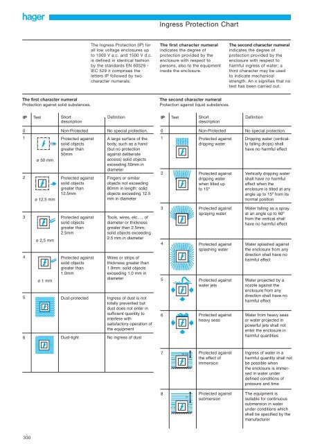
<strong>Ingress</strong> <strong>Protection</strong> <strong>Chart</strong><br />
The <strong>Ingress</strong> <strong>Protection</strong> (IP) for<br />
all low voltage enclosures up<br />
to 1000 V a.c. and 1500 V d.c.<br />
is defined in identical fashion<br />
by the standards EN 60529 -<br />
IEC 529 it comprises the<br />
letters IP followed by two<br />
character numerals:<br />
The first character numeral<br />
indicates the degree of<br />
protection provided by the<br />
enclosure with respect to<br />
persons, also to the equipment<br />
inside the enclosure.<br />
The second character numeral<br />
indicates the degree of<br />
protection provided by the<br />
enclosure with respect to<br />
harmful ingress of water; a<br />
third character may be used<br />
to indicate mechanical<br />
strength. An x signifies that no<br />
test has been carried out.<br />
The first character numeral<br />
<strong>Protection</strong> against solid substances.<br />
The second character numeral<br />
<strong>Protection</strong> against liquid substances.<br />
IP<br />
Test<br />
Short<br />
description<br />
Definition<br />
IP<br />
Test<br />
Short<br />
description<br />
Definition<br />
0<br />
Non-Protected<br />
No special protection.<br />
0<br />
Non-Protected<br />
No special protection.<br />
1<br />
2<br />
ø 50 mm<br />
ø 12.5 mm<br />
Protected against<br />
solid objects<br />
greater than<br />
50mm<br />
Protected against<br />
solid objects<br />
greater than<br />
12.5mm<br />
A large surface of the<br />
body, such as a hand<br />
(but no protection<br />
against deliberate<br />
access) solid objects<br />
exceeding 50mm in<br />
diameter<br />
Fingers or similar<br />
objects not exceeding<br />
80mm in length; solid<br />
objects exceeding 12.5<br />
mm in diameter<br />
1<br />
2<br />
Protected against<br />
dripping water<br />
Protected against<br />
dripping water<br />
when tilted up<br />
to 15º<br />
Dripping water (vertically<br />
falling drops) shall<br />
have no harmful effect<br />
Vertically dripping water<br />
shall have no harmful<br />
effect when the<br />
enclosure is tilted at any<br />
angle up to 15º from its<br />
normal position<br />
3<br />
4<br />
5<br />
6<br />
ø 2,5 mm<br />
ø 1 mm<br />
Protected against<br />
solid objects<br />
greater than<br />
2.5mm<br />
Protected against<br />
solid objects<br />
greater than<br />
1.0mm<br />
Dust-protected<br />
Dust-tight<br />
Tools, wires, etc...., of<br />
diameter or thickness<br />
greater than 2.5mm;<br />
solid objects exceeding<br />
2.5 mm in diameter<br />
Wires or strips of<br />
thickness greater than<br />
1.0mm; solid objects<br />
exceeding 1.0 mm in<br />
diameter<br />
<strong>Ingress</strong> of dust is not<br />
totally prevented but<br />
dust does not enter in<br />
sufficient quantity to<br />
interfere with<br />
satisfactory operation of<br />
the equipment<br />
No ingress of dust<br />
3<br />
4<br />
5<br />
6<br />
Protected against<br />
spraying water<br />
Protected against<br />
splashing water<br />
Protected against<br />
water jets<br />
Protected against<br />
heavy seas<br />
Water falling as a spray<br />
at an angle up to 60º<br />
from the vertical shall<br />
have no harmful effect<br />
Water splashed against<br />
the enclosure from any<br />
direction shall have no<br />
harmful effect<br />
Water projected by a<br />
nozzle against the<br />
enclosure from any<br />
direction shall have no<br />
harmful effect<br />
Water from heavy seas<br />
or water projected in<br />
powerful jets shall not<br />
enter the enclosure in<br />
harmful quantities<br />
7 15 cm Protected against<br />
the effect of<br />
immersion<br />
<strong>Ingress</strong> of water in a<br />
harmful quantity shall not<br />
be possible when<br />
the enclosure is immersed<br />
in water under<br />
defined conditions of<br />
pressure and time<br />
8<br />
m<br />
Protected against<br />
submersion<br />
The equipment is<br />
suitable for continuous<br />
submersion in water<br />
under conditions which<br />
shall be specified by the<br />
manufacturer<br />
330
Type Tested Assemblies<br />
Consumer Units & Distribution Boards<br />
As you might expect, consideration has been given to the design<br />
of the enclosure to accommodate the range of MCB and RCCB<br />
devices which are suitable for use in domestic or similar installations,<br />
or generally in installations where unskilled persons have<br />
access to their use. This, describes the European Norm covering<br />
the requirements of LV Distribution Boards suitable for this application.<br />
The full title is:<br />
EN 60439-3<br />
Specification for low voltage switchgear and control switchgear<br />
assemblies. Part 3. Particular requirements for low-voltage<br />
switchgear and control gear assemblies intended to be installed<br />
in places where unskilled persons have access to their use -<br />
Distribution boards<br />
This standard covers the supplementary requirements for<br />
enclosure distribution boards suitable for indoor use containing<br />
protective devices and intended for use either in domestic<br />
applications or in other places where unskilled persons have<br />
access for their use. Control and/or signalling devices may also<br />
be included.<br />
They are for use on ac, with a nominal voltage to earth not<br />
exceeding 300V. The outgoing circuits contain short circuit<br />
protection devices, each having a rated current not exceeding<br />
125A with a total incoming load current not exceeding 250A.<br />
Customer Distribution Boards which are generally known in<br />
Ireland as Consumer Units are also included in this Standard.<br />
The additional test requirements are set out in annex ZA which<br />
calls for the assembly to withstand a short-circuit fault of 16kA<br />
when protected by a 100A specified fuse.<br />
By definition a customer distribution board or consumer unit is<br />
an integrated assembly, for the control and distribution of electrical<br />
energy, principally in domestic installations, incorporating<br />
manual means of double pole isolation in the incoming circuits,<br />
and are designed for use exclusively with one or more of the<br />
following outgoing circuit protective devices: fuses, MCB’s and<br />
RCBO’s.<br />
The units may also incorporate RCCB’s. Polarity must be<br />
observed throughout and the consumer unit is type tested when<br />
energised through a 100A type II fuse complying with BS1361.<br />
The rated current of a consumer unit is determined by the rated<br />
current of the incoming protective device, usually 63A, 80A or<br />
100A, the rated current of the incoming device(s) is limited to<br />
100A.<br />
As there are no diversity factors applied to consumer units, the<br />
incoming circuit and the bus-bar system must be able to carry<br />
their full rated current without exceeding the temperature rise<br />
limits.<br />
Panelboards<br />
The idea of group mounting MCCBs or MCBs on to a vertical<br />
three phase bus-bar system came from North America during<br />
the 1960s, where it had been used very effectively for a number<br />
of years. The design takes advantage of the modular dimensions<br />
of the circuit breakers which, together with the simple bus-bar<br />
system, proved to be very economical and safe. The basic<br />
design philosophy behind the panelboard is to provide a three<br />
phase distribution board capable of accommodating MCCBs,<br />
which is simple to specify, manufacture and install, and can be<br />
made available “off the shelf” or on a very short delivery cycle.<br />
Generally installed for commercial and light industrial application<br />
the panelboard is, however, used in many different types of<br />
applications.<br />
Panelboards are covered by the European Norm for Low-voltage<br />
Switchgear and Control Gear Assemblies EN 60439 Part 1,<br />
which is the specification for type-tested and partially typetested<br />
assemblies (general requirements).<br />
Panelboards are usually type-tested assemblies but, unlike<br />
consumer units and distribution boards, they do not, as yet,<br />
have their own particular standard, so care must be taken in<br />
their selection and application. It is important that the system<br />
designer understands, and is able to use, the technical information<br />
that the manufacturer is required to publish regarding the<br />
panelboard. Most of the information is straightforward and<br />
presents little problem, except perhaps for internal separation<br />
(Form numbers), degree of protection (IP rating) and short-circuit<br />
withstand strength.<br />
Internal Separation<br />
The internal separation of assemblies is described EN 60439 and<br />
is concerned with three requirements which can be met by the<br />
suitable arrangement of barriers or partitions.<br />
• <strong>Protection</strong> against contact with live parts belonging to adjacent<br />
functional units.<br />
• Limitation of the possibility of initiating and spreading of arcing<br />
faults.<br />
• Prevention of the passage of solid foreign bodies from one unit<br />
of an assembly to an adjacent unit.<br />
Form numbers are given to some typical forms of<br />
separation -<br />
Form 1 - No separation<br />
Form 2 - Separation of bus-bars from the functional units<br />
Form 3 - Separation of bus-bars from the functional units and<br />
separation of all functional units from one another, but<br />
not their outgoing terminals.<br />
Form 4 - Separation of bus-bars from the functional units and<br />
separation of all functional units from one another<br />
including their outgoing terminals.<br />
Invicta<br />
331
Type Tested Assemblies<br />
Degree of <strong>Protection</strong> of Enclosures<br />
The degree of protection provided by an enclosure is<br />
indicated by the IP code in the following way -<br />
Code Letters IP 3 1 C<br />
(International <strong>Protection</strong>)<br />
First Numeral<br />
(Resistance to solid objects 0-6)<br />
Second Numeral<br />
(Resistance to water 0-8)<br />
Additional Letter (optional)<br />
(Limited entry of solid objects)<br />
For example, an enclosure with an index IP20 would provide<br />
protection against solid bodies greater than 12mm but offer no<br />
protection against water; however an index IP31 would provide<br />
protection against solid bodies greater than 2.5mm and in addition<br />
against vertically dripping water.<br />
Sometimes the letter ‘X’ is used in place of the first or<br />
second numeral to indicate that tests have not been made or are<br />
not considered relevant. For example IP4X provides protection<br />
against a 1mm probe but has not been tested for the ingress of<br />
water. Refer to page 330 for ingress protection chart.<br />
Invicta 125 Panelboard<br />
Enclosure - Degree of protection (door closed) IP3X<br />
Internal Separation Form 3<br />
Bus-bar rated current<br />
400A<br />
Bus-bar rated short-time withstand current 35kA for 1s<br />
direct connected<br />
(unconditional)<br />
Incoming - Main Terminals 400A<br />
Non-Auto MCCB 400A<br />
MCCB<br />
400A<br />
Outgoing - H125 MCCBs 16 to 125A<br />
4 way<br />
6 way<br />
8 way<br />
12 way<br />
Maximum Prospective Short-circuit level<br />
at point of application with<br />
• Incomer - main terminals - outgoing H125<br />
• Incomer - non-auto MCCB - outgoing H125<br />
• Incomer - H400 MCCB - outgoing H125<br />
Table 1<br />
15kA<br />
15kA<br />
25kA<br />
Short-Circuit Withstand<br />
The European Normrequires the manufacturer to state the<br />
following:<br />
For a panelboard with an incoming MCCB -<br />
• The maximum allowable value of prospective shortcircuit current<br />
at the terminals of the incoming MCCB.<br />
For a panelboard where a short-circuit protective device is not<br />
incorporated in the incoming unit (Main Terminals) -<br />
• The rated short-time withstand current<br />
• The rated peak withstand current<br />
• The withstand time period if different from one second.<br />
All Invicta panel boards have been independently tested at a UK<br />
ASTA approved test laboratory.<br />
To assist in the selection of the correct panelboard, suitable for<br />
use on systems having prospective fault levels ranging from 15<br />
to 50kA, <strong>Hager</strong> have prepared the following simple charts.<br />
Invicta 250 Panelboard<br />
Enclosure - Degree of protection (door closed) IP3X<br />
Internal Separation Form 3<br />
Bus-bar rated current<br />
800A<br />
Bus-bar rated short-time withstand current 35kA for 1s<br />
Rated conditional short circuit current<br />
40kA - direct<br />
connected<br />
with 250A<br />
MCCB<br />
outgoing<br />
Incoming - Main Terminals 800A<br />
Non-Auto MCCB 800A<br />
MCCB<br />
800A<br />
Outgoing - H125 MCCBs 16 to 125A<br />
H250 MCCBs 160 to 250A<br />
6 way<br />
8 way<br />
12 way<br />
18 way<br />
Maximum Prospective Short-circuit level at point of<br />
application with<br />
• Incomer - main terminals - outgoing H125<br />
• Incomer - main terminals - outgoing only H250<br />
• Incomer - non-auto MCCB - outgoing H125<br />
• Incomer - non-auto MCCB - outgoing only H250<br />
• Incomer - H400 MCCB - outgoing H125<br />
• Incomer - H400 MCCB - outgoing only H250<br />
• Incomer - H800 MCCB - outgoing only H250<br />
15kA<br />
40kA<br />
15kA<br />
40kA<br />
25kA<br />
35kA<br />
50kA<br />
332
Fuse Combination Switches<br />
Cat Ref. Description Height Width Depth<br />
JFB202U 20A SPSN 250 200 150<br />
JFB203U 32A SPSN 250 200 150<br />
JFB302U 20A TPN 250 200 150<br />
JFB303U 32A TPN 250 200 150<br />
JFB402U 20A TPSN 250 200 150<br />
JFB403U 32A TPSN 250 200 150<br />
JFD206U 63A SPSN 325 300 150<br />
JFD306U 63A TPN 325 300 150<br />
JFD406U 63A TPSN 325 300 150<br />
JFE210U 100A SPSN 400 375 200<br />
JFE310U 100A TPN 400 375 200<br />
JFE410U 100A TPSN 400 375 200<br />
JFG312U 125A TPN 500 375 200<br />
JFG412U 125A TPSN 500 375 200<br />
JFG316U 160A TPN 500 375 200<br />
JFG416U 160A TPSN 500 375 200<br />
JFG320U 200A TPN 500 375 200<br />
JFG420U 200A TPSN 500 375 200<br />
JFG325U 250A TPN 500 375 200<br />
JFG425U 250A TPSN 500 375 200<br />
JFH331U 315A TPN 650 500 300<br />
JFH431U 315A TPSN 650 500 300<br />
JFH340U 400A TPN 650 500 300<br />
JFH440U 400A TPSN 650 500 300<br />
JFI363U 630A TPN 800 600 350<br />
JFI463U 630A TPSN 800 600 350<br />
JFI380U 800A TPN 800 600 350<br />
JFI480U 800A TPSN 800 600 350<br />
All dimensions are in mm and exclude the handle.<br />
Add 70mm to the depth to allow for the handle (110mm for 630 /<br />
800A)<br />
Table 4<br />
Cable Extension Boxes for Fuse Combination Switches<br />
Cat Ref. Rating Height Width Depth<br />
JZA701 125 / 250A 200 375 200<br />
JZA702 315 / 400A 250 500 300<br />
JZA703 630 / 800A 300 600 350<br />
Invicta<br />
333
Fuse Combination Units<br />
Thermal current Ith (40ºC) 20A 32A 63A 100A 125A 160A 200A 250A 315A 400A 630A* 800A*<br />
Fuse size: BS A1 A1 A2-A3 A4 B1-B2 B1-B2 B1-B2 B1-B3 B1-B3 B1-B4 C1-C2 C1-C3<br />
Rated insulated voltage<br />
Ui (V) 800 800 800 800 800 800 800 800 800 800 1000 1000<br />
Impulse voltages Uimp 8000 8000 8000 8000 8000 8000 8000 8000 8000 8000 12000 12000<br />
Operational current Ie (A) A B A B A B A B A B A B A B A B A B A B A B A B<br />
415V ac AC-22A/AC-23B 20 20 32 32 63 63 100 100 125 125 160 160 200 200 250 250 315 315 400 400 630 630 800 800<br />
Motor power (kW)<br />
400V ac 9 15 30 51 63 80 100 ** 160 160 220 220 355 355 **<br />
Reactive power 400V ac<br />
(kVAR) 15 45 25 45 55 60 75 ** 125 150 2x125 **<br />
Overload capacity<br />
Short-circuit with fuses<br />
(kA Rms) 50 50 50 50 50 50 50 50 50 50 50 50<br />
Fuse rating (A) 20 32 63 100 125 160 200 250 315 400 630 800<br />
BS88<br />
Making & breaking<br />
Characteristics<br />
Breaking capacity 160 256 500 800 1000 1280 1600 2000 2520 3200 ** **<br />
400V AC-23B (A Rms)<br />
Making capacity 200 320 630 1000 1250 1600 2000 2500 3150 4000 ** **<br />
400V AC-23B (A Rms)<br />
Withstand<br />
mechanical 20,000 20,000 10,000 10,000 10,000 10,000 10,000 10,000 10,000 10,000 8000 8000<br />
(Number of operations)<br />
Electrical - - - - - - - ** - - - - **<br />
(Number of operations)<br />
Tightening torque 2 2 6 9 9 9 20 20 20 40 40<br />
Connection<br />
Minimum Cu<br />
Cable section (mm 2 ) 2.5 2.5 10 25 35 50 70 70 185 185 2x150 2x150<br />
Maximum Cu<br />
Cable section (mm 2 ) 16 16 25 95 95 95 240 240 240 240 2x300 2x300<br />
Fuse types NIT20 NIT32 TIS63 TCP100 TF125 TF160 TF200 TKF250 TKF315 TMF400 TTM630 TLM800<br />
* 630A AC22B making and breaking<br />
* 800A<br />
** Please call our technical support helpine for these details<br />
Table 5<br />
334
Switch Disconnectors<br />
Switch Disconnectors<br />
Cat Ref. Description Height Width Depth<br />
JAB302 20A TPN 250 200 150<br />
JAB303 32A TPN 250 200 150<br />
JAB306 63A TPN 250 200 150<br />
JAB310 100A TPN 250 200 150<br />
JAC312 125A TPN 300 250 150<br />
JAC316 160A TPN 300 250 150<br />
JAE320 200A TPN 400 375 200<br />
JAE325 250A TPN 400 375 200<br />
JAG331 315A TPN 500 375 200<br />
JAG340 400A TPN 500 375 200<br />
JAH363 630A TPN 650 500 300<br />
JAH380 800A TPN 650 500 300<br />
JAB402 20A TPSN 250 200 150<br />
JAB403 32A TPSN 250 200 150<br />
JAB406 63A TPSN 250 200 150<br />
JAB410 100A TPSN 250 200 150<br />
JAC412 125A TPSN 300 250 150<br />
JAC416 160A TPSN 300 250 150<br />
JAE420 200A TPSN 400 375 200<br />
JAE425 250A TPSN 400 375 200<br />
JAG431 315A TPSN 500 375 200<br />
JAG440 400A TPSN 500 375 200<br />
JAH463 630A TPSN 650 500 300<br />
JAH480 800A TPSN 650 500 300<br />
Table 7<br />
Cable Extension Boxes for Switch Disconnectors<br />
Cat Ref. Rating Height Width Depth<br />
JZA700 125 / 160A 200 250 200<br />
JZA701 315 / 400 200 375 300<br />
JZA702 630 / 800 250 500 300<br />
All dimensions are in mm and exclude the handle.<br />
Add 70mm to the depth to allow for the handle<br />
Invicta<br />
335
Switch Disconnectors<br />
Enlosed thermal current lthe 20 32 63 100 125 160 200 250 315 400 630 800<br />
Rated insulation voltage Ui (V) 800 800 800 800 800 800 800 800 800 800 1000 1000<br />
Rated Thermal current Ithe (A) 20 32 63 100 125 160 200 250 315 400 630 800<br />
Rated operational Current<br />
AC21A 500VAC 20 32 63 100 125 160 160 250 250 250 630 800<br />
AC22A 20 32 63 100 125 125 125 250 250 250 500 800<br />
AC21A 690VAC 20 32 63 100 125 160 160 200 200 200 500 800<br />
AC22A 20 32 63 100 125 125 125 125 125 125 315 800<br />
Overload capacity<br />
Icw Rated Short time withstand value (kA/s) 1.26 1.26 1.5 1.5 7 7 7 9 9 9 13 26<br />
R.M.S. value (kA) 0.16 0.256 0.504 0.64 1 1.28 1.28 2 2 2 5.04 6.4<br />
Peak withstand value (kA) - - - - 20 20 18 30 23 23 45 55<br />
Rated short circuit making capacity (kA) 1.8 1.8 2.1 2.1 11.9 11.9 11.9 15.3 15.3 15.3 26 54.6<br />
Rated impulse withstand voltage Uimp (kV) 8 8 8 8 8 8 8 8 8 8 12 12<br />
Mechanical endurance Number of 100,000 100,000 100,000 100,000 10,000 10,000 10,000 10,000 10,000 5,000 5,000 5,000<br />
operations<br />
Maximum cable size mm 2 16 16 50 50 50 95 95 150 185 240 2x300 2x300<br />
Tightening torque 2 2 4 4 9 9 9 20 20 20 20 -<br />
Table 9<br />
336
IP65 Enclosed Isolating Switch<br />
Cat Ref. Description Height Width Depth<br />
JG00S 10A TPN 136 100 74<br />
JG01S 16A TPN 136 100 105<br />
JG02S 25A TPN 136 100 105<br />
JG03S 40A TPN 201 136 105<br />
JG04S 63A TPN 201 136 118<br />
JG05S 80A TPN 201 136 118<br />
Table 6<br />
All dimensions are in mm and exclude the handle.<br />
Add 27mm to the depth to allow for the handle on 10-25A products.<br />
Add 32mm to the depth to allow for the handle on 40-80A products.<br />
Enclosed thermal current Ithe 16 25 40 63 80/100<br />
Rated insulation voltage Ui (V) 690 690 690 690 690<br />
Rated thermal current Ithe (A) 25 40 63 80 100<br />
Rated operational current<br />
AC-21 400V Ie (A) 25 40 63 80 100<br />
AC-22 230V 16 25 40 63 100<br />
AC-22 400V cos phi 0.65 16 20 32 63 100<br />
AC-23 230V 16 20 32 63 100<br />
AC-23 400V cos phi 0.35 16 15 25 40 63<br />
Rated operational power<br />
AC-23 230V (kW) 4 5.5 7.5 11 15<br />
AC-23 400V 7.5 11 15 22 30<br />
Rated fused short circuit current<br />
Back-up fuse (A) 63 63 63 80 100<br />
R.M.S. value Ik (kA) 50 50 50 50 50<br />
Peak value (kA) 5.4 6.6 7.2 8.3 8.7<br />
Rated short circuit making capacity (Icm) (kA) 5.4 6.6 7.2 8.3 8.7<br />
Rated short-time withstand current (Icm) (kA) 0.9 1 1.1 1.6 1.7<br />
Rated breaking capacity Icn (A) AC-23<br />
400V cos phi 0.35 250 270 320 480 504<br />
Electrical endurance (number of operations) 3000 3000 3000 3000 3000<br />
Mechanical endurance (number of operations) 50000 50000 50000 50000 50000<br />
Terminals mm 2 1.5-16 1.5-16 1.5-16 2.5-35 2.3-35<br />
Max. thermal torque (Nm) 1.8 1.8 1.8 2.5 2.5<br />
Table 9a<br />
Invicta<br />
337
Utilisation Categories and Definitions<br />
Fuse - Combination Units - EN 60947-3<br />
Many people are attracted to fuse-combination units by their<br />
simplicity in application and their reliability in operation. They are<br />
particularly useful for use on very high prospective fault level<br />
systems where the high energy limiting characteristic of the HRC<br />
fuse can be effectively utilised. In the past fuse-combination<br />
units came in two forms -<br />
Switch-Fuse<br />
Fuse-Switch<br />
A switch in which one or more<br />
poles have a fuse in series.<br />
A switch in which one or more<br />
poles have a fuse carrier/link which<br />
forms the moving contact.<br />
The definitions of these two basic types of fuse combination<br />
units have now been extended to include units suitable for<br />
making, breaking and isolation and units which are only suitable<br />
for providing isolation for maintenance work.<br />
Definition Symbol Function<br />
Switch fuse<br />
Making and Breaking<br />
current<br />
Disconnector Fuse<br />
Isolating<br />
Utilisation categories<br />
Utilisation categories are not new but they are important because<br />
they help the designer or specifier identify the correct unit for a<br />
particular application.<br />
The designation of the utilisation category is made up of three<br />
parts:<br />
(1) The prefix ac or dc, which indicates the nature of the current.<br />
(2) The two digit number, which indicates the type of application<br />
the unit is suitable for -<br />
20 Connecting and disconnecting under no-load.<br />
21 Switching of resistive loads.<br />
22 Switching of mixed resistive and inductive loads.<br />
23 Switching of highly inductive loads.<br />
(3) The suffix A or B, which indicates whether the unit is suitable<br />
for frequent or infrequent operation.<br />
A - Frequent operation<br />
B - infrequent operation.<br />
For example a fuse-combination unit feeding a 400V ac circuit of<br />
mixed resistive and inductive loads which would need to be<br />
operated frequently would require a minimum utilisation category<br />
of AC-22A.<br />
If the load was highly inductive, i.e. motor loads, then the minimum<br />
utilisation category would be AC-23A.<br />
Generally, category AC-23 does not cover the switching of<br />
capacitors. Usually this is the subject of agreement between<br />
manufacturer and user.<br />
Switch Disconnector<br />
Fuse<br />
Fuse Swtich<br />
Fuse Disconnector<br />
Fuse Switch<br />
Disconnector<br />
Table 10<br />
Making, Breaking and<br />
Isolating<br />
Making and Breaking<br />
Current<br />
Isolating<br />
Making, Breaking and<br />
Isolating<br />
Motor Power Circuit <strong>Protection</strong><br />
Fuse-combination units can be used very effectively for motor<br />
power circuit protection, the energy limiting HRC fuse offering<br />
very good protection to its associated starter. Category AC-23A<br />
should be specified for this duty. Special motor circuit protection<br />
fuse links are available which eliminate the need to fit a larger<br />
bodied fuse just to take care of the starting current of the motor.<br />
The protection of motor power circuits should not be confused<br />
with the direct switching of a single motor. If a fuse-combination<br />
unit is required to perform this function then it must comply with<br />
the requirements of Appendix A of EN 60947-3 which makes<br />
provision for different utilisation categories for this application.<br />
However, in order to keep the selection of fuse-combination<br />
units as simple as possible, <strong>Hager</strong> offer a range of high performance<br />
double break switch-fuses, which also satisfy the isolating<br />
requirement of the European standard. These are correctly<br />
shown as and defined as a Fuse Combination Switch.<br />
Switch disconnectors - EN 60947-3. A range of switch<br />
disconnectors (isolators) are available for use on lower current<br />
ratings from 20A to 125A, these switches are rated at AC-22 and<br />
provide a cost effective alternative to the fuse combination<br />
switch especially where the utilisation category AC-23 is not<br />
required. ie; mixed resistive and inductive loads. These may be<br />
used at AC-23 providing they are derated in accordance with<br />
Table 9 page 336.<br />
338
Enclosed MCCBs<br />
- Dimensions<br />
Cat Ref. Description L N Height Width Depth<br />
JG25M 63A SPN 70mm M8 420 267 83<br />
JG26M 63A TPN 70mm M8 420 267 83<br />
JG27M 63A 4P 70mm M8 420 267 83<br />
JG27R 63A 4P + RCCB 70mm M8 420 369 83<br />
JG28M 100A SPN 70mm M8 420 267 83<br />
JG29M 100A TPN 70mm M8 420 267 83<br />
JG30M 100A 4P 70mm M8 420 267 83<br />
JG31M 125A SPN 70mm M8 420 267 83<br />
JG32M 125A TPN 70mm M8 420 267 83<br />
JG33M 125A 4P 70mm M8 420 267 83<br />
JG33R 125A 4P + RCCB 70mm M8 420 369 83<br />
JG34S 125A TPN non auto MCCB 70mm M8 420 267 83<br />
JG35S 125A 4P non auto MCCB 70mm M8 420 267 83<br />
JG36M 160A TPN 120mm M10 660 334 97<br />
JG37M 160A 4P 120mm M10 660 334 97<br />
JG37R 160A 4P + RCCB 120mm M10 768 334 97<br />
JG40M 250A TPN 120mm M10 660 334 97<br />
JG41M 250A 4P 120mm M10 660 334 97<br />
JG41R 250A 4P + RCCB 120mm M10 768 334 97<br />
JG42S 250A TPN non auto MCCB 120mm M10 660 334 97<br />
JG43S 250A 4P non auto MCCB 120mm M10 660 334 97<br />
JG44M 400A TPN 240mm M10 870 384 117<br />
JG45M 400A 4P 240mm M10 870 384 117<br />
JG45R 400A 4P + RCCB 240mm M10 1000 384 117<br />
JG46S 400A TPN non auto MCCB 240mm M10 870 384 117<br />
JG47S 400A 4P non auto MCCB 240mm M10 870 384 117<br />
JG48M 630A TPN 2x240mm M10 1130 509 157<br />
JG49M 630A 4P 2x240mm M10 1130 509 157<br />
JG50S 630A TPN non auto MCCB 2x240mm M10 1130 509 157<br />
JG51S 630A 4P non auto MCCB 2x240mm M10 1130 509 157<br />
All sizes are in mm<br />
Table 3<br />
Invicta<br />
339
Invicta Enclosures<br />
1 row boxes 1-5 modules<br />
This range is ideally suited for<br />
the installation of individual<br />
modular devices. (RCCBs,<br />
MCBs, RCBO’s switch disconnectors<br />
etc).<br />
The range is available without<br />
door, with plain door or with<br />
glazed door.<br />
Where larger cables need to<br />
be accommodated for switch<br />
disconnectors etc extra cabling<br />
space is provided in the<br />
extended height versions.<br />
All boxes from 2-5 modules<br />
are fitted with an earth bar as<br />
standard and for those with<br />
doors the catch can be replaced<br />
with the optional key<br />
locking facility.<br />
Enclosures 8-66 modules<br />
One, two or three row<br />
enclosures, fitted with DIN<br />
rails to accept any combination<br />
of <strong>Hager</strong> modular devices<br />
from the simplest switch and<br />
MCB arrangements to the<br />
more sophisticated control<br />
and protection system.<br />
These enclosures feature:<br />
• Ample wiring space<br />
• Full complement of earth<br />
and neutral bars fitted as<br />
standard<br />
• Significant knockout<br />
provision<br />
• Plain or glazed doors<br />
• Optional key lock<br />
For dimensional information<br />
see 342<br />
Description Cat Ref. Cat Ref. Cat Ref.<br />
without door plain door glazed door<br />
IU41<br />
1 row 1 ❚ suitable for 1 module RCBO<br />
1 row 2 ❚<br />
1 row 2 ❚ extended height<br />
1 row 3 ❚<br />
1 row 4 ❚<br />
1 row 4 ❚ extended height<br />
1 row 5 ❚ extended height<br />
4 mod metal unit 1 x 100A Isolator, AC22A<br />
Connection capacity:<br />
50mm 2 rigid conductor<br />
35mm 2 flexible conductor<br />
1 x 63A Fuse<br />
4 mod metal unit 1 x 100A Isolator, AC22A<br />
Connection capacity:<br />
50mm 2 rigid conductor<br />
35mm 2 flexible conductor<br />
1 x 100A Fuse<br />
IU41<br />
IU2 IU2/D IU2/GD<br />
IU42*<br />
*IU42/D<br />
IU3<br />
IU3/D<br />
IU4<br />
IU4/D<br />
IU44* *IU44/D *IU44/GD<br />
IU45*<br />
IU4-16<br />
IU44-11<br />
IU41-11<br />
JK016G<br />
Note: Recommended maximum cable capacity<br />
* extended height = 35mm 2<br />
all other references = 6mm 2<br />
1 row 8 ❚ with knockouts<br />
1 row 12 ❚ with knockouts<br />
1 row 16 ❚ with knockouts<br />
1 row 22 ❚ with knockouts<br />
JK008<br />
JK012<br />
JK016<br />
JK022<br />
JK008G<br />
JK012G<br />
JK016G<br />
JK022G<br />
2 row 24 ❚ (2 x 12) with knockouts<br />
2 row 32 ❚ (2 x 16) with knockouts<br />
2 row 44 ❚ (2 x 22) with knockouts<br />
JK024<br />
JK032<br />
JK044<br />
JK024G<br />
JK032G<br />
JK044G<br />
3 row 66 ❚ (3 x 22) with knockouts JK066 JK066G<br />
340
Invicta Enclosures<br />
Versatile modular design<br />
The modern design of Invicta<br />
enclosures, allows great<br />
versatility in circuit design.<br />
This coupled with the extensive<br />
range of modular circuit<br />
protection control and energy<br />
management devices available<br />
from <strong>Hager</strong> offers the circuit<br />
designer the facility to match<br />
the distribution board precisely<br />
to the installation requirements<br />
without compromise.<br />
Description<br />
Cat. Ref.<br />
Accessories<br />
keylock with 2 keys suitable for all enclosures<br />
fitted with door - IU enclosure<br />
JK enclosure<br />
IKL1<br />
JK222A<br />
JK222A<br />
100A 2 pole switch disconnector<br />
63A 30mA 2 pole RCCB<br />
100A 30mA 2 pole RCCB<br />
100A single module terminal block (MCB profile)<br />
SB299<br />
CDC263U<br />
CD284U<br />
KR50U<br />
Note: For further options please consult <strong>Hager</strong><br />
CDC263U<br />
Invicta<br />
341
Invicta enclosures - IP30<br />
- Dimensions<br />
Cat Ref Height Width Depth Connection Knockouts<br />
IU41 152mm 50mm 61.5mm earth only 2 x 20mm<br />
IU2, IU3 152mm 80mm 61.5mm earth only 2 x 20mm<br />
IU2/D<br />
IU2/GD 152mm 80mm 87.5mm earth only 2 x 20mm<br />
IU3/D<br />
IU4 187mm 115mm 61.5mm earth only 2 x 25mm<br />
IU4/D 187mm 115mm 87.5mm earth only 2 x 25mm<br />
IU44 312mm 125mm 73.5mm earth only none<br />
IU45<br />
IU44/D 312mm 125mm 99.5mm earth only none<br />
IU44/GD<br />
IU42 312mm 80mm 61.5mm earth only 2 x 20mm<br />
IU42/D 312mm 80mm 100mm earth only 2 x 20mm<br />
IU44-11 312mm 125mm 99.5mm earth only none<br />
IU4-16 187mm 115mm 61.5mm earth only 2 x 25mm<br />
342
Insulated busbars - prong<br />
Designation Section In Width Pack Cat.<br />
in I qty Ref.<br />
1 pole, 1I step<br />
brown insulation (phase) 10 63A 13I 50 KB 063P<br />
KB 063P<br />
KB 163N<br />
KB 190C<br />
blue insulation (neutral) 10 63A 13I 50 KB 163N<br />
without insulation 10 63A 13I 50 KB 163I<br />
insulated 20 100A 57I 10 KB 190B<br />
20 100A 24I 10 KB 190C<br />
2 poles, 2I step<br />
insulated 10 63A 12I 10 KB 263A<br />
KB 263A<br />
10 63A 24I 10 KB 263C<br />
16 80A 56I 10 KB 280B<br />
3 poles, 3I step<br />
insulated 10 63A 12I 10 KB 363A<br />
KB 363A<br />
10 63A 57I 20 KB 363B<br />
10 63A 24I 10 KB 363C<br />
16 80A 12I 25 KB 380A<br />
16 80A 57I 10 KB 380B<br />
4 poles, 4I step<br />
insulated 10 63A 12I 10 KB 463A<br />
KB 463A<br />
10 63A 24I 10 KB 463C<br />
16 80A 12I 25 KB 480A<br />
16 80A 56I 10 KB 480B<br />
Cable connectors<br />
connection from top In 63A for cables : 25 mm≈ 10 KF 81A<br />
for cables : 2 x 16 mm≈ 10 KF 82A<br />
connection from side In 63A for cables : 25 mm≈ 10 KF 83A<br />
KF 81A<br />
KF 82A<br />
End cap cover<br />
for single pole busbars KB 163P 1 set KZ 021<br />
and KB 163N<br />
KF 83A<br />
KZ 021<br />
KZ 023<br />
for double pole busbars, 10mm≈ 1 set KZ 022<br />
for triple pole busbars 10 or 16mm≈ 1 set KZ 023<br />
for four pole busbars 10 or 16mm≈ 1 set KZ 024<br />
Connection<br />
Systems<br />
343
Insulated busbars - fork and accessories<br />
Designation section In<br />
Width<br />
in I<br />
Pack<br />
qty<br />
Cat.<br />
Ref.<br />
1 pole, 1 ❚ step 10<br />
63A<br />
12 ❚<br />
100<br />
KD 163A<br />
KD 190B<br />
10<br />
63A<br />
56 ❚<br />
50<br />
KD 163B<br />
16<br />
80A<br />
12 ❚<br />
100<br />
KD 180A<br />
16<br />
80A<br />
56 ❚<br />
50<br />
KD 180B<br />
20<br />
100A<br />
56 ❚<br />
10<br />
KD 190B<br />
2 pole, 2 ❚ step<br />
KDN 263A<br />
insulated 10<br />
63A<br />
12 ❚<br />
10<br />
KDN 263A<br />
10<br />
63A<br />
24 ❚<br />
10<br />
KDN 263C<br />
16<br />
80A<br />
56 ❚<br />
10<br />
KDN 280B<br />
3 pole, 3 ❚ step<br />
KDN 363A<br />
insulated 10<br />
63A<br />
12 ❚<br />
10<br />
KDN 363A<br />
10<br />
63A<br />
57 ❚<br />
20<br />
KDN 363B<br />
10<br />
63A<br />
24 ❚<br />
10<br />
KDN 363C<br />
16<br />
80A<br />
12 ❚<br />
25<br />
KDN 380A<br />
16<br />
80A<br />
57 ❚<br />
10<br />
KDN 380B<br />
4 pole, 4 ❚ step<br />
KDN 463A<br />
insulated 10<br />
63A<br />
12 ❚<br />
10<br />
KDN 463A<br />
10<br />
63A<br />
24 ❚<br />
10<br />
KDN 463C<br />
16<br />
80A<br />
12 ❚<br />
25<br />
KDN 480A<br />
16<br />
80A<br />
56 ❚<br />
10<br />
KDN 480B<br />
Cable connectors<br />
connection from top In 63A<br />
for cables : 25 mm≈<br />
10<br />
KF 81A<br />
KF 81A<br />
KF 82A<br />
connection from side In 63A<br />
for cables : 2 x 16 mm≈<br />
for cables : 25 mm≈<br />
10<br />
10<br />
KF 82A<br />
KF 83A<br />
End cap cover<br />
for double pole busbars, 10mm≈<br />
1 set<br />
KZ 022<br />
KZN 023<br />
for triple pole busbars 10 or 16mm≈<br />
for four pole busbars 10 or 16mm≈<br />
1 set<br />
1 set<br />
KZ 023<br />
KZ 024<br />
344
Brass terminals ≤ 60A<br />
Description<br />
Brass terminals with / without<br />
plastic supports for neutral<br />
and earth connections<br />
Technical data<br />
brass terminals with / without<br />
earth = green / yellow support<br />
phase = beige support<br />
neutral = blue support<br />
in DIN rail with KZ060 rail clip<br />
or flat bar 12x2mm<br />
Connections Terminals with support without support<br />
number + section pack neutral earth phase Pack Cat.<br />
qty. cat. ref. cat.ref. cat. ref. qty. ref.<br />
2x16 + 2x10▫ 50 - - KM 04L 10 K 140<br />
4 connections<br />
length 30mm<br />
KM 04L<br />
4x16 + 4x10▫ 20 - - KM 08L - -<br />
8 connections<br />
length 30mm<br />
KM 08L<br />
3x16 + 4x10▫ 50 KM 07N KM 07E KM 07L 10 K 142<br />
7 connections<br />
length 49mm<br />
KM 07N<br />
5x16 + 5x10▫ 20 KM 10A KM 10B KM 10C 10 K 143<br />
10 connections<br />
length 67mm<br />
5x16 + 6x10▫ 20 KM 11N KM 11E KM 11L 10 K 144<br />
11 connections<br />
length 73mm<br />
KM 10E<br />
2x16 (double drive) + 8x10 20 KM 10N KM 10E KM 10L 10 K 145<br />
10 connections<br />
length 69mm<br />
KM 13N<br />
6x16 +7x10▫ 20 KM 13N KM 13E - 10 K 148<br />
13 connections<br />
length 85mm<br />
KM 11B<br />
1x25 +5x16 + 5x10▫ 20 - KM 11B - 10 K 151<br />
11 connections<br />
length 85mm<br />
KM 25N<br />
1x25 +8x16 + 8x10▫ 20 KM 17N KM 17E - 10 K 156<br />
17 connections<br />
length 121mm<br />
KM 25E<br />
1x25 +11x16 + 13x10▫ 20 KM 25N KM 25E - 10 K 158<br />
25 connections 2 supports<br />
length 169mm<br />
K 151<br />
K 158<br />
1x25 +8x16 + 29x10▫ long length length 242mm 10 K 159<br />
terminals<br />
(without support)<br />
1x25 +16x16 + 61x10▫ fixing on the length 482mm 10 K 160<br />
flat bar<br />
12 x 2 with supports<br />
(see below)<br />
1x25 + 3x16 + 129x10▫ length 992mm 10 K 162<br />
K 159<br />
KZ 012<br />
KZ 060<br />
supports for K140 blue support for neutral 10 KZ 012<br />
to K162 terminals<br />
insulating material green / yellow support for earth 10 KZ 013<br />
M4 x 8 fixing screws<br />
beige supports (see below) 10 KZ 014<br />
Rail clip mounting on DIN rail 50 KZ 060<br />
for fixing terminals on<br />
DIN rail not for : KM 08L<br />
KM 10A, KM 10B, KM 10C,<br />
KM 10N, KM 10E, KM 10L horizontally<br />
345<br />
Connection<br />
Systems
Connection blocks ≤ 125 A<br />
Application :<br />
connection blocks 16▫ to 35▫<br />
to connect incoming cables<br />
and continue live feed.<br />
technical data :<br />
connection :<br />
incoming : 2 x 25▫ or 2 x 35▫<br />
outgoing : 16▫ or 25▫<br />
mounting : fixing on DIN rail<br />
connection blocks include :<br />
one insulated support, brass<br />
connection blocks with<br />
removable antishear plates<br />
to enable the incoming cables<br />
to be connected without cutting.<br />
Designation Characteristics Width in Pack Cat.<br />
17.5mm qty. ref.<br />
Connection blocks 1 pole 2 fi 20 K 018<br />
connection on each pole<br />
incoming : 2 x 25▫<br />
l. 34 x h. 50 x w. 52mm<br />
4 separate outgoing ways : 16▫<br />
2 poles 4 10 K 023<br />
l. 64 x h. 50 x w. 52mm<br />
4 poles 7 5 K 024<br />
K 018<br />
l. 121 x h. 50 x w. 62mm<br />
5 poles 8 fi 5 K 025<br />
l. 150 x h. 50 x w. 62mm<br />
K 025<br />
Connection blocks 1 pole 2 fi 10 K 037<br />
connection :<br />
incoming : 2 x 35▫<br />
l. 37 x h. 30 x w. 47mm<br />
4 separate outgoing ways : 25▫<br />
K 037<br />
346
Distribution and terminal blocks<br />
Designation Characteristics Pack.<br />
qty.<br />
Cat.<br />
ref.<br />
KJ 01B<br />
Terminal blocks<br />
fixing by clip on DIN rail<br />
delivered with :<br />
insulated back plate<br />
transparent protection<br />
front cover<br />
In : by 40°C<br />
In 100A – two poles Icc : 29KA<br />
connectors on each terminal :<br />
incoming : 1x35 flexible,<br />
outgoing : 1x25 + 10x16 flexible<br />
w. 129 (7.5 ❚) x h. 86 x d. 44 mm<br />
In 80A – four poles Icc : 21KA<br />
connectors on each terminal :<br />
incoming : 1x16 flexible,<br />
outgoing : 8x10 flexible<br />
1 KJ 01A<br />
1 KJ 01B<br />
w. 88 (5 ❚) x h. 86 x d. 44 mm<br />
KJ 01C<br />
In 125A – four poles Icc : 29KA<br />
connectors on each terminal :<br />
incoming : 1x35 flexible,<br />
outgoing : 1x25 + 10x16 flexible<br />
1 KJ 01C<br />
w. 129 (7.5 ❚) x h. 86 x d. 44 mm<br />
In 125A – four pole Icc : 29KA<br />
connectors on each terminal :<br />
incoming : 1x35 flexible,<br />
outgoing : 1x25 + 10x16 flexible<br />
1 KJ 02E<br />
KJ 02E<br />
w. 129 (7.5 ❚) x h. 86 x d. 44 mm<br />
connection capacity per block :<br />
125 A : (width 27mm)<br />
incoming : 1x35 + 1x165 ,<br />
outgoing : 6x16 4 KJ 02D<br />
KJ 01D<br />
modular distribution blocks<br />
monobloc, insulated protection<br />
for each phase terminal.<br />
Cover removable with a tool.<br />
In 160A – four poles Icc : 20KA<br />
connectors on each terminal :<br />
incoming : 4x50 flexible,<br />
outgoing : 3x35 , 8x16 flexible<br />
w. 162 (9.5 ❚) x h. 87 x d. 60 mm<br />
(modular shoulder measurement<br />
45mm)<br />
1 KJ 01D<br />
modular Distribution blocks<br />
single pole<br />
monobloc, insulated, grey colour<br />
fixing by clip on DIN rail<br />
connection capacity per block 35 mm 4<br />
KJ 02C<br />
160A (width 35mm)<br />
incoming : 1x70 , outgoing 6x16 <br />
250 A :<br />
incoming : 1x95 45 mm 4<br />
KJ 02A<br />
,<br />
outgoing :2x25 , 5x16 , 4x10 <br />
4 x KJ 02A<br />
400 A :<br />
incoming : 1 x 150 45 mm 4<br />
KJ 02B<br />
,<br />
outgoing:2x25 , 5x16 , 4x10 <br />
Distribution blocks<br />
fitting on DIN rail<br />
for connections :<br />
25 to 95 <br />
35 to 150 25 mm<br />
31 mm<br />
1<br />
1<br />
KR 95P<br />
KR 15P<br />
Connection<br />
Systems<br />
KR 95P<br />
KR 15P<br />
347
Quick Connect Terminals<br />
Quick connect terminals<br />
for the connection of the earth,<br />
neutral and phase.<br />
The distribution blocks are<br />
equipped by terminals without<br />
screw for direct assembling for<br />
cables of 1.5 with 4 mm 2 and of<br />
terminals with cages for the<br />
connection of cables for<br />
sections from 1.5 to 25 mm 2 .<br />
Neutral = blue connector block<br />
Phase = brown connector block<br />
Earth = green/yellow connector<br />
block.<br />
The connector blocks are<br />
clipped on supports of the<br />
enclosures and cabinets.<br />
These connector block supports<br />
exist for the ranges of<br />
enclosures and cabinets Volta,<br />
Vector, Vega and Gamma.<br />
They can also replace one<br />
existing support.<br />
• connector block out<br />
of insulating material,<br />
• IP2x,<br />
• maximum intensity: 63 A<br />
tension of insulation:<br />
Ui = 400 V<br />
• conforms to the standard<br />
EN 60 998<br />
Connections of the distribution blocks :<br />
terminals “q.connect” screw in<br />
1.5 at 4 mm 2 1.5 at 25 mm 2<br />
Pack.<br />
qty<br />
Ref<br />
Neutral Phase Earth PE<br />
5<br />
1<br />
KN 06N<br />
KN 06P<br />
KN 06E<br />
8<br />
2<br />
KN 10N<br />
KN 10P<br />
KN 10E<br />
KN 06P<br />
11<br />
3<br />
KN 14N<br />
KN 14P<br />
KN 14E<br />
14<br />
4<br />
KN 18N<br />
KN 18P<br />
KN 18E<br />
17<br />
5<br />
KN 22N<br />
KN 22P<br />
KN 22E<br />
KN 22N<br />
20<br />
6<br />
KN 26N<br />
KN 26P<br />
KN 26E<br />
KN 26E<br />
Designation Caracteristics Ref.<br />
KN 99P/N/E<br />
Cables for tap-off between 2<br />
Quick Connect Terminals<br />
To connect 2 terminals<br />
each other.<br />
for<br />
Neutral terminals<br />
Phase terminals<br />
Earth terminals<br />
KN 99N<br />
KN 99P<br />
KN 99E<br />
VZ 711<br />
VZ 710<br />
Quick connect for terminal<br />
supports.<br />
The supports are suitable for all<br />
the terminals range (neutral, phase<br />
and earth)<br />
Choice of the support according<br />
to the enclosure range.<br />
for :<br />
- Volta, Vector<br />
Vega flush<br />
- Vega surface<br />
- Gamma<br />
VZ 710<br />
VZ 711<br />
GZ 30A<br />
GZ 30A<br />
Terminals universal support<br />
length : 105 mm<br />
KN 00A<br />
KN 00A<br />
Support fixing on 12x2 mm bars<br />
on horizontal or vertical DIN rail<br />
Pre-cut support to fit with the<br />
terminal size<br />
KN 07N<br />
Entry terminals<br />
For connecting incoming cables<br />
up to 25 mm 2<br />
Ui = 630 V, 90 A<br />
Clip on the terminals support<br />
(VZ 711, VZ 710, GZ 30A et KN<br />
00A)<br />
KN 04N<br />
Neutral terminals : 4 x 25 mm 2<br />
7 x 25 mm 2 KN 07P<br />
7 x 25 mm 2<br />
KN 07N<br />
Phase terminals : 4 x 25 mm 2<br />
KN 04P<br />
KN 04P<br />
348
Terminals<br />
B<br />
A<br />
Terminals dim. dim.<br />
in mm in mm<br />
0.5 at 6 44.5 48.5<br />
1.5 at 50 58 51.5<br />
70 76 79<br />
Connecting<br />
terminals from 0.5 to 70 mm 2<br />
• great resistance to leakage<br />
current KC >600<br />
• mounting on DIN rail<br />
• uniform dimensions<br />
reduce number of accessories<br />
• complies to IEC 60947-1<br />
• good tightening capacity, also<br />
suitable for two conductors<br />
• conductor guilded directly into<br />
terminals connector<br />
• guiding of screwdriver via<br />
embedded screws<br />
• screws run idle when untightening,<br />
very important with<br />
electric screwdrivers<br />
• all parts located in the terminal<br />
fixed<br />
Designation<br />
cable section<br />
(flexible)<br />
(rigid)<br />
In / A<br />
Width<br />
in mm<br />
Ref.<br />
Phase Neutral Earth PE<br />
KX 04F<br />
KX 04H<br />
Phase terminals<br />
grey<br />
Neutral terminals<br />
blue<br />
Earth PE terminals<br />
green / yellow<br />
automatic earthing<br />
of the rail<br />
0.5 - 2.5 <br />
0.5 - 4 <br />
1 - 10 <br />
4 - 16 <br />
16 - 35 0.5 - 4 <br />
0.5 - 6 <br />
1.5 - 16 <br />
4 - 25 <br />
16 - 50 <br />
70 24<br />
32<br />
57<br />
76<br />
125<br />
192<br />
5<br />
6<br />
10<br />
12<br />
16<br />
24<br />
KX 04F KX 04N KX 04H<br />
KX 06F KX 06N KX 06H<br />
KX 16F KX 16N KX 16H<br />
KX 25F KX 25N KX 25H<br />
KX 50F KX 50N KX 50H<br />
KX 70F<br />
KX 04N<br />
Designation Caracteristics Width<br />
in mm<br />
Cover plates<br />
beige,<br />
in insulating material<br />
for the terminals:<br />
KX 04F/N<br />
KX 06F/N<br />
KX 16F/N<br />
KX 25F/N<br />
KX 50F/N<br />
1.5<br />
1.5<br />
2<br />
Ref.<br />
KW 025<br />
KW 026<br />
KW 031<br />
blocking brackets<br />
black,<br />
in insulating material<br />
for all the terminals of 4 with 50_ <br />
for terminal KX 70F<br />
8<br />
10<br />
KW 033<br />
KW 034<br />
KW 033<br />
Junctions between terminals<br />
can be cutted<br />
for 10 terminals:<br />
KX 04F/N<br />
KW 035<br />
KX 06F/N<br />
KW 036<br />
KX 16F/N<br />
KW 037<br />
Circuit indentification labels<br />
box of 12 compartments<br />
(~500),clip themselves on the terminals<br />
KW 001<br />
Connection<br />
Systems<br />
KW 001<br />
349