Catalogue
Catalogue
Catalogue

You also want an ePaper? Increase the reach of your titles
YUMPU automatically turns print PDFs into web optimized ePapers that Google loves.
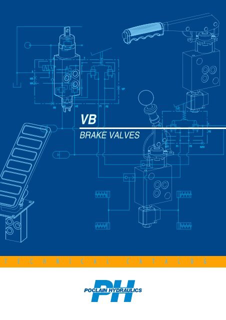
VB<br />
BRAKE VALVES<br />
T E C H N I C A L C A T A L O G
VB Brake valves<br />
POCLAIN HYDRAULICS<br />
HYDRAULIC BRAKE SYSTEM<br />
Tank<br />
Pump<br />
Auxiliaries<br />
Accumulators<br />
store energy for power<br />
off braking.<br />
Emergency / Parking<br />
brake valve<br />
controls the SAHR brake to<br />
provide emergency and parking<br />
brake functions.<br />
Accumulator charging<br />
valve<br />
ensures the pressure is<br />
available in the<br />
accumulator(s) to operate the<br />
brake(s).<br />
SAHR (Spring<br />
Applied, Hydraulics<br />
Release brake)<br />
FRONT<br />
REAR<br />
HASR<br />
(Hydraulic Applied Spring<br />
Release)<br />
Service braking valve<br />
provides HASR brake control to<br />
provide dynamic brake<br />
functions.<br />
2 25/09/2009
POCLAIN HYDRAULICS<br />
CONTENTS<br />
VB Brake Valves<br />
Valves<br />
Page<br />
Emergency / Parking<br />
brake valves<br />
Hydraulic<br />
Electrohydraulic<br />
VB-002 .......5<br />
VB-00E .......11<br />
Service brake valves<br />
Single circuit<br />
VB-010 .......15<br />
Dual circuit<br />
VB-020 .......19<br />
Service brake valves<br />
+ inching<br />
Single circuit<br />
Dual circuit<br />
VB-012 .......23<br />
VB-022 .......27<br />
Steering assist brake valves<br />
VB-0B0.......31<br />
Accumulator charging valves<br />
Single circuit<br />
45 L/min<br />
120 L/min<br />
VB-100 .......35<br />
VB-100 .......39<br />
45 L/min<br />
VB-200 .......43<br />
Dual circuit<br />
120 L/min<br />
VB-200 .......47<br />
Single circuit<br />
• Service brake<br />
• Accumulator charging<br />
45 L/min<br />
120 L/min<br />
VB-110 .......51<br />
VB-110 .......55<br />
Full power brake valves<br />
• Service brake<br />
• Accumulator charging<br />
45 L/min<br />
120 L/min<br />
VB-220 .......59<br />
VB-220 .......63<br />
Dual circuit<br />
• Parking brake<br />
• Service brake<br />
• Accumulator charging<br />
45 L/min<br />
VB-22E .......67<br />
OPTIONS......................................................................................................................................................................71<br />
INSTALLATION............................................................................................................................................................73<br />
25/09/2009 3
VB-002<br />
POCLAIN HYDRAULICS<br />
Methodology :<br />
This document is intended for manufacturers of machines that incorporate Poclain Hydraulics products. It describes the technical characteristics<br />
of Poclain Hydraulics products and specifies installation conditions that will ensure optimum operation.<br />
This document includes important comments concerning safety. They are indicated in the following way:<br />
Safety comment.<br />
This document also includes essential operating instructions for the product and general information. These are indicated in the following way:<br />
Essential instructions.<br />
General information .<br />
Information on the model code.<br />
Weight of component without oil.<br />
Volume of oil.<br />
Units.<br />
Tightening torque.<br />
Screws.<br />
Information intended for Poclain-Hydraulics personnel.<br />
The views in this document are created using metric standards.<br />
The dimensional data is given in mm and in inches (inches are between brackets and italic)<br />
4 25/09/2009
POCLAIN HYDRAULICS<br />
VB-002<br />
VB-002<br />
• Hydraulic<br />
Emergency /<br />
Parking brake<br />
• Single-circuit<br />
Service brake<br />
+ inching<br />
Service<br />
brake<br />
Horizontal<br />
lever<br />
Steering assist<br />
brake<br />
Inching<br />
Vertical<br />
lever<br />
Accumulator<br />
charging<br />
Floor mount<br />
pedal<br />
Lockable<br />
pedal<br />
Full power<br />
brake<br />
Applications<br />
The VB-002 reverse modulator is a mechanically-controlled,<br />
three-way, graduated release pressure reducing valve.<br />
The VB-002 valve is used for the precision dosing of the<br />
output pressure (at X) proportionally to the control stroke. It<br />
is controlled via a lever or pedal. The lever is usually used to<br />
control the parking brake (spring applied hydraulic release<br />
brake).The pedal is usually used for inching control.<br />
Operation<br />
When the control is idle, the output pressure (at X) is limited to the<br />
preset pressure of the valve, irrespective of the supply pressure.<br />
When the lever or pedal is activated, the output pressure (at X) falls in<br />
proportion to the angular position of the control.<br />
•Lever control:<br />
When the lever is in its maximum position (locked), the output<br />
pressure (at X) is zero. The control lever can be unlocked<br />
using the pushbutton (horizontal lever) or the collar (vertical<br />
lever).<br />
•Pedal control:<br />
When the pedal is fully depressed, the output pressure (at X)<br />
is zero.<br />
Options<br />
Installation<br />
25/09/2009 5
VB-002<br />
POCLAIN HYDRAULICS<br />
Overall dimensions of VB-002 brake valve<br />
Floor cutout, valve only View from above<br />
Connections<br />
Max. pressure<br />
bar<br />
[PSI]<br />
Connection<br />
Function<br />
kg<br />
[lbs]<br />
P 210 [3 046]<br />
X<br />
T<br />
See parking brake<br />
pressure, page 8<br />
1 [14,5]<br />
M14 x 1.5<br />
or<br />
9/16 - 18 UNF<br />
Input<br />
Output<br />
Tank<br />
1,3 [2.87]<br />
MX*<br />
M12 x 1.5<br />
Parking brake pressure<br />
switch<br />
* : Option<br />
6 25/09/2009
POCLAIN HYDRAULICS<br />
VB-002<br />
Mechanical controls with standard valve orientation<br />
Installation<br />
Service brake<br />
+ inching<br />
Options<br />
Accumulator<br />
charging<br />
Service<br />
brake<br />
Emergency /<br />
Parking brake<br />
Floor cutout<br />
Horizontal lever<br />
Steering assist<br />
brake<br />
Floor cutout<br />
Full power<br />
brake<br />
Vertical lever<br />
25/09/2009 7
VB-002<br />
POCLAIN HYDRAULICS<br />
Floor mount pedal<br />
ratio = 4<br />
Lockable pedal<br />
ratio = 4.5<br />
Floor cutout<br />
Floor cutout<br />
Non-slip rubber pedal<br />
Non-slip<br />
aluminum pedal<br />
Hydraulic diagram and characteristic curve<br />
Output<br />
pressure<br />
Angular displacement of pedals<br />
or levers<br />
Lever stroke<br />
8 25/09/2009
POCLAIN HYDRAULICS<br />
VB-002<br />
Estimated maximum actuator forces<br />
• Max. traction on T-rod for valve only :<br />
• Floor mount pedal :<br />
• Lockable pedal :<br />
• Horizontal lever :<br />
• Vertical lever :<br />
Fa ≈1 030 N [299 lbf]<br />
Fb ≈Fa/5<br />
Fb ≈Fa/5<br />
Fb ≈Fa/8<br />
Fb ≈Fa/7<br />
To calculate the actuator forces for your mechanical<br />
control: please contact your Poclain Hydraulics<br />
Application Engineer.<br />
Emergency /<br />
Parking brake<br />
Model Code<br />
T<br />
1 2<br />
V B<br />
F<br />
1 2 3<br />
0<br />
0 2<br />
P<br />
1 2 3<br />
0 0<br />
Q<br />
1 2<br />
0 0<br />
C<br />
1 2<br />
R<br />
1 2 3<br />
0<br />
S<br />
1 2 3<br />
4<br />
Service<br />
brake<br />
Parking brake pressure<br />
10 bar [145 PSI] 2<br />
20 bar [290 PSI] 3<br />
30 bar [435 PSI] A<br />
40 bar [580 PSI] 4<br />
60 bar [870 PSI] 5<br />
100 bar [1 450 PSI] 7<br />
Control<br />
Without pedal or lever 0<br />
Floor mount Smooth<br />
A<br />
pedal Aluminum non-slip<br />
B<br />
Rubber non-slip<br />
C<br />
Smooth<br />
D<br />
Lockable pedal Aluminum non-slip<br />
E<br />
Rubber non-slip<br />
F<br />
Locking lever<br />
Horizontal<br />
M<br />
Vertical (up to 30 bar)<br />
N<br />
Pressure switch (Max. 42 V)<br />
Without 0<br />
On MX (parking brake pressure) 4<br />
Electrical connection<br />
Without 0<br />
AMP (6.3 x 0.8) 5<br />
Hydraulic connection<br />
ISO 9974-1 (metric fittings) 4<br />
ISO 11926-1 (SAE J514 fittings with O-ring)<br />
A<br />
Options (See page 71)<br />
Special calibration* 1<br />
Special port* 2<br />
Non-standard component* 3<br />
Mechanical control adapter* 4<br />
Improved watertightness<br />
A<br />
Circuit Pressurization*<br />
B<br />
Ports oriented to the right (East)<br />
E<br />
Ports oriented to the left (West)<br />
W<br />
* Please ask us<br />
Service brake<br />
+ inching<br />
Steering assist<br />
brake<br />
Accumulator<br />
charging<br />
Full power<br />
brake<br />
For other operating pressures, please consult<br />
your Poclain Hydraulics Sales Engineer.<br />
Options<br />
Installation<br />
25/09/2009 9
VB-002<br />
POCLAIN HYDRAULICS<br />
10 25/09/2009
POCLAIN HYDRAULICS<br />
VB-00E<br />
VB-00E<br />
• Electro-hydraulic<br />
Emergency /<br />
Parking brake<br />
• Single-circuit<br />
Steering assist<br />
brake<br />
Service<br />
brake<br />
Fixed<br />
calibration<br />
Service brake<br />
+ inching<br />
Horizontal<br />
lever<br />
Accumulator<br />
charging<br />
Vertical<br />
lever<br />
Applications<br />
The VB-00E is a reverse<br />
modulating electrically or<br />
electrically/manually operated<br />
brake valve for Spring Applied<br />
Hydraulically Released<br />
(SAHR) brake. The VB-00E<br />
brake valve is a 3-way / 2-<br />
position electro-valve and<br />
includes a pressure reducing<br />
valve as well as a selector.<br />
Operation<br />
When the valve is not operated, the output pressure (X) is limited to the preset max pressure of<br />
the valve independently from the input pressure.<br />
The VB-00E has two principles of operation:<br />
1. Electric actuation<br />
VB-00E has a fixed output pressure preset by the pressure reducing valve. When the<br />
VB-00E is not actuated (understand the electric control = 0) the output (X) is directly<br />
connected to the tank (T) and provide a pressure equal to zero. The SAHR brake is<br />
applied. When the VB-00E is electrically actuated (electric control =1) the output (X) is<br />
connected to the output of the pressure reducing valve: the VB-00E provides the preset<br />
fixed pressure. The SAHR brake is released.<br />
2. Electric with mechanical actuation<br />
In this configuration, the pressure reducing valve provides an output pressure proportional<br />
to the mechanical command position. When the VB-00E is not actuated (understand the<br />
electric control = 0) the output (X) is directly connected to the tank (T) and provide a<br />
pressure equal to 0. The SAHR brake is applied. When the VB-00E is electrically actuated<br />
(electric control =1) the output (X) is connected to the output of the pressure reducing<br />
valve. Therefore, the VB-00E supplies a precise output pressure inversely proportional to<br />
the mechanical command stroke: the output pressure (X) decreases from a max preset<br />
pressure (control released, brake released) to 0 (control actuated, brake applied).<br />
Full power<br />
brake<br />
Options<br />
Installation<br />
25/09/2009 11
VB-00E<br />
POCLAIN HYDRAULICS<br />
Overall dimensions of VB-00E brake valve<br />
Floor cutout, valve only<br />
View from above<br />
Connections<br />
P 210 [3 046]<br />
X<br />
T<br />
MX*<br />
Max. pressure<br />
bar<br />
[PSI]<br />
See parking brake pressure,<br />
page 8<br />
1 [14,5]<br />
Connection<br />
M14 x 1.5<br />
or<br />
9/16 - 18 UNF 3 [6.61]<br />
Tank<br />
M12 x 1.5<br />
Function<br />
Input<br />
Output<br />
Parking brake pressure<br />
switch<br />
kg<br />
[lbs]<br />
* : Option<br />
12 25/09/2009
POCLAIN HYDRAULICS<br />
VB-00E<br />
Mechanical controls with standard valve orientation<br />
Options<br />
Service brake<br />
+ inching<br />
Full power<br />
brake<br />
Accumulator<br />
charging<br />
Service<br />
brake<br />
Emergency /<br />
Parking brake<br />
Floor cutout<br />
Horizontal lever<br />
Steering assist<br />
brake<br />
Floor cutout<br />
Vertical lever<br />
Installation<br />
25/09/2009 13
VB-00E<br />
POCLAIN HYDRAULICS<br />
Hydraulic diagram and characteristic curve<br />
Electric actuation<br />
Output<br />
pressure<br />
Electric with mechanical actuation<br />
Output<br />
pressure<br />
Angular displacement<br />
of pedals or levers<br />
Lever stroke<br />
Estimated maximum actuator forces<br />
• Max. traction on T-rod for valve only :<br />
• Standard pedal :<br />
• Lockable pedal :<br />
• Horizontal lever :<br />
• Vertical lever :<br />
Fa ≈1 030 N [299 lbf]<br />
Fb ≈Fa/5<br />
Fb ≈Fa/5<br />
Fb ≈Fa/8<br />
Fb ≈Fa/7<br />
To calculate the actuator forces for your mechanical<br />
control: please contact your Poclain Hydraulics<br />
Application Engineer.<br />
Model code<br />
T<br />
F<br />
P<br />
Q<br />
C<br />
R<br />
S<br />
1 2<br />
V B<br />
1 2 3<br />
0 0 E<br />
1 2 3<br />
0 0<br />
1 2<br />
0 0<br />
1 2<br />
1 2 3<br />
1 2 3<br />
4<br />
Parking brake pressure<br />
10 bar [145 PSI] 2<br />
20 bar [290 PSI] 3<br />
30 bar [435 PSI] A<br />
40 bar [580 PSI] 4<br />
60 bar [870 PSI] 5<br />
100 bar [1 450 PSI] 7<br />
Control<br />
Without lever 0<br />
Actuation not possible; fixed calibration<br />
S<br />
Locking lever<br />
Horizontal<br />
M<br />
Vertical (upto 30 bar)<br />
N<br />
Pressure switch (42 V max.)<br />
Without 0<br />
On MX (parking brake pressure) 4<br />
For other operating pressures, please consult<br />
your Poclain Hydraulics Sales Engineer.<br />
Electrical connection<br />
Bare wire 1<br />
Packard 2<br />
Deutsh 3<br />
Hirschmann 4<br />
AMP 5<br />
Supply voltage<br />
12 V DC (max. amp. 1.5 A) 1<br />
24 V DC (max. amp. 0.8 A) 2<br />
Hydraulic connection<br />
ISO 9974-1 (metric fittings) 4<br />
ISO 11926-1 (SAE J514 fittings with O-ring)<br />
A<br />
Options (See page 71)<br />
Special calibration* 1<br />
Special port* 2<br />
Non-standard component* 3<br />
Mechanical control adapter* 4<br />
Improved watertightness<br />
A<br />
Ports oriented to the right (East)<br />
E<br />
Ports oriented to the left (West)<br />
W<br />
* Please ask us<br />
14 25/09/2009
POCLAIN HYDRAULICS<br />
VB-010<br />
VB-010<br />
Emergency /<br />
Parking brake<br />
• Single-circuit<br />
Steering assist<br />
brake<br />
Service brake<br />
+ inching<br />
Service<br />
brake<br />
Floor mount<br />
pedal<br />
Accumulator<br />
charging<br />
Wall mount<br />
pedal<br />
Full power<br />
brake<br />
Applications<br />
The VB-010 modulating brake valve is a<br />
mechanically-controlled, three-way, graduated release pressure<br />
reducing valve.<br />
The VB-010 valve is used for the precision dosing of the output<br />
pressure (at F) proportionally to the angular displacement of the<br />
pedal, and therefore to the force applied to the pedal. This<br />
provides the feeling of braking.<br />
In a braking circuit, VB-010 is usually associated with the<br />
VB-100 single-circuit accumulator charging valve (or a VB-200<br />
dual-circuit accumulator charging valve if the VB-010 is also<br />
associated with a VB-002 emergency / parking brake valve).<br />
Operation<br />
When the pedal is at rest ('up' position), the output pressure (at F) is<br />
zero and the brake receptors are connected to the tank (F to T).<br />
When the pedal is depressed, the output pressure (at F) increases<br />
proportionally to the angular displacement of the pedal.<br />
When the pedal is fully depressed, the output pressure (at F) is<br />
limited to the preset pressure of the valve irrespective of the supply<br />
pressure.<br />
Options<br />
Installation<br />
25/09/2009 15
VB-010<br />
POCLAIN HYDRAULICS<br />
Overall dimensions of VB-010 brake valve<br />
Floor cutout, valve only<br />
View from above<br />
Connections<br />
P<br />
F<br />
T<br />
MF*<br />
Max. pressure Connection<br />
Function<br />
bar [PSI] kg [lbs]<br />
210 [3 046]<br />
M14 x 1.5<br />
Input<br />
120 [1 740] (1)<br />
or<br />
Output<br />
1 [14,5]<br />
9/16 - 18 UNF<br />
Tank<br />
1,3 [2.87]<br />
M10 x 1<br />
Service brake pressure<br />
switch<br />
(1) : Higher pressure: please contact us<br />
* : Option<br />
16 25/09/2009
POCLAIN HYDRAULICS<br />
VB-010<br />
Mechanical control with standard valve orientation<br />
Floor mount pedal<br />
Emergency /<br />
Parking brake<br />
Installation<br />
Accumulator<br />
charging<br />
Service<br />
brake<br />
Wall mount pedal<br />
Floor cutout<br />
Non-slip<br />
rubber pedal<br />
Service brake<br />
+ inching<br />
Steering assist<br />
brake<br />
Floor cutout<br />
Full power<br />
brake<br />
Options<br />
25/09/2009 17
VB-010<br />
POCLAIN HYDRAULICS<br />
Hydraulic diagram and characteristic curve<br />
Output<br />
pressure<br />
Pedal angular<br />
displacement<br />
Pedal stroke<br />
Estimated maximum actuator forces according to output pressure<br />
• Force on pedal (Fa):<br />
• Force on pedal (Fb):<br />
Fa (daN) ≈0.5 x max. output pressure (bar) + 5<br />
Fb (daN) ≈Fa/6<br />
To obtain the forces in lbf, convert the final result.<br />
Model Code<br />
T<br />
1 2<br />
V B<br />
F<br />
1 2 3<br />
0 1 0<br />
P<br />
1 2 3<br />
0 0<br />
Q<br />
1 2<br />
0 0<br />
C<br />
1 2<br />
R<br />
1 2 3<br />
0<br />
S<br />
1 2 3<br />
4<br />
Operating pressure<br />
20 bar [290 PSI]<br />
30 bar [435 PSI] 3<br />
40 bar [580 PSI] 4<br />
60 bar [870 PSI] 5<br />
80 bar [1 160 PSI] 6<br />
100 bar [1 450 PSI] 7<br />
120 bar [1 740 PSI] 8<br />
Control<br />
without pedal 0<br />
Smooth<br />
A<br />
Floor mount pedal Aluminum non-slip<br />
B<br />
Rubber non-slip<br />
C<br />
4’’ Wall mount pedal<br />
Non-slip metal<br />
K<br />
Rubber non-slip<br />
L<br />
8’’ Wall mount pedal Non-slip metal J<br />
For other operating pressures, please consult<br />
your Poclain Hydraulics Sales Engineer.<br />
Pressure switch (Max. 42 V)<br />
Without 0<br />
On MF (service brake pressure) 2<br />
Electrical connection<br />
without 0<br />
AMP (6.3 x 0.8) 5<br />
Hydraulic connection<br />
ISO 9974-1 (metric fittings) 4<br />
ISO 11926-1 (SAE J514 fittings with O-ring)<br />
A<br />
Options (See page 71)<br />
Special calibration* 1<br />
Special port* 2<br />
Non-standard component* 3<br />
Mechanical control adapter* 4<br />
Dual-slope spring mechanism* 7<br />
Pressure sensor 8<br />
Pedal back abutment 9<br />
Improved watertightness*<br />
A<br />
Circuit Pressurization*<br />
B<br />
Ports oriented to the right (East)<br />
E<br />
Ports oriented to the front (North)<br />
N<br />
Ports oriented to the back (South)<br />
S<br />
Ports oriented to the left (West)<br />
W<br />
* Please ask us<br />
18 25/09/2009
POCLAIN HYDRAULICS<br />
VB-020<br />
VB-020<br />
Emergency /<br />
Parking brake<br />
• Dual-circuit<br />
Accumulator<br />
charging<br />
Steering assist<br />
brake<br />
Service brake<br />
+ inching<br />
Service<br />
brake<br />
Floor mount<br />
pedal<br />
Wall mount<br />
pedal<br />
Full power<br />
brake<br />
Applications<br />
The VB-020 service brake valve (VB-0E0 and VB-0F0) is a<br />
mechanically-controlled, three-way, graduated release double<br />
pressure reducing valve.<br />
The VB-020 (VB-0E0 and VB-0F0) valve provides precisely<br />
controlled output pressures (at F1 and F2) proportional to the<br />
pedal stroke and therefore to the force applied to the pedal.<br />
This provides the feeling of braking. In a braking circuit, VB-<br />
020 (VB-0E0 and VB-0F0) is usually associated with the VB-<br />
200 dual-circuit accumulator charging valve.<br />
Operation<br />
When the pedal is at rest ('up' position), the output pressures (at F1<br />
and F2) are zero and the brake receptors are connected to the tank (F1<br />
and F2 to T).<br />
When the pedal is depressed, the output pressures (at F1 and F2)<br />
increase proportionally to the angular displacement of the pedal. The<br />
output pressures (at F1 and F2) can be equal or different according to<br />
a ratio F2/F1 = 0.64 (VB-0E0) or 0.44 (VB-0F0).<br />
When the pedal is fully depressed, the output pressures (at F1 and<br />
F2) are limited to the preset pressures of the valve irrespective of the<br />
supply pressure.<br />
The pressures at F1 and F2 are strictly independent. A failure in one<br />
of the circuits does not affect the operation of the other circuit.<br />
Options<br />
Installation<br />
25/09/2009 19
VB-020<br />
POCLAIN HYDRAULICS<br />
Overall dimensions of VB-020 brake valve<br />
Floor cutout, valve only View from above<br />
Connections<br />
P1 - P2<br />
F1 - F2<br />
Max. pressure<br />
bar [PSI]<br />
210 [3 046]<br />
120 [1 740] (1)<br />
Connection<br />
M14 x 1.5<br />
or<br />
Function<br />
Input<br />
Output<br />
kg<br />
[lbs]<br />
T 1 [14,5]<br />
9/16 - 18 UNF<br />
Tank<br />
MF1*<br />
Service brake<br />
M10 x 1 pressure switch 2,8 [6.17]<br />
MF2*<br />
(1) : Higher pressure: please contact us<br />
* : Option<br />
M10 x 1 (VB020)<br />
M12 x 1.5 (VB0E0)<br />
M14 x 1.5 (VB0F0)<br />
Service brake<br />
pressure switch<br />
20 25/09/2009
POCLAIN HYDRAULICS<br />
VB-020<br />
Mechanical Control<br />
Emergency /<br />
Parking brake<br />
Floor cutout<br />
Service<br />
brake<br />
Floor cutout<br />
Service brake<br />
+ inching<br />
Rubber<br />
non-slip pedal<br />
Steering assist<br />
brake<br />
Floor mount pedal<br />
Wall mount pedal<br />
Accumulator<br />
charging<br />
Hydraulic diagram and characteristic curves<br />
Output<br />
pressure<br />
Angular displacement<br />
Full power<br />
brake<br />
Options<br />
VB-020<br />
Pedal stroke<br />
VB-0E0<br />
VB-0F0<br />
Installation<br />
25/09/2009 21
VB-020<br />
POCLAIN HYDRAULICS<br />
Estimated maximum actuator forces according to output pressure<br />
• Force on pedal (Fa) :<br />
• Force on pedal (Fb) :<br />
Fa (daN) ≈max. output pressure (bar) + 27<br />
Fb (daN) ≈Fa/5<br />
To obtain the forces in lbf, convert the final result.<br />
For information concerning special operating conditions<br />
(environment, temperatures, etc.), please contact your<br />
Poclain Hydraulics Application Engineer.<br />
Model Number<br />
T<br />
F<br />
P<br />
Q<br />
C<br />
R<br />
S<br />
1 2<br />
V B<br />
1 2 3<br />
0 0<br />
1 2 3<br />
0<br />
0<br />
1 2<br />
0 0<br />
1 2 1 2 3<br />
1 2 3 4<br />
0<br />
Service brake<br />
Dual circuit with F2/F1 = 1 2<br />
Dual circuit with F2/F1 = 0.64<br />
E<br />
Dual circuit with F2/F1 = 0.44<br />
F<br />
Pressure switch (Max. 42 V)<br />
Without 0<br />
On MF or MF2 (service brake pressure) 2<br />
Operating pressure<br />
30 bar [435 PSI] 3<br />
40 bar [580 PSI] 4<br />
60 bar [870 PSI] 5<br />
80 bar [1160 PSI] 6<br />
100 bar [1450 PSI] 7<br />
120 bar [1740 PSI] 8<br />
Control<br />
Without pedal 0<br />
Smooth<br />
A<br />
Floor mount pedal<br />
Aluminum non-slip<br />
B<br />
Rubber non-slip<br />
C<br />
Wall mount pedal 4’’<br />
Non-slip metal<br />
K<br />
Rubber non-slip<br />
L<br />
Wall mount pedal 8’’ Non-slip metal J<br />
For other operating pressures, please consult<br />
your Poclain Hydraulics Sales Engineer.<br />
Electrical connection<br />
Without 0<br />
AMP (6.3 x 0.8) 5<br />
Hydraulic connection<br />
ISO 9974 -1 (metric fittings) 4<br />
ISO11926 -1 (SAE J514 fittings with O-ring) A<br />
Options (See page 71)<br />
Special calibration* 1<br />
Special port* 2<br />
Non-standard component* 3<br />
Mechanical control adapter* 4<br />
Dual-slope spring mechanism* 7<br />
Pressure sensor 8<br />
Pedal back abutment 9<br />
Circuit Pressurization*<br />
B<br />
Ports oriented to the right (East)<br />
E<br />
Ports oriented to the front (North)<br />
N<br />
Ports oriented to the back (South)<br />
S<br />
Ports oriented to the left (West)<br />
W<br />
* Please ask us<br />
22 25/09/2009
POCLAIN HYDRAULICS<br />
VB-012<br />
VB-012<br />
• Combination VB-002 + VB-010<br />
Emergency /<br />
Parking brake<br />
• Single-circuit<br />
Steering assist<br />
brake<br />
Service brake<br />
+ inching<br />
Service<br />
brake<br />
Overall dimensions of<br />
VB-002<br />
Overall dimensions of<br />
VB-010<br />
Accumulator<br />
charging<br />
Full power<br />
brake<br />
Applications<br />
The VB-012 brake control is a single-circuit braking assembly that<br />
combines:<br />
• The VB-002 emergency / parking brake valve, which supplies an<br />
output pressure to control the automotive pump (inching),<br />
• The VB-010 service brake valve, which supplies a pressure to<br />
control the service braking.<br />
Operation<br />
The VB-012 valve controls two independent pressures via a pedal.<br />
One pressure is for automotive pump control, and the other is for<br />
service braking control.<br />
When the operator presses the pedal, VB-012 supplies a pressure<br />
inversely proportional to the angular displacement of the pedal to<br />
control the hydraulic pump.<br />
If more braking is required, the operator continues to press the<br />
pedal.<br />
VB-012 then supplies an output pressure to the service brake in<br />
proportion to the angular displacement of the pedal.<br />
Options<br />
Installation<br />
25/09/2009 23
VB-012<br />
POCLAIN HYDRAULICS<br />
Mechanical control with standard valve orientation<br />
Floor cutout<br />
Rubber anti-slip<br />
pedal<br />
Connections<br />
Max. pressure Connection Function<br />
bar [PSI] kg [lbs]<br />
P<br />
T<br />
F<br />
X 20 [290,1] (1)<br />
MF*<br />
210 [3 046]<br />
1 [14,5]<br />
120 [1 740]<br />
M14 x 1.5<br />
or<br />
9/16" 18 UNF<br />
M10 x 1<br />
Input<br />
Tank<br />
Service braking<br />
Inching control<br />
Service braking<br />
pressure switch<br />
2,6 [5.73]<br />
MX*<br />
M12 x 1.5<br />
Inching control pressure<br />
switch<br />
(1) : Higher pressures: please contact us<br />
* : Options<br />
24 25/09/2009
POCLAIN HYDRAULICS<br />
VB-012<br />
Hydraulic diagram and characteristic curve<br />
Output<br />
pressure<br />
Braking control<br />
Pedal angular<br />
displacement<br />
Emergency /<br />
Parking brake<br />
Pump control<br />
Stroke<br />
Full power<br />
brake<br />
Accumulator<br />
charging<br />
Service<br />
brake<br />
For different configurations, please consult your Poclain<br />
Hydraulics Application Engineer.<br />
To calculate the actuator forces for your mechanical<br />
control: please contact your Poclain Hydraulics<br />
Application Engineer.<br />
Service brake<br />
+ inching<br />
This valve is always sold with a mechanical control.<br />
Steering assist<br />
brake<br />
Installation<br />
Options<br />
25/09/2009 25
V B -0 1 2<br />
P O C L A IN H Y D R A U L IC S<br />
Model Code<br />
T<br />
F<br />
P<br />
Q<br />
C<br />
R<br />
S<br />
1 2<br />
V<br />
B<br />
1 2 3<br />
0<br />
1 2<br />
1 2 3<br />
0<br />
1 2<br />
0<br />
0<br />
1 2 1 2 3<br />
1 2 3 4<br />
0<br />
Operating pressure<br />
30 bar [435 PSI] 3<br />
40 bar [580 PSI] 4<br />
60 bar [870 PSI] 5<br />
80 bar [1160 PSI] 6<br />
100 bar [1450 PSI] 7<br />
120 bar [1740 PSI] 8<br />
Pressure switch (Max. 42 V)<br />
Without 0<br />
On MF (service brake pressure) 2<br />
On MX (inching) 4<br />
On MF and MX B<br />
Inching<br />
10 bar [145 PSI] 2<br />
20 bar [290 PSI] 3<br />
30 bar [435 PSI] A<br />
Control<br />
Floor mount pedal<br />
Smooth<br />
Aluminum non-slip<br />
Rubber non-slip<br />
For other operating pressures, please consult<br />
your Poclain Hydraulics Sales Engineer.<br />
A<br />
B<br />
C<br />
Electrical connection<br />
without 0<br />
AMP (6.3 x 0.8) 5<br />
Hydraulic connection<br />
ISO 9974-1 (metric fittings) 4<br />
ISO11926-1 (SAE J514 fittings with O-ring)<br />
A<br />
Options (See page 71)<br />
Special calibration* 1<br />
Special port* 2<br />
Non-standard component* 3<br />
Dual-slope spring mechanism* 7<br />
Pressure sensor 8<br />
Improved watertightness*<br />
A<br />
Circuit Pressurization*<br />
B<br />
Ports oriented to the right (East)*<br />
E<br />
Ports oriented to the front (North)*<br />
N<br />
Ports oriented to the back (South)*<br />
S<br />
Ports oriented to the left (West)*<br />
W<br />
* Please ask us<br />
26 25/09/2009
POCLAIN HYDRAULICS<br />
VB-022<br />
VB-022<br />
Emergency /<br />
Parking brake<br />
• Combination of VB-002 + VB-020<br />
• Dual-circuit<br />
Accumulator<br />
charging<br />
Steering assist<br />
brake<br />
Service brake<br />
+ inching<br />
Service<br />
brake<br />
Applications<br />
The VB-022 brake control is a dual-circuit braking assembly<br />
combining:<br />
• The VB-002 emergency / parking brake valve, which provides an<br />
output pressure to control the automotive pump (inching),<br />
• The VB-020 service brake valve, which provides two output<br />
pressures, F1 and F2, for independent braking circuits.<br />
Output pressures F1 and F2 can be equal (VB-022) or different<br />
according to a ratio F2/F1 = 0.64 (VB-0E2) or 0.44 (VB-0F2).<br />
VB-002 characteristics<br />
Operation<br />
VB-022 controls three independent pressures via a pedal. One<br />
pressure controls the automotive pump, and the other two<br />
pressures control the service braking.<br />
• Two-step braking:<br />
VB-020 characteristics<br />
When the operator presses the pedal, the VB-022 supplies a<br />
pressure that is inversely proportional to the angular<br />
displacement of the pedal, to control the hydraulic pump.<br />
If more braking is required, the operator continues to press the<br />
pedal. VB-022 then supplies an output pressure to the service<br />
brakes in proportion to the angular displacement of the pedal.<br />
• Simultaneous braking:<br />
VB-022, VB-0E2 and VB-0F2 simultaneously control the pump<br />
(hydrostatic braking) and the service braking (mechanical<br />
braking) for more aggressive dynamic braking.<br />
The pressures at F1 and F2 are strictly independent. A failure in<br />
one of the circuits does not affect the operation of the other circuit.<br />
Full power<br />
brake<br />
Options<br />
Installation<br />
25/09/2009 27
VB-022<br />
POCLAIN HYDRAULICS<br />
Mechanical control with standard valve orientation<br />
Floor cutout<br />
Floor mount pedal<br />
Connections<br />
Max. pressure Connection<br />
Function<br />
bar [PSI] kg [lbs]<br />
P<br />
210 [3 046]<br />
Input<br />
P1 - P2<br />
M14 x 1.5<br />
T<br />
1 [14,5]<br />
or<br />
Tank<br />
F1 - F2 120 [1 740] 9/16" 18 UNF Service braking<br />
X 20 [290,1] (1)<br />
Inching control<br />
MF1*<br />
M10 x 1<br />
Service braking<br />
pressure switch<br />
4,1 [9.04]<br />
MF2*<br />
M10 x 1 (VB022)<br />
M12 x 1.5 (VB0E2)<br />
M14 x 1.5 (VB0F2)<br />
Service braking<br />
pressure switch<br />
MX*<br />
M12 x 1.5<br />
Inching control<br />
pressure switch<br />
(1) : Higher pressures: please contact us<br />
* : Option<br />
28 25/09/2009
POCLAIN HYDRAULICS<br />
VB-022<br />
Hydraulic diagram and characteristic curves<br />
Output<br />
pressure<br />
Brake control<br />
Angular<br />
displacement<br />
Emergency /<br />
Parking brake<br />
Pump control<br />
Installation<br />
Full power<br />
brake<br />
Service brake<br />
+ inching<br />
Steering assist<br />
brake<br />
Options<br />
Accumulator<br />
charging<br />
Service<br />
brake<br />
Stroke<br />
To calculate the actuator forces for your mechanical<br />
control: please contact your Poclain Hydraulics<br />
Application Engineer.<br />
For information concerning special operating conditions<br />
(environment, temperatures, etc.), please contact your<br />
Poclain Hydraulics Application Engineer.<br />
25/09/2009 29
VB-022<br />
POCLAIN HYDRAULICS<br />
Model Code<br />
T<br />
F<br />
P<br />
Q<br />
C<br />
R<br />
S<br />
1 2<br />
V<br />
B<br />
1 2 3<br />
0<br />
2<br />
1 2 3<br />
0<br />
1 2<br />
0<br />
0<br />
1 2 1 2 3<br />
1 2 3 4<br />
0<br />
Service brake<br />
Dual circuit with F2/F1 = 1 2<br />
Dual circuit with F2/F1 = 0.64<br />
E<br />
Dual circuit with F2/F1 = 0.44<br />
F<br />
Pressure switch (Max. 42 V)<br />
Without 0<br />
On MF (service brake pressure) 2<br />
On MX (inching pressure) 4<br />
On MF and MX B<br />
Operating pressure<br />
40 bar [580 PSI] 4<br />
60 bar [870 PSI] 5<br />
80 bar [1160 PSI] 6<br />
100 bar [1450 PSI] 7<br />
120 bar [1740 PSI] 8<br />
Electrical connection<br />
Without 0<br />
AMP (6.3 x 0.8) 5<br />
Inching<br />
10 bar [145 PSI] 2<br />
20 bar [290 PSI] 3<br />
30 bar [435 PSI] A<br />
Hydraulic connection<br />
ISO 9974-1 (metric fittings) 4<br />
ISO11926-1 (SAE J514 fittings with O-ring) A<br />
Control<br />
Floor mount pedal<br />
Smooth<br />
Aluminum non-slip<br />
Rubber non-slip<br />
For other operating pressures, please consult<br />
your Poclain Hydraulics Sales Engineer.<br />
A<br />
B<br />
C<br />
Options (See page 71)<br />
Special calibration* 1<br />
Special port* 2<br />
Non-standard component* 3<br />
Dual-slope spring mechanism* 7<br />
Pressure sensor 8<br />
Circuit Pressurization*<br />
B<br />
Ports oriented to the right (East)*<br />
E<br />
Ports oriented to the front (North)*<br />
N<br />
Ports oriented to the back (South)*<br />
S<br />
Ports oriented to the left (West)*<br />
W<br />
* Please ask us<br />
30 25/09/2009
POCLAIN HYDRAULICS<br />
VB-0B0<br />
VB-0B0<br />
Emergency /<br />
Parking brake<br />
Pressure reducing valve<br />
Selector right pedal<br />
Service<br />
brake<br />
Selector left pedal<br />
Full power<br />
brake<br />
Accumulator<br />
charging<br />
Steering assist<br />
brake<br />
Service brake<br />
+ inching<br />
Applications<br />
The VB-0B0 valve is a braking assembly that provides dynamic<br />
braking and steering-assist braking.<br />
VB-0B0 is actuated by two pedals, and supplies two independent<br />
brakes. The VB-0B0 valve combines the following components<br />
in a single unit:<br />
• A pressure reducer that supplies an output pressure<br />
proportional to the pedal stroke.<br />
• Two circuit selectors, each one associated with one of the<br />
pedals of the VB-0B0.<br />
Operation<br />
VB-0B0 performs two types of braking:<br />
- Left/right directional braking in work mode,<br />
- Braking with equal power distribution in road mode.<br />
• Work mode:<br />
VB-0B0 provides steering assistance for turning. In work mode, the<br />
two pedals (not supply) are actuated independently. When the<br />
operator depresses either pedal, the pressure reducer and the<br />
selector associated with this pedal are actuated. VB-0B0 supplies a<br />
graduated release braking pressure exclusively to the service<br />
brakes associated with this pedal.<br />
• Road mode:<br />
In road mode, the two pedals are mechanically linked. When the<br />
operator depresses one pedal, the other one is driven, and so both<br />
selectors are actuated together. The VB-0B0 valve supplies an<br />
identical pressure to both brakes, proportional to the stroke of the<br />
pedals.<br />
Options<br />
Installation<br />
25/09/2009 31
VB-0B0<br />
POCLAIN HYDRAULICS<br />
Overall dimensions of VB-0B0 braking valve<br />
Connections<br />
Max. pressure Connection<br />
Function<br />
bar [PSI] kg [lbs]<br />
P 210 [3 046]<br />
Input<br />
According to version<br />
T 1 [14,5]<br />
F1<br />
F2<br />
120 [1 740]<br />
FR (*)<br />
M14 x 1.5<br />
or<br />
9/16" 18 UNF<br />
M12 x 1.5<br />
or<br />
1/2" 20 UNF<br />
Tank<br />
Left and/or right brake<br />
output<br />
Right and/or left brake<br />
output<br />
Auxiliary brake output<br />
(optional)<br />
6,5 [8.8]<br />
MF -<br />
M10 x 1<br />
Service braking pressure<br />
(*) FR = F1 & F2. FR gives a braking pressure if both pedals are actuated (e.g., FR can be used to control a trailer brake valve). For further<br />
information, please contact us.<br />
32 25/09/2009
POCLAIN HYDRAULICS<br />
VB-0B0<br />
Hydraulic diagrams and characteristic curve<br />
Output pressure<br />
Emergency /<br />
Parking brake<br />
Stroke<br />
Service<br />
brake<br />
VB-0B0 valve without force feedback<br />
VB-0B0 valve with force feedback<br />
Service brake<br />
+ inching<br />
VB-0B0 valve without force feedback<br />
and with port FR = F1&F2<br />
VB-0B0 valve with force feedback and logic<br />
output port FR = F1&F2<br />
Steering assist<br />
brake<br />
Estimated maximum actuator forces according to output pressure<br />
0 G H<br />
Accumulator<br />
charging<br />
Force (Fs) on the<br />
pair (PS + PRV)<br />
Force (Fa) on all<br />
pedals<br />
(daN)<br />
(daN)<br />
0.5 x max. output pressure (bar)<br />
+ 67.443<br />
0.5 x max. output pressure (bar)<br />
+ 112.404<br />
1.63 x max. output pressure (bar)<br />
+ 67.443<br />
2.76 x max. output pressure (bar)<br />
+ 112.404<br />
Pressure reducing valve (PRV)<br />
3.04 x max. output pressure (bar)<br />
+ 67.443<br />
5.58 x max. output pressure (bar)<br />
+ 112.404<br />
Full power<br />
brake<br />
Selector pedal (PS)<br />
Options<br />
To obtain the forces in lbf, convert the final result.<br />
Installation<br />
25/09/2009 33
VB-0B0<br />
POCLAIN HYDRAULICS<br />
Model Code<br />
For information concerning special operating conditions<br />
(environment, temperatures, etc.), please contact your<br />
Poclain Hydraulics Application Engineer.<br />
T<br />
F<br />
P<br />
Q<br />
C<br />
R<br />
S<br />
1 2<br />
V B<br />
1 2 3<br />
0<br />
B 0<br />
1 2 3<br />
0<br />
0<br />
1 2<br />
0 0<br />
1 2 1 2 3 1 2 3 4<br />
0<br />
Operating pressure<br />
30 bar [435 PSI] 3<br />
40 bar [580PSI] 4<br />
60 bar [870 PSI] 5<br />
80 bar [1160PSI] 6<br />
100 bar [1450 PSI] 7<br />
120 bar [1740 PSI] 8<br />
For other operating pressures, please consult<br />
your Poclain Hydraulics Sales Engineer.<br />
Control<br />
Control without force feedback 0<br />
Control with force feedback<br />
DN12 G<br />
DN18 H<br />
Pressure switch (Max. 42 V)<br />
Without 0<br />
On MF (service brake pressure) 2<br />
Electrical connection<br />
Without 0<br />
AMP (6.3 x 0.8) 5<br />
Hydraulic connection<br />
ISO 9974-1 (metric fittings) 4<br />
ISO11926-1 (SAE J514 fittings with O-ring)<br />
A<br />
Options (See page 71)<br />
Special calibration* 1<br />
Special port* 2<br />
Non-standard component* 3<br />
Dual-slope spring mechanism* 7<br />
Pressure sensor 8<br />
Improved watertightness*<br />
A<br />
Circuit Pressurization*<br />
B<br />
* Please ask us<br />
34 25/09/2009
POCLAIN HYDRAULICS<br />
VB-100 (45 l/min)<br />
VB-100<br />
• 45 l/min [12 GPM]<br />
Emergency /<br />
Parking brake<br />
• Single-circuit<br />
Installation<br />
Steering assist<br />
brake<br />
Accumulator<br />
charging<br />
Service brake<br />
+ inching<br />
Service<br />
brake<br />
Applications<br />
The VB-100 accumulator charging valve charges the<br />
accumulator(s) of a braking circuit and maintains its (their)<br />
pressure while supplying an auxiliary circuit.<br />
In a braking circuit, valve VB-100 is associated with the VB-010<br />
single-circuit service brake valve (or the VB-002 emergency /<br />
parking brake valve).<br />
Operation<br />
During the accumulator charging phase, the built-in divider taps a<br />
constant flow from the valve supply flow and diverts it to the<br />
accumulator.<br />
When the accumulator reaches maximum (cut-out) pressure,<br />
charging stops, and the entire supply flow is directed to output S<br />
(auxiliary circuit or tank return).<br />
Each time the operator actuates the pedal, the pressure in the<br />
accumulator drops. When minimum (cut-in) pressure is reached, the<br />
valve again charges the accumulator until it reaches cut-out pressure,<br />
and so on.<br />
Options<br />
Full power<br />
brake<br />
25/09/2009 35
VB-100 (45 l/min)<br />
POCLAIN HYDRAULICS<br />
Overall dimensions of VB-100 (45 l/min) accumulator charging valve<br />
Connections<br />
P 210 [3 046]<br />
S<br />
T<br />
A<br />
Max. pressure<br />
1 [14,5]<br />
Connection<br />
M18 x 1.5<br />
or<br />
3/4 - 16 UNF<br />
M14 x 1.5<br />
or<br />
9/16 - 18 UNF<br />
Function<br />
bar [PSI] kg [lbs]<br />
Cut-out<br />
pressure<br />
Cut-out<br />
pressure<br />
Input<br />
Auxiliary circuit<br />
Tank<br />
Service braking accumulator<br />
2,2 [4.8]<br />
Loss of<br />
head (1)<br />
bar [PSI]<br />
10 [145]<br />
MA*<br />
LS*<br />
MS*<br />
1/4 BSPP<br />
M14 x 1.5<br />
or<br />
9/16 - 18 UNF<br />
M12 x 1.5<br />
Accumulator min. pressure<br />
switch<br />
Load sensing<br />
Pressure switch<br />
(1) Loss of head (P to S) given at a flow rate (Q = 30 l/min, 8 GPM)<br />
* : Option<br />
36 25/09/2009
POCLAIN HYDRAULICS<br />
VB-100 (45 l/min)<br />
Hydraulic diagram<br />
Service<br />
brake<br />
Emergency /<br />
Parking brake<br />
Model Code<br />
T<br />
F<br />
For information concerning special operating conditions<br />
(environment, temperatures, etc.), please contact your<br />
Poclain Hydraulics Application Engineer.<br />
P<br />
Q<br />
C<br />
R<br />
S<br />
Service brake<br />
+ inching<br />
1 2<br />
V B<br />
1 2 3<br />
1<br />
0 0<br />
1 2 3<br />
0 0<br />
1 2<br />
4<br />
1 2 1 2 3 1 2 3 4<br />
0<br />
0<br />
Steering assist<br />
brake<br />
Cut-in/Cut-out range<br />
110 - 130 bar [1595 - 1885 PSI] 3<br />
120 - 140 bar [1740 - 2031 PSI] 4<br />
135 - 160 bar [1958 - 2321 PSI] 5<br />
160 - 190 bar [2321 - 2756 PSI] 6<br />
170 - 200 bar [2466 - 2901 PSI] 7<br />
180 - 210 bar [2611 - 3046 PSI] 8<br />
Flow rate to auxiliaries (P to S)<br />
45 l/min [12 GPM] 4<br />
Flow rate to accumulator (P to A)<br />
2.75 l/min [0.73 GPM] 1<br />
8 l/min [2.11 GPM] 2<br />
15 l/min [3.96 GPM] 3<br />
Pressure switch (Max. 42 V)<br />
without 0<br />
on MA (accumulator min. pressure) 1<br />
on MS (auxiliary) 3<br />
on MA and MS 6<br />
Electrical connection<br />
without 0<br />
AMP (6.3 X 0.8) 5<br />
Hydraulic connection<br />
ISO 9974-1 (metric fittings) 4<br />
ISO11926-1 (SAE J514 fittings with O-ring)<br />
A<br />
Options (See page 71)<br />
Special calibration* 1<br />
Special port* 2<br />
Non-standard component* 3<br />
LS Port 5<br />
MS Port<br />
C<br />
MS + LS Port<br />
D<br />
* Please ask us<br />
Accumulator<br />
charging<br />
Full power<br />
brake<br />
Options<br />
Installation<br />
25/09/2009 37
VB-100 (45 l/min)<br />
POCLAIN HYDRAULICS<br />
38 25/09/2009
POCLAIN HYDRAULICS<br />
VB-100 (120 l/min)<br />
VB-100<br />
• 120 l/min [32 GPM]<br />
Emergency /<br />
Parking brake<br />
• Single-circuit<br />
Installation<br />
Steering assist<br />
brake<br />
Accumulator<br />
charging<br />
Service brake<br />
+ inching<br />
Service<br />
brake<br />
Applications<br />
The VB-100 accumulator charging valve charges the<br />
accumulator(s) of a braking circuit and maintains its (their)<br />
pressure while supplying an auxiliary circuit.<br />
In a braking circuit, valve VB-100 is associated with the VB-010<br />
single-circuit service brake valve (or the VB-002 emergency /<br />
parking brake valve).<br />
Operation<br />
During the accumulator charging phase, the built-in divider taps a<br />
constant flow from the valve supply flow and diverts it to the<br />
accumulator.<br />
When the accumulator reaches maximum (cut-out) pressure,<br />
charging stops, and the entire supply flow is directed to output S<br />
(auxiliary circuit or tank return).<br />
Each time the operator actuates the pedal, the pressure in the<br />
accumulator drops. When minimum (cut-in) pressure is reached, the<br />
valve again charges the accumulator until it reaches cut-out pressure,<br />
and so on.<br />
Full power<br />
brake<br />
Options<br />
25/09/2009 39
VB-100 (120 l/min)<br />
POCLAIN HYDRAULICS<br />
Overall dimensions of VB-100 (120 l/min) accumulator charging valve<br />
Connections<br />
Max. pressure Connection<br />
Function<br />
bar [PSI] kg [lbs]<br />
Loss of<br />
head (1)<br />
bar [PSI]<br />
P 210 [3 046]<br />
S<br />
Cut-out<br />
pressure<br />
M18 x 1.5<br />
or<br />
3/4 - 16 UNF<br />
Input<br />
Auxiliary circuit<br />
T<br />
A<br />
1 [14,5]<br />
Cut-out<br />
pressure<br />
M14 x 1.5<br />
or<br />
9/16 - 18 UNF<br />
Tank<br />
Service braking accumulator<br />
2,2 [4.8]<br />
4 [58]<br />
MA*<br />
LS*<br />
MS*<br />
1/4 BSPP<br />
M14 x 1.5<br />
or<br />
9/16 - 18 UNF<br />
M12 x 1.5<br />
Accumulator min. pressure<br />
switch<br />
Load sensing<br />
MS Pressure switch<br />
(1) Loss of head (P to S) given at a flow rate (Q = 60 l/min, 16 GPM)<br />
* : Options<br />
40 25/09/2009
POCLAIN HYDRAULICS<br />
VB-100 (120 l/min)<br />
Hydraulic diagram<br />
Service<br />
brake<br />
Emergency /<br />
Parking brake<br />
Model Code<br />
T<br />
F<br />
For information concerning special operating conditions<br />
(environment, temperatures, etc.), please contact your<br />
Poclain Hydraulics Application Engineer.<br />
P<br />
Q<br />
C<br />
R<br />
S<br />
Service brake<br />
+ inching<br />
1 2<br />
V<br />
B<br />
1 2 3<br />
1<br />
0 0<br />
1 2 3<br />
0 0<br />
1 2<br />
6<br />
1 2 1 2 3 1 2 3 4<br />
0<br />
0<br />
Steering assist<br />
brake<br />
Cut-in/Cut-out range<br />
110 - 130 bar [1595 - 1885 PSI] 3<br />
120 - 140 bar [1740 - 2031 PSI] 4<br />
135 - 160 bar [1958 - 2321 PSI] 5<br />
160 - 190 bar [2321 - 2756 PSI] 6<br />
170 - 200 bar [2466 - 2901 PSI] 7<br />
180 - 210 bar [2611 - 3046 PSI] 8<br />
Flow rate to auxiliaries (P to S)<br />
120 l/min [32 GPM] 6<br />
Pressure switch (Max. 42 V)<br />
without 0<br />
on MA (accumulator min. pressure) 1<br />
on MS (auxiliary) 3<br />
on MA and MS 6<br />
Electrical connection<br />
without 0<br />
AMP (6.3 X 0.8) 5<br />
Accumulator<br />
charging<br />
Full power<br />
brake<br />
Flow rate to accumulator (P to A)<br />
2.75 l/min [0.73 GPM] 1<br />
8 l/min [2.11 GPM] 2<br />
15 l/min [3.96 GPM] 3<br />
Hydraulic connection<br />
ISO 9974-1 (metric fittings) 4<br />
ISO11926-1 (SAE J514 fittings with O-ring)<br />
A<br />
Options (See page 71)<br />
Special calibration* 1<br />
Special port* 2<br />
Non-standard component* 3<br />
LS Port 5<br />
MS Port<br />
C<br />
MS + LS Port<br />
D<br />
* Please ask us<br />
Options<br />
Installation<br />
25/09/2009 41
VB-100 (120 l/min)<br />
POCLAIN HYDRAULICS<br />
42 25/09/2009
POCLAIN HYDRAULICS<br />
VB-200 (45 l/min)<br />
VB-200<br />
• 45 l/min [12 GPM]<br />
Emergency /<br />
Parking brake<br />
• Dual-circuit<br />
Steering assist<br />
brake<br />
Service brake<br />
+ inching<br />
Service<br />
brake<br />
Applications<br />
The VB-200 accumulator charging valve charges the<br />
accumulators of a braking circuit and maintains their pressure<br />
while supplying an auxiliary circuit.<br />
In a braking circuit, valve VB-200 is associated with the VB-<br />
020 dual-circuit service brake valve (or the VB-010 singlecircuit<br />
service brake valve and the VB-002 emergency /<br />
parking brake valve).<br />
Operation<br />
During the accumulator charging phase, the built-in divider taps a<br />
constant flow from the valve supply flow and diverts it to the<br />
accumulators. When the accumulators reach maximum (cut-out)<br />
pressure, charging stops, and the entire supply flow is directed to<br />
output S (auxiliary circuit or tank return).<br />
Each time the operator actuates the pedal, the pressure in the<br />
accumulators drops. When minimum (cut-in) pressure is reached in<br />
at least one accumulator, the valve recharges the accumulators to<br />
cut-out pressure, and so on.<br />
When a failure occurs in one of the braking circuits, the other circuit is<br />
immediately isolated by its safety valve. The circuit that remains<br />
operative can then be used as an emergency brake thanks to the<br />
energy stored in its accumulator.<br />
Installation<br />
Accumulator<br />
charging<br />
Full power<br />
brake<br />
Options<br />
25/09/2009 43
VB-200 (45 l/min)<br />
POCLAIN HYDRAULICS<br />
Overall dimensions of VB-200 (45 l/min) accumulators charging valve<br />
Connections<br />
Max. pressure Connection<br />
Function<br />
bar [PSI] kg [lbs]<br />
Loss of<br />
head (2)<br />
bar [PSI]<br />
P<br />
S<br />
T 1 [14,5]<br />
A1 - A2<br />
B3<br />
210 [3 046]<br />
Cut-out<br />
pressure<br />
Cut-out<br />
pressure<br />
M18 x 1.5<br />
or<br />
3/4 - 16 UNF<br />
M14 x 1.5<br />
or<br />
9/16 - 18 UNF<br />
Input<br />
Auxiliary circuit<br />
Tank<br />
Service braking accumulator<br />
Parking brake connection<br />
4 [8.8]<br />
10 [145]<br />
MA*<br />
LS*<br />
1/4 BSPP<br />
M14 x 1.5<br />
or<br />
9/16 - 18 UNF<br />
Accumulator min. pressure<br />
switch<br />
Load sensing<br />
MS*<br />
M12 x 1.5<br />
MS Pressure switch<br />
(1) Or max. allowable pressure for the accumulators.<br />
(2) Loss of head (P to S) given at a flow rate (Q = 30 l/min, 8 GPM)<br />
* :Options<br />
44 25/09/2009
POCLAIN HYDRAULICS<br />
VB-200 (45 l/min)<br />
Hydraulic diagram<br />
Isolating ball valves<br />
Emergency /<br />
Parking brake<br />
Service<br />
brake<br />
For information concerning special operating conditions<br />
(environment, temperatures, etc.), please contact your<br />
Poclain Hydraulics Application Engineer.<br />
Service brake<br />
+ inching<br />
Model Code<br />
T<br />
1 2<br />
V B<br />
F<br />
1 2 3<br />
2<br />
0 0<br />
P<br />
1 2 3<br />
0 0<br />
Q<br />
1 2<br />
4<br />
C<br />
R<br />
S<br />
1 2 1 2 3 1 2 3 4<br />
0<br />
0<br />
Steering assist<br />
brake<br />
Cut-in/Cut-out range<br />
110 - 130 bar [1595 - 1885 PSI] 3<br />
120 - 140 bar [1740 - 2031 PSI] 4<br />
135 - 160 bar [1958 - 2321 PSI] 5<br />
160 - 190 bar [2321 - 2756 PSI] 6<br />
170 - 200 bar [2466 - 2901 PSI] 7<br />
180 - 210 bar [2611 - 3046 PSI] 8<br />
Flow rate to auxiliaries (P to S)<br />
45 l/min [12 GPM] 4<br />
Flow rate to accumulator (P to A)<br />
2.75 l/min [0.73 GPM] 1<br />
8 l/min [2.11 GPM] 2<br />
15 l/min [3.96 GPM] 3<br />
Pressure switch (Max. 42 V)<br />
without 0<br />
on MA (accumulator min. pressure) 1<br />
on MS (auxiliary) 3<br />
on MA and MS 6<br />
Electrical connection<br />
without 0<br />
AMP (6.3 x 0.8) 5<br />
Hydraulic connection<br />
ISO 9974-1 (metric fittings) 4<br />
ISO11926-1 (SAE J514 fittings with O-ring)<br />
A<br />
Options (See page 71)<br />
Special calibration* 1<br />
Special port* 2<br />
Non-standard component* 3<br />
LS Port 5<br />
Isolating ball valves 6<br />
MS Port<br />
C<br />
MS + LS Port<br />
D<br />
* Please ask us<br />
Accumulator<br />
charging<br />
Full power<br />
brake<br />
Options<br />
Installation<br />
25/09/2009 45
VB-200 (45 l/min)<br />
POCLAIN HYDRAULICS<br />
46 25/09/2009
POCLAIN HYDRAULICS<br />
VB-200 (120 l/min)<br />
VB-200<br />
• 120 l/min [32 GPM]<br />
Emergency /<br />
Parking brake<br />
• Dual-circuit<br />
Full power<br />
brake<br />
Options<br />
Accumulator<br />
charging<br />
Steering assist<br />
brake<br />
Service brake<br />
+ inching<br />
Service<br />
brake<br />
Applications<br />
The VB-200 accumulator charging valve charges the<br />
accumulators of a braking circuit and maintains their pressure<br />
while supplying an auxiliary circuit.<br />
In a braking circuit, valve VB-200 is associated with the VB-<br />
020 dual-circuit service brake valve (or the VB-010 singlecircuit<br />
service brake valve and the VB-002 emergency /<br />
parking brake valve).<br />
Operation<br />
During the accumulator charging phase, the built-in divider taps a<br />
constant flow from the valve supply flow and diverts it to the<br />
accumulators. When the accumulators reach maximum (cut-out)<br />
pressure, charging stops, and the entire supply flow is directed to<br />
output S (auxiliary circuit or tank return).<br />
Each time the operator actuates the pedal, the pressure in the<br />
accumulators drops. When minimum (cut-in) pressure is reached in<br />
at least one accumulator, the valve recharges the accumulators to<br />
cut-out pressure, and so on.<br />
When a failure occurs in one of the braking circuits, the other circuit is<br />
immediately isolated by its safety valve. The circuit that remains<br />
operative can then be used as an emergency brake thanks to the<br />
energy stored in its accumulator.<br />
Installation<br />
25/09/2009 47
VB-200 (120 l/min)<br />
POCLAIN HYDRAULICS<br />
Overall dimensions of VB-200 (120 l/min) accumulators charging valve<br />
Connections<br />
Max. pressure Connection<br />
Function<br />
bar [PSI] kg [lbs]<br />
Loss of head (2)<br />
bar<br />
[PSI]<br />
P<br />
S<br />
T 1 [14,5]<br />
A1 - A2<br />
B3<br />
210 [3 046]<br />
Cut-out<br />
pressure<br />
Cut-out<br />
pressure<br />
M18 x 1.5<br />
or<br />
3/4 - 16 UNF<br />
M14 x 1.5<br />
or<br />
9/16 - 18 UNF<br />
Input<br />
Auxiliary circuit<br />
Tank<br />
Service braking<br />
accumulator<br />
Parking brake connection<br />
4 [8.8]<br />
4 [58]<br />
MA*<br />
LS*<br />
1/4 BSPP<br />
M14 x 1.5<br />
or<br />
9/16 - 18 UNF<br />
Accumulator min. pressure<br />
switch<br />
Load sensing<br />
MS*<br />
M12 x 1.5<br />
MS Pressure switch<br />
(1) Or max. allowable pressure for the accumulators.<br />
(2) Loss of head (P to S) given at a flow rate (Q = 60 l/min, 16 GPM)<br />
* :Options<br />
48 25/09/2009
POCLAIN HYDRAULICS<br />
VB-200 (120 l/min)<br />
Hydraulic diagram<br />
Accumulator<br />
charging<br />
Service<br />
brake<br />
Emergency /<br />
Parking brake<br />
For information concerning special operating conditions<br />
(environment, temperatures, etc.), please contact your<br />
Poclain Hydraulics Application Engineer.<br />
Service brake<br />
+ inching<br />
Model Code<br />
T<br />
1 2<br />
V B<br />
F<br />
1 2 3<br />
2<br />
0 0<br />
P<br />
1 2 3<br />
0 0<br />
Q<br />
1 2<br />
6<br />
C<br />
R<br />
S<br />
1 2 1 2 3 1 2 3 4<br />
0<br />
0<br />
Steering assist<br />
brake<br />
Cut-in/Cut-out range<br />
110 - 130 bar [1595 - 1885 PSI] 3<br />
120 - 140 bar [1740 - 2031 PSI] 4<br />
135 - 160 bar [1958 - 2321 PSI] 5<br />
160 - 190 bar [2321 - 2756 PSI] 6<br />
170 - 200 bar [2466 - 2901 PSI] 7<br />
180 - 210 bar [2611 - 3046 PSI] 8<br />
Flow rate to auxiliaries (P to S)<br />
120 l/min [32 GPM] 6<br />
Flow rate to accumulator (P to A)<br />
2.75 l/min [0.73 GPM] 1<br />
8 l/min [2.11 GPM] 2<br />
15 l/min [3.96 GPM] 3<br />
For other operating pressures, please consult<br />
your Poclain Hydraulics Sales Engineer.<br />
Pressure switch (Max. 42 V)<br />
without 0<br />
on MA (accumulator min. pressure) 1<br />
on MS (auxiliary) 3<br />
on MA and MS 6<br />
Electrical connection<br />
without 0<br />
AMP (6.3 X 0.8) 5<br />
Hydraulic connection<br />
ISO 9974-1 (metric fittings) 4<br />
ISO11926-1 (SAE J514 fittings with O-ring)<br />
A<br />
Options (See page 71)<br />
Special calibration* 1<br />
Special port* 2<br />
Non-standard component* 3<br />
LS Port 5<br />
MS Port<br />
C<br />
MS + LS Port<br />
D<br />
* Please ask us<br />
Full power<br />
brake<br />
Options<br />
Installation<br />
25/09/2009 49
VB-200 (120 l/min)<br />
POCLAIN HYDRAULICS<br />
50 25/09/2009
POCLAIN HYDRAULICS<br />
VB-110 (45 l/min)<br />
VB-110<br />
• Service brake valve<br />
Emergency /<br />
Parking brake<br />
• Accumulator charging valve<br />
• 45 l/min [12 GPM]<br />
• Single-circuit<br />
Accumulator<br />
charging<br />
Service brake<br />
+ inching<br />
Service<br />
brake<br />
Floor mount<br />
pedal<br />
Steering assist<br />
brake<br />
Applications<br />
The VB-110 braking assembly contains the following<br />
components in a single manifold:<br />
• A single-circuit accumulator charging valve,<br />
• A mechanically controlled single-circuit service brake valve.<br />
The incorporation of these functions in a compact unit reduces<br />
the risk of leaks and makes the overall size more compact.<br />
Lockable<br />
pedal<br />
Operation<br />
During the accumulator charging phase, the built-in divider taps a<br />
constant flow from the valve supply flow and diverts it to the<br />
accumulator. When the accumulator reaches maximum (cut-out)<br />
pressure, charging stops, and the entire supply flow is directed to<br />
output S (auxiliary circuit or tank return).<br />
Each time the operator actuates the pedal, the pressure in the<br />
accumulator drops. When minimum (cut-in) pressure is reached, the<br />
valve recharges the accumulator to cut-out pressure, and so on.<br />
The modulating brake valve is a mechanically-controlled, three-way,<br />
graduated release pressure reducing valve.<br />
It is used for the precision dosing of the output pressure (at F)<br />
proportionally to the angular displacement of the pedal, and therefore<br />
to the force applied to the pedal. This provides the feeling of braking.<br />
When the pedal is at rest ('up' position), the output pressure (at F) is<br />
zero and the brake receptors are connected to the tank (F to T).<br />
When the pedal is depressed, the output pressure (at F) increases<br />
proportionally to the angular displacement of the pedal. When the<br />
pedal is fully depressed, the output pressure (at F) is limited to the<br />
preset pressure of the valve irrespective of the supply pressure.<br />
Full power<br />
brake<br />
Options<br />
Installation<br />
25/09/2009 51
VB-110 (45 l/min)<br />
POCLAIN HYDRAULICS<br />
Overall dimensions of VB-110 (45 l/min) brake valve<br />
Floor cutout, valve<br />
only<br />
View from above<br />
Connections<br />
Max. pressure Connection<br />
Function<br />
bar [PSI] kg [lbs]<br />
P<br />
210 [3 046] M18 x 1.5<br />
Input<br />
or<br />
S<br />
Cut-out pressure<br />
3/4" - 16 UNF<br />
Auxiliary circuit<br />
T<br />
1 [14,5]<br />
M 14 x 1.5<br />
Tank<br />
F 120 [1 740] (2) or<br />
Service braking<br />
A<br />
Cut-out<br />
pressure<br />
[15]<br />
9/16" - 18 UNF Service braking accumulator<br />
MA*<br />
MF*<br />
1/4" BSPP<br />
Accumulator min. pressure 5 [12.8] 10 [145]<br />
switch<br />
M10 x 1<br />
Service pressure switch<br />
Loss of<br />
head (3)<br />
bar [PSI]<br />
LS*<br />
MS*<br />
M 14 x 1.5<br />
or<br />
9/16" - 18 UNF<br />
M12 x 1.5<br />
Load sensing<br />
MS pressure switch<br />
(1) Or max. allowable pressure for the accumulator.<br />
(2) Higher pressure: contact us.<br />
(3) Loss of head (P to S) given at a flow rate (Q = 30 l/min, 8 GPM)<br />
* Option<br />
52 25/09/2009
POCLAIN HYDRAULICS<br />
VB-110 (45 l/min)<br />
Mechanical Controls<br />
Steering assist<br />
brake<br />
Service<br />
brake<br />
Emergency /<br />
Parking brake<br />
Floor cutout<br />
Floor cutout<br />
Service brake<br />
+ inching<br />
Floor mount pedal<br />
Hydraulic diagram and characteristic curve<br />
Output pressure<br />
Angular displacement<br />
to service brake<br />
Lockable pedal<br />
Accumulator<br />
charging<br />
Full power<br />
brake<br />
Estimated max. actuator force as a function of output pressure<br />
• Force on pedal (Fa) :<br />
• Force on pedal (Fb) :<br />
Pedal stroke<br />
Fa (daN) ≈0.5 x max. output pressure (bar) + 35<br />
Fb (daN) ≈Fa/5<br />
Options<br />
To obtain the forces in lbf, convert the final result.<br />
For information concerning special operating conditions<br />
(environment, temperatures, etc.), please contact your<br />
Poclain Hydraulics Application Engineer.<br />
Installation<br />
25/09/2009 53
VB-110 (45 l/min)<br />
POCLAIN HYDRAULICS<br />
Model Code<br />
T<br />
F<br />
P<br />
Q<br />
C<br />
R<br />
S<br />
1 2<br />
V B<br />
1 2 3<br />
1<br />
1 0<br />
1 2 3<br />
0<br />
1 2<br />
4<br />
1 2 1 2 3<br />
1 2 3 4<br />
0<br />
Cut-in/Cut-out range<br />
110 - 130 bar [1595 - 1885 PSI] 3<br />
120 - 140 bar [1740 - 2031 PSI] 4<br />
135 - 160 bar [1958 - 2321 PSI] 5<br />
160 - 190 bar [2321 - 2756 PSI] 6<br />
170 - 200 bar [2466 - 2901 PSI] 7<br />
180 - 210 bar [2611 - 3046 PSI] 8<br />
Operating pressure<br />
40 bar [580 PSI] 4<br />
60 bar [870 PSI] 5<br />
80 bar [1160 PSI] 6<br />
100 bar [1450 PSI] 7<br />
120 bar [1740 PSI] 8<br />
Control<br />
Without pedal 0<br />
Smooth<br />
A<br />
Floor mount pedal Aluminum non-slip<br />
B<br />
Rubber non-slip<br />
C<br />
Smooth<br />
D<br />
Lockable pedal Aluminum non-slip<br />
E<br />
Rubber non-slip<br />
F<br />
Pressure switch (Max. 42 V)<br />
Without 0<br />
On MA (accumulator min. pressure) 1<br />
On MF (service brake) 2<br />
On MS (auxiliary) 3<br />
On MX (parking brake pressure) 4<br />
On MA and MF 5<br />
On MA and MS 6<br />
On MA, MF and MS 7<br />
Flow rate to auxiliaries (P to S)<br />
45 l/min [12 GPM] 4<br />
Electrical connection<br />
Without 0<br />
AMP (6.3 x 0.8) 5<br />
Flow rate to accumulator (P to A)<br />
2.75 l/min [0.73 GPM] 1<br />
8 l/min [2.11 GPM] 2<br />
15 l/min [3.96 GPM] 3<br />
For other operating pressures, please consult<br />
your Poclain Hydraulics Sales Engineer.<br />
Hydraulic connection<br />
ISO 9974-1 (metric fittings) 4<br />
ISO11926-1 (SAE J514 fittings with O-ring) A<br />
Options (See page 71)<br />
Special calibration* 1<br />
Special port* 2<br />
Non-standard component* 3<br />
Mechanical control adapter* 4<br />
LS Port 5<br />
Dual-slope spring mechanism* 7<br />
Pressure sensor 8<br />
Pedal back abutment 9<br />
Circuit Pressurization*<br />
B<br />
MS Port<br />
C<br />
MS + LS Port<br />
D<br />
* Please ask us<br />
54 25/09/2009
POCLAIN HYDRAULICS<br />
VB-110 (120 l/min)<br />
VB-110<br />
• Service brake valve<br />
Emergency /<br />
Parking brake<br />
• Accumulator charging valve<br />
• 120 l/min [32 GPM]<br />
• Single-circuit<br />
Accumulator<br />
charging<br />
Service brake<br />
+ inching<br />
Service<br />
brake<br />
Floor mount<br />
pedal<br />
Steering assist<br />
brake<br />
Lockable<br />
pedal<br />
Applications<br />
The VB-110 braking assembly contains the following<br />
components in a single manifold:<br />
• A single-circuit accumulator charging valve,<br />
• A mechanically controlled single-circuit service brake valve.<br />
The incorporation of these functions in a compact unit reduces<br />
the risk of leaks and makes the overall size more compact.<br />
Operation<br />
During the accumulator charging phase, the built-in divider taps a<br />
constant flow from the valve supply flow and diverts it to the<br />
accumulator. When the accumulator reaches maximum (cut-out)<br />
pressure, charging stops, and the entire supply flow is directed to<br />
output S (auxiliary circuit or tank return).<br />
Each time the operator actuates the pedal, the pressure in the<br />
accumulator drops. When minimum (cut-in) pressure is reached, the<br />
valve recharges the accumulator to cut-out pressure, and so on.<br />
The modulating brake valve is a mechanically-controlled, three-way,<br />
graduated release pressure reducing valve.<br />
It is used for the precision dosing of the output pressure (at F)<br />
proportionally to the angular displacement of the pedal, and therefore<br />
to the force applied to the pedal. This provides the feeling of braking.<br />
When the pedal is at rest ('up' position), the output pressure (at F) is<br />
zero and the brake receptors are connected to the tank (F to T).<br />
When the pedal is depressed, the output pressure (at F) increases<br />
proportionally to the angular displacement of the pedal. When the<br />
pedal is fully depressed, the output pressure (at F) is limited to the<br />
preset pressure of the valve irrespective of the supply pressure.<br />
Full power<br />
brake<br />
Options<br />
Installation<br />
25/09/2009 55
VB-110 (120 l/min)<br />
POCLAIN HYDRAULICS<br />
Overall dimensions of VB-110 (120 l/min) brake valve<br />
Floor cutout,<br />
valve only View from above<br />
Connections<br />
P<br />
210 [3 046] M18 x 1.5<br />
S<br />
or<br />
Cut-out<br />
pressure<br />
3/4" - 16 UNF<br />
T<br />
1 [14,5]<br />
M 14 x 1.5<br />
F 120 [1 740] (2) or<br />
A<br />
Cut-out<br />
pressure<br />
210 [3 046]<br />
9/16" - 18 UNF<br />
MA<br />
MF<br />
Max. pressure<br />
Connection<br />
1/4" BSPP<br />
M10 x 1<br />
Function<br />
bar [PSI] kg [lbs]<br />
Input<br />
Auxiliary circuit<br />
Tank<br />
Service braking<br />
Service braking<br />
accumulator<br />
Accumulator min.<br />
pressure switch<br />
Service pressure<br />
switch<br />
Loss of<br />
head (3)<br />
bar [PSI]<br />
5 [12.8] 4 [58]<br />
LS*<br />
M 14 x 1.5<br />
or<br />
9/16" - 18 UNF<br />
Load sensing<br />
MS*<br />
M12 x 1.5<br />
(1) Or max. allowable pressure for the accumulator.<br />
(2) Higher pressure: contact us.<br />
(3) Loss of head (P to S) given at a flow rate (Q = 60 l/min, 16 GPM)<br />
* :Option<br />
MS pressure<br />
switch<br />
56 25/09/2009
POCLAIN HYDRAULICS<br />
VB-110 (120 l/min)<br />
Mechanical Controls<br />
Full power<br />
brake<br />
Steering assist<br />
brake<br />
Service<br />
brake<br />
Emergency /<br />
Parking brake<br />
Floor cutout<br />
Floor cutout<br />
Service brake<br />
+ inching<br />
Floor mount pedal<br />
Hydraulic diagram and characteristic curve<br />
Output<br />
Angular displacement<br />
pressure<br />
Lockable pedal<br />
Accumulator<br />
charging<br />
Pedal stroke<br />
Estimated max. actuator force as a function of output pressure<br />
• Force on pedal (Fa) : Fa (daN) ≈0.5 x max. output pressure (bar) + 27<br />
• Force on pedal (Fb) : Fb (daN) ≈Fa/5<br />
Options<br />
To obtain the forces in lbf, convert the final result.<br />
For information concerning special operating conditions<br />
(environment, temperatures, etc.), please contact your<br />
Poclain Hydraulics Application Engineer.<br />
Installation<br />
25/09/2009 57
VB-110 (120 l/min)<br />
POCLAIN HYDRAULICS<br />
Model Code<br />
T<br />
F<br />
P<br />
Q<br />
C<br />
R<br />
S<br />
1 2<br />
V B<br />
1 2 3<br />
1<br />
1 0<br />
1 2 3<br />
0<br />
1 2<br />
6<br />
1 2 1 2 3<br />
1 2 3 4<br />
0<br />
Cut-in/Cut-out range<br />
110 - 130 bar [1595 - 1885 PSI] 3<br />
120 - 140 bar [1740 - 2031 PSI] 4<br />
135 - 160 bar [1958 - 2321 PSI] 5<br />
160 - 190 bar [2321 - 2756 PSI] 6<br />
170 - 200 bar [2466 - 2901 PSI] 7<br />
180 - 210 bar [2611 - 3046 PSI] 8<br />
Operating pressure<br />
40 bar [580 PSI] 4<br />
60 bar [870 PSI] 5<br />
80 bar [1160 PSI] 6<br />
100 bar [1450 PSI] 7<br />
120 bar [1740 PSI] 8<br />
Control<br />
Without pedal 0<br />
Smooth<br />
A<br />
Floor mount<br />
Aluminum non-slip<br />
B<br />
pedal<br />
Rubber non-slip<br />
C<br />
Smooth<br />
D<br />
Lockable pedal Aluminum non-slip<br />
E<br />
Rubber non-slip<br />
F<br />
Pressure switch (Max. 42 V)<br />
Without 0<br />
On MA (accumulator min. pressure) 1<br />
On MF (service brake) 2<br />
On MS (auxiliary) 3<br />
On MA and MF 5<br />
On MA and MS 6<br />
On MA, MF and MS 7<br />
Flow rate to auxiliaries (P to S)<br />
120 l/min [32 GPM] 6<br />
Electrical connection<br />
Without 0<br />
AMP (6.3 x 0.8) 5<br />
Flow rate to accumulator (P to A)<br />
2.75 l/min [0.73 GPM] 1<br />
8 l/min [2.11 GPM] 2<br />
15 l/min [3.96 GPM] 3<br />
Hydraulic connection<br />
ISO 9974-1 (metric fittings) 4<br />
ISO 11926-1 (SAE J514 fittings with O-ring) A<br />
For other operating pressures, please consult<br />
your Poclain Hydraulics Sales Engineer.<br />
Options (See page 71)<br />
Special calibration* 1<br />
Special port* 2<br />
Non-standard component* 3<br />
Mechanical control adapter* 4<br />
LS Port 5<br />
Dual-slope spring mechanism* 7<br />
Pressure sensor 8<br />
Pedal back abutment 9<br />
Circuit Pressurization*<br />
B<br />
MS Port<br />
C<br />
MS + LS Port<br />
D<br />
* Please ask us<br />
58 25/09/2009
POCLAIN HYDRAULICS<br />
VB-220 (45 l/min)<br />
VB-220<br />
• Service brake valve<br />
Emergency /<br />
Parking brake<br />
• Accumulator charging valve<br />
• 45 l/min [12 GPM]<br />
• Dual-circuit<br />
Service<br />
brake<br />
Service brake<br />
+ inching<br />
Floor mount<br />
pedal<br />
Steering assist<br />
brake<br />
Applications<br />
The Poclain Hydraulics VB-220 braking assembly contains the<br />
following components in a single manifold:<br />
• A dual-circuit accumulator charging valve,<br />
• A mechanically controlled dual-circuit service brake valve,<br />
• Two isolating valves for the braking circuits.<br />
The output pressures (at F1 and F2), for the braking circuits,<br />
can be equal or different according to a ratio F2/F1 = 0.64<br />
(VB-2E0) or 0.44 (VB-2F0).<br />
The incorporation of these functions in a compact unit reduces<br />
the risk of leaks and makes the overall size more compact.<br />
Lockable<br />
pedal<br />
Operation<br />
During the accumulator charging phase, the built-in divider taps a<br />
constant flow from the valve supply flow and diverts it to the<br />
accumulator. When the accumulator reaches maximum (cut-out)<br />
pressure, charging stops, and the entire supply flow is directed to<br />
output S (auxiliary circuit or tank return).<br />
Each time the operator actuates the pedal, the pressure in the<br />
accumulator drops. When minimum (cut-in) pressure is reached, the<br />
valve recharges the accumulator to cut-out pressure, and so on.<br />
The service brake valve is a mechanically-controlled, three-way,<br />
graduated release dual pressure reducing valve. It is used for the<br />
precision dosing of the output pressures (at F1 and F2) proportionally<br />
to the angular displacement of the pedal, and therefore to the force<br />
applied to the pedal. This provides the feeling of braking. When the<br />
pedal is at rest ('up' position), the output pressures (at F1 and F2) are<br />
zero and the brake receptors are connected to the tank (F1 and F2 to<br />
T).<br />
When the pedal is depressed, the output pressures (at F1 and F2)<br />
increase proportionally to the angular displacement of the pedal.<br />
When the pedal is fully depressed, the output pressures (at F1 and<br />
F2) are limited to the preset pressure of the valve irrespective of the<br />
supply pressure. When a failure occurs in one of the braking circuits,<br />
the other circuit is immediately isolated by its safety valve. The circuit<br />
that remains operative can then be used as an emergency brake<br />
thanks to the energy stored in its accumulator.<br />
Accumulator<br />
charging<br />
Full power<br />
brake<br />
Options<br />
Installation<br />
25/09/2009 59
VB-220 (45 l/min)<br />
POCLAIN HYDRAULICS<br />
Overall dimensions of VB-220 (45 l/min) brake valve<br />
Floor cutout, valve only<br />
View from above<br />
Connections<br />
Max. pressure Connection<br />
Function<br />
bar [PSI] kg [lbs]<br />
P 210 [3 046]<br />
Input<br />
M18 x 1.5<br />
S<br />
Cut-out pressure<br />
Auxiliary circuit<br />
T 1 [14,5]<br />
F1 - F2 120 [1 740] (2)<br />
A1 - A2<br />
B3<br />
MA<br />
MF1<br />
MF2<br />
Cut-out pressure<br />
M14 x 1.5<br />
1/4 BSPP<br />
M10 x 1<br />
Tank<br />
Service braking<br />
Service braking<br />
accumulator<br />
Parking brake<br />
connection<br />
Accumulator min.<br />
pressure switch<br />
Service pressure<br />
switch<br />
Loss of<br />
head (3)<br />
bar [PSI]<br />
6 [13.2] 10 [145]<br />
LS*<br />
MS*<br />
M14 x 1.5<br />
M12 x 1.5<br />
Load sensing<br />
MS pressure switch<br />
(1) Or max. allowable pressure for the accumulator.<br />
(2) Higher pressure: contact us<br />
(3) Loss of head (P to S) given at a flow rate (Q = 30 l/min, 8 GPM)<br />
* Option<br />
60 25/09/2009
POCLAIN HYDRAULICS<br />
VB-220 (45 l/min)<br />
Mechanical Controls<br />
Steering assist<br />
brake<br />
Service brake<br />
+ inching<br />
Service<br />
brake<br />
Emergency /<br />
Parking brake<br />
Floor cutout<br />
Floor cutout<br />
Floor mount pedal<br />
Lockable pedal<br />
Hydraulic diagram and characteristic curve<br />
Accumulator<br />
charging<br />
Output<br />
pressure<br />
Angular displacement<br />
Full power<br />
brake<br />
VB220<br />
Pedal stroke<br />
Isolating ball valves<br />
Options<br />
VB2E0<br />
VB2F0<br />
Installation<br />
25/09/2009 61
VB-220 (45 l/min)<br />
POCLAIN HYDRAULICS<br />
Estimated max. actuator force as a function of output pressure<br />
• Force on pedal (Fa) :<br />
• Force on pedal (Fb) :<br />
Fa (daN) ≈0.5 x max. output pressure (bar) + 35<br />
Fb (daN) ≈Fa/5<br />
To obtain the forces in lbf, convert the final result.<br />
For information concerning special operating conditions<br />
(environment, temperatures, etc.), please contact your<br />
Poclain Hydraulics Application Engineer.<br />
Model Code<br />
T<br />
F<br />
P<br />
Q<br />
C<br />
R<br />
S<br />
1 2<br />
V B<br />
1 2 3<br />
2 0<br />
1 2 3<br />
0<br />
1 2<br />
4<br />
1 2 1 2 3<br />
1 2 3 4<br />
0 4<br />
Service brake<br />
Dual circuit with ratio F2/F1 = 1 2<br />
Dual circuit with ratio F2 /F1 = 0.64 E<br />
Dual circuit with ratio F2/ F1 = 0.44 F<br />
Cut-in/Cut-out range<br />
110 - 130 bar [1595 - 1885 PSI] 3<br />
120 - 140 bar [1740 - 2031 PSI] 4<br />
135 - 160 bar [1958 - 2321 PSI] 5<br />
160 - 190 bar [2321 - 2756 PSI] 6<br />
170 - 200 bar [2466 - 2901 PSI] 7<br />
180 - 210 bar [2611 - 3046 PSI] 8<br />
Operating pressure<br />
30 bar [435 PSI] 3<br />
40 bar [580 PSI] 4<br />
60 bar [870 PSI] 5<br />
80 bar [1160 PSI] 6<br />
100 bar [1450 PSI] 7<br />
120 bar [1740 PSI] 8<br />
Control<br />
Without pedal 0<br />
Floor mount Smooth<br />
A<br />
pedal<br />
Aluminum non-slip<br />
B<br />
Rubber non-slip<br />
C<br />
Smooth<br />
D<br />
Lockable pedal Aluminum non-slip<br />
E<br />
Rubber non-slip<br />
F<br />
Pressure switch (Max. 42 V)<br />
Without 0<br />
On MA (accumulator min. pressure) 1<br />
On MF ("Stop" light) 2<br />
On MS (auxiliary) 3<br />
On MX (parking brake) 4<br />
On MA and MF 5<br />
On MA and MS 6<br />
On MA, MF and MS 7<br />
Electrical connection<br />
Without 0<br />
AMP (6.3 x 0.8) 5<br />
Flow rate to auxiliaries (P to S)<br />
45 l/min [12 GPM] 4<br />
Flow rate to accumulator (P to A)<br />
2.75 l/min [0.73 GPM] 1<br />
8 l/min [2.11 GPM] 2<br />
15 l/min [3.96 GPM] 3<br />
For other operating pressures, please consult<br />
your Poclain Hydraulics Sales Engineer.<br />
Hydraulic connection<br />
ISO 9974-1 (metric fittings) 4<br />
ISO 11926-1 (SAE J514 fittings with O-ring)<br />
A<br />
Options (See page 71)<br />
Special calibration* 1<br />
Special port* 2<br />
Non-standard component* 3<br />
Mechanical control adapter* 4<br />
LS Port 5<br />
Isolating ball valves 6<br />
Dual-slope spring mechanism* 7<br />
Pressure sensor 8<br />
Pedal back abutment 9<br />
Circuit Pressurization*<br />
B<br />
MS Port<br />
C<br />
MS + LS Port<br />
D<br />
* Please ask us<br />
62 25/09/2009
POCLAIN HYDRAULICS<br />
VB-220 (120 l/min)<br />
VB-220<br />
• Service brake valve<br />
Emergency /<br />
Parking brake<br />
• Accumulator charging valve<br />
• 120 l/min [32 GPM]<br />
• Dual-circuit<br />
Steering assist<br />
brake<br />
Service brake<br />
+ inching<br />
Service<br />
brake<br />
Floor mount<br />
pedal<br />
Applications<br />
The Poclain Hydraulics VB-220 braking assembly contains the<br />
following components in a single manifold:<br />
• A dual-circuit accumulator charging valve,<br />
• A mechanically controlled dual-circuit service brake valve,<br />
• Two isolating valves for the braking circuits.<br />
The output pressures (at F1 and F2), for the braking circuits,<br />
can be equal or different according to a ratio F2/F1 = 0.64<br />
(VB-2E0) or 0.44 (VB-2F0).<br />
The incorporation of these functions in a compact unit reduces<br />
the risk of leaks and makes the overall size more compact.<br />
Operation<br />
During the accumulator charging phase, the built-in divider taps a<br />
constant flow from the valve supply flow and diverts it to the<br />
accumulator. When the accumulator reaches maximum (cut-out)<br />
pressure, charging stops, and the entire supply flow is directed to<br />
output S (auxiliary circuit or tank return).<br />
Each time the operator actuates the pedal, the pressure in the<br />
accumulator drops. When minimum (cut-in) pressure is reached, the<br />
valve recharges the accumulator to cut-out pressure, and so on.<br />
The service brake valve is a mechanically-controlled, three-way,<br />
graduated release dual pressure reducing valve. It is used for the<br />
precision dosing of the output pressures (at F1 and F2) proportionally<br />
to the angular displacement of the pedal, and therefore to the force<br />
applied to the pedal. This provides the feeling of braking. When the<br />
pedal is at rest ('up' position), the output pressures (at F1 and F2) are<br />
zero and the brake receptors are connected to the tank (F1 and F2 to<br />
T).<br />
When the pedal is depressed, the output pressures (at F1 and F2)<br />
increase proportionally to the angular displacement of the pedal.<br />
When the pedal is fully depressed, the output pressures (at F1 and<br />
F2) are limited to the preset pressure of the valve irrespective of the<br />
supply pressure. When a failure occurs in one of the braking circuits,<br />
the other circuit is immediately isolated by its safety valve. The circuit<br />
that remains operative can then be used as an emergency brake<br />
thanks to the energy stored in its accumulator.<br />
Accumulator<br />
charging<br />
Full power<br />
brake<br />
Options<br />
Installation<br />
25/09/2009 63
VB-220 (120 l/min)<br />
POCLAIN HYDRAULICS<br />
Overall dimensions of VB-220 (120 l/min) brake valve<br />
Floor cutout, valve only View from<br />
above<br />
Connections<br />
P<br />
S<br />
T 1 [14,5]<br />
F1 - F2 120 [1 740] (2)<br />
A1 - A2<br />
B3*<br />
Max. pressure Connection<br />
Function<br />
bar [PSI] kg [lbs]<br />
210 [3 046] M18 x 1.5<br />
or<br />
Input<br />
Cut-out pressure 3/4 - 16 UNF Auxiliary circuit<br />
Cut-out<br />
pressure<br />
M14 x 1.5<br />
or<br />
9/16 - 18 UNF<br />
Tank<br />
Service braking<br />
Service braking<br />
accumulator<br />
Parking brake connection<br />
Loss<br />
of head (3)<br />
bar<br />
[PSI]<br />
MA*<br />
MF1*<br />
MF2*<br />
LS*<br />
1/4 BSPP<br />
M10 x 1<br />
M10 x 1 (VB220)<br />
M12 x 1 (VB2E0)<br />
M14 x 1 (VB2F0)<br />
M14 x 1.5<br />
or<br />
9/16 - 18 UNF<br />
Accumulator min.<br />
pressure switch<br />
Service pressure<br />
switch<br />
Service pressure<br />
switch<br />
Load sensing<br />
6 [13.2] 4 [58]<br />
MS*<br />
M12 x 1.5<br />
MS pressure switch<br />
(1) Or max. allowable pressure for the accumulator.<br />
(2) Higher pressure: contact us.<br />
(3) Loss of head (P to S) given at a flow rate (Q = 60 l/min, 16 GPM)<br />
*Option<br />
64 25/09/2009
POCLAIN HYDRAULICS<br />
VB-220 (120 l/min)<br />
Mechanical Controls<br />
Full power<br />
brake<br />
Steering assist<br />
brake<br />
Service<br />
brake<br />
Emergency /<br />
Parking brake<br />
Floor cutout<br />
Service brake<br />
+ inching<br />
Hydraulic diagram and characteristic curves<br />
Output<br />
pressure<br />
Angular displacement<br />
Floor mount pedal<br />
Accumulator<br />
charging<br />
VB 220<br />
Pedal stroke<br />
Options<br />
VB 2E0<br />
VB 2F0<br />
Installation<br />
25/09/2009 65
VB-220 (120 l/min)<br />
POCLAIN HYDRAULICS<br />
Estimated max. actuator force as a function of output pressure<br />
• Force on pedal (Fa) :<br />
• Force on pedal (Fb) :<br />
Fa (daN) ≈0.5 x max. output pressure (bar) + 35<br />
Fb (daN) ≈Fa/5<br />
To obtain the forces in lbf, convert the final result.<br />
For information concerning special operating conditions<br />
(environment, temperatures, etc.), please contact your<br />
Poclain Hydraulics Application Engineer.<br />
Model Code<br />
T<br />
1 2<br />
V B<br />
F<br />
1 2 3<br />
2 0<br />
P<br />
1 2 3<br />
0<br />
Q<br />
1 2<br />
6<br />
C<br />
R<br />
S<br />
1 2 1 2 3<br />
1 2 3 4<br />
0<br />
Service brake<br />
Dual circuit with ratio F2/F1 = 1 2<br />
Dual circuit with ratio F2 /F1 = 0.64 E<br />
Dual circuit with ratio F2/ F1 = 0.44 F<br />
Cut-in/Cut-out range<br />
110 - 130 bar [1595 - 1885 PSI] 3<br />
120 - 140 bar [1740 - 2031 PSI] 4<br />
135 - 160 bar [1958 - 2321 PSI] 5<br />
160 - 190 bar [2321 - 2756 PSI] 6<br />
170 - 200 bar [2466 - 2901 PSI] 7<br />
180 - 210 bar [2611- 3046 PSI] 8<br />
Operating pressure<br />
30 bar [435 PSI] 3<br />
40 bar [580 PSI] 4<br />
60 bar [870 PSI] 5<br />
80 bar [1160 PSI] 6<br />
100 bar [1450 PSI] 7<br />
120 bar [1740 PSI] 8<br />
Control<br />
Without pedal 0<br />
Smooth<br />
A<br />
Floor mount pedal Aluminum non-slip B<br />
Rubber non-slip<br />
C<br />
Pressure switch (Max. 42 V)<br />
Without 0<br />
On MA (accumulator min. pressure) 1<br />
On MF ("Stop" light) 2<br />
On MS (auxiliary) 3<br />
On MX (parking brake) 4<br />
On MA and MF 5<br />
On MA and MS 6<br />
On MA, MF and MS 7<br />
Electrical connection<br />
Without 0<br />
AMP (6.3 x 0.8) 5<br />
Flow rate to auxiliaries (P to S)<br />
120 l/min [32 GPM] 6<br />
Flow rate to accumulator (P to A)<br />
2.75 l/min [0.73 GPM] 1<br />
8 l/min [2.11 GPM] 2<br />
15 l/min [3.96 GPM] 3<br />
For other operating pressures, please consult<br />
your Poclain Hydraulics Sales Engineer.<br />
Hydraulic connection<br />
ISO 9974-1 (metric fittings) 4<br />
ISO11926-1 (SAE J514 fittings with O-rings)<br />
A<br />
Options (See page 71)<br />
Special calibration* 1<br />
Special port* 2<br />
Non-standard component* 3<br />
Mechanical control adapter* 4<br />
LS Port 5<br />
Dual-slope spring mechanism* 7<br />
Pressure sensor 8<br />
Pedal back abutment 9<br />
Circuit Pressurization*<br />
B<br />
MS Port<br />
C<br />
MS + LS Port<br />
D<br />
* Please ask us<br />
66 25/09/2009
POCLAIN HYDRAULICS<br />
VB-22E (45 l/min)<br />
VB-22E<br />
• Parking brake valve<br />
• Service brake valve<br />
Emergency /<br />
Parking brake<br />
• Accumulators charging valve<br />
• 45 l/min [12 GPM]<br />
• Dual-circuit<br />
Service<br />
brake<br />
Service brake<br />
+ inching<br />
Floor mount<br />
pedal<br />
Steering assist<br />
brake<br />
Lockable<br />
pedal<br />
Accumulator<br />
charging<br />
Applications<br />
The Poclain Hydraulics VB-22E braking assembly contains the<br />
following components in a single manifold:<br />
• A dual-circuit accumulator charging valve,<br />
• A mechanically controlled dual-circuit service brake valve,<br />
• An electrically controlled parking brake valve,<br />
• Two isolating valves for the braking circuits.<br />
The incorporation of these functions in a compact unit reduces<br />
the risk of leaks and makes the overall size more compact.<br />
Operation<br />
During the accumulator charging phase, the built-in divider taps a<br />
constant flow from the valve supply flow and diverts it to the<br />
accumulators. When the accumulators reach maximum (cut-out)<br />
pressure, charging stops, and the entire supply flow is directed to<br />
output S (auxiliary circuit or tank return).<br />
Each time the operator actuates the pedal, the pressure in the<br />
accumulator drops. When minimum (cut-in) pressure is reached in at<br />
least one accumulator, the valve recharges the accumulators to cutout<br />
pressure, and so on.<br />
The service brake valve is a mechanically-controlled, three-way,<br />
graduated release dual pressure reducing valve. It is used for the<br />
precision dosing of the output pressures (at F1 and F2) proportionally<br />
to the angular displacement of the pedal, and therefore to the force<br />
applied to the pedal. This provides the feeling of braking. When the<br />
pedal is at rest ('up' position), the output pressures (at F1 and F2) are<br />
zero and the brake receptors are connected to the tank (F1 and F2 to<br />
T). When the pedal is depressed, the output pressures (at F1 and F2)<br />
increase proportionally to the angular displacement of the pedal.<br />
When the pedal is fully depressed, the output pressures (at F1 and<br />
F2) are limited to the preset pressure of the valve irrespective of the<br />
supply pressure.<br />
When a failure occurs in one of the braking circuits, the other circuit is<br />
immediately isolated by its safety valve. The circuit that remains<br />
operative can then be used as an emergency brake thanks to the<br />
energy stored in its accumulator. The parking brake valve has on/off<br />
solenoid control.<br />
Full power<br />
brake<br />
Options<br />
Installation<br />
25/09/2009 67
VB-22E (45 l/min)<br />
POCLAIN HYDRAULICS<br />
Overall dimensions of VB-22E (45 l/min) brake valve<br />
Floor cutout, valve only<br />
View from above<br />
Connections<br />
Max. pressure<br />
bar<br />
[PSI]<br />
Connection<br />
Function<br />
kg<br />
[lbs]<br />
Loss of<br />
head (3)<br />
bar<br />
[PSI]<br />
P 210 [3 046]<br />
S<br />
Cut-out pressure<br />
M18 x 1.5<br />
Input<br />
Auxiliary circuit<br />
T 1 [14,5]<br />
Tank<br />
F1 - F2 120 [1 740] (2)<br />
Service braking<br />
X<br />
A1 - A2<br />
B3<br />
MA*<br />
Cut-out<br />
pressure<br />
M14 x 1.5<br />
1/4 BSPP<br />
Parking brake<br />
Service braking<br />
accumulator<br />
Parking brake<br />
connection<br />
Accumulator min.<br />
pressure switch<br />
8 [17.6]<br />
10 [145]<br />
MF2*<br />
M10 x 1<br />
Service brake pressure<br />
switch<br />
MX*<br />
1/4 BSPP<br />
Parking brake pressure<br />
switch<br />
LS*<br />
M14 x 1.5<br />
Load sensing<br />
MS*<br />
M12 x 1.5<br />
MS pressure switch<br />
(1) Or max. allowable pressure for the accumulator.<br />
(2) Higher pressure: contact us.<br />
(3) Loss of head (P to S) given at a flow rate (Q = 60 l/min, 16 GPM)<br />
*Option<br />
68 25/09/2009
POCLAIN HYDRAULICS<br />
VB-22E (45 l/min)<br />
Mechanical Controls<br />
Steering assist<br />
brake<br />
Service<br />
brake<br />
Emergency /<br />
Parking brake<br />
Floor cutout<br />
Floor cutout<br />
Service brake<br />
+ inching<br />
Floor mount pedal<br />
Hydraulic diagram and characteristic curve<br />
Lockable pedal<br />
Accumulator<br />
charging<br />
Output<br />
pressure<br />
Angular displacement<br />
Full power<br />
brake<br />
Isolating ball valves<br />
Options<br />
Pedal stroke<br />
Installation<br />
25/09/2009 69
VB-22E (45 l/min)<br />
POCLAIN HYDRAULICS<br />
Estimated max. actuator force as a function of output pressure<br />
• Force on pedal (Fa) :<br />
• Force on pedal (Fb) :<br />
Fa (daN) ≈0.5 x max. output pressure (bar) + 35<br />
Fa (daN) ≈5 x Fa<br />
To obtain the forces in lbf, convert the final result.<br />
For information concerning special operating conditions<br />
(environment, temperatures, etc.), please contact your<br />
Poclain Hydraulics Application Engineer.<br />
Model Code<br />
T<br />
F<br />
P<br />
Q<br />
C<br />
R<br />
S<br />
1 2<br />
V B<br />
1 2 3<br />
2 2 E<br />
1 2 3<br />
9<br />
1 2<br />
4<br />
1 2 1 2 3<br />
1 2 3 4<br />
Cut-in/Cut-out range<br />
110 - 130 bar [1595 - 1885 PSI] 3<br />
120 - 140 bar [1740 - 2031 PSI] 4<br />
135 - 160 bar [1958 - 2321 PSI] 5<br />
160 - 190 bar [2321 - 2756 PSI] 6<br />
170 - 200 bar [2466 - 2901 PSI] 7<br />
180 - 210 bar [2611 - 3056 PSI] 8<br />
Operating pressure<br />
30 bar [435 PSI] 3<br />
40 bar [580 PSI] 4<br />
60 bar [870 PSI] 5<br />
80 bar [1160 PSI] 6<br />
100 bar [1450 PSI] 7<br />
120 bar [1740 PSI] 8<br />
Parking brake pressure<br />
P3 = P1 9<br />
Flow rate to auxiliaries (P to S)<br />
45 l/min [12 GPM] 4<br />
Flow rate to accumulator (P to A)<br />
2.75 l/min [0.73 GPM] 1<br />
8 l/min [2.11 GPM] 2<br />
15 l/min [3.96 GPM] 3<br />
Control<br />
Without pedal or lever 0<br />
Smooth<br />
A<br />
Floor mount pedal Aluminum non-slip<br />
B<br />
Rubber non-slip<br />
C<br />
Smooth<br />
D<br />
Lockable pedal<br />
Aluminum non-slip<br />
E<br />
Rubber non-slip<br />
F<br />
Pressure switch (Max. 42 V)<br />
Without 0<br />
On MA (accumulator min. pressure) 1<br />
On MF (service brake) 2<br />
On MS (auxiliary) 3<br />
On MX (parking brake) 4<br />
On MA and MF 5<br />
On MA and MS 6<br />
On MA, MF and MS 7<br />
On MA, MF and MX 8<br />
On MA, MF, MS and MX 9<br />
Electrical connection (solenoid valve)<br />
Bare wires 1<br />
Packard 2<br />
Deutsch 3<br />
Hirschmann 4<br />
AMP 5<br />
Electrical connection (solenoid valve)<br />
12 V CC 1<br />
24 V CC 2<br />
Hydraulic connection<br />
ISO 9974-1 (metric fittings) 4<br />
ISO11926-1 (SAE J514 fittings with O-rings)<br />
A<br />
Options (See page 71)<br />
Special calibration* 1<br />
Special port* 2<br />
Non-standard component* 3<br />
Mechanical control adapter* 4<br />
LS Port 5<br />
Isolating ball valves 6<br />
Two-slope spring mechanism* 7<br />
Pressure sensor 8<br />
Pedal back abutment 9<br />
Circuit Pressurization*<br />
B<br />
MS Port<br />
C<br />
MS + LS Port<br />
D<br />
* Please ask us<br />
70 25/09/2009
POCLAIN HYDRAULICS<br />
VB Brake Valves<br />
T<br />
F<br />
1 2 1 2 3<br />
V B<br />
OPTIONS<br />
P<br />
1 2 3<br />
Q<br />
1 2<br />
C<br />
R<br />
S<br />
1 2 1 2 3 1 2 3 4<br />
Emergency /<br />
Parking brake<br />
1<br />
2<br />
3<br />
4<br />
Special calibration<br />
Pressure (braking, pressure switch, etc.) or specific flow rate.<br />
Special port<br />
Without changing the standard of the other ports.<br />
Non-standard component<br />
Installation of a non-standard component (potentiometric sensor, special pressure switch, etc.)<br />
Mechanical control adapter<br />
Please contact your Poclain Hydraulics Application Engineer for<br />
further information on Options 1 through 4.<br />
Service<br />
brake<br />
Service brake<br />
+ inching<br />
5<br />
6<br />
LS Port<br />
The Load Sensing port (M14 x 1.5 or 9/16" - 18 UNF) is created on request on the standard valve body.<br />
Isolating ball valves<br />
In the event of failure of one of the braking circuits, this function acts in a similar way to isolating spool valves by keeping an energy<br />
reserve in the accumulator of the non-faulty circuit (limited reserve in the accumulator) and does not maintain pressure in the S line<br />
when a circuit has failed (if the steering is fed by the S port of the valve, choose spool valves).<br />
Steering assist<br />
brake<br />
Example of a VB-200 assembly:<br />
Ball valve<br />
Accumulator<br />
charging<br />
7<br />
Two-slope spring mechanism<br />
Full power<br />
brake<br />
For certain applications, the braking sensation, the ergonomics of the pedal board,<br />
and the overall behavior of the braked vehicle require a special braking curve. The<br />
first part, with its gradual slope, provides gentle, progressive braking to slow the<br />
vehicle. The second part, with a steeper slope, provides a braking finish that is<br />
progressive but firmer, for emergency braking. According to the shape of the pedal,<br />
the user's impression can be similar to a master cylinder. Please ask us about the<br />
available pressures.<br />
Output pressure<br />
Angular<br />
displacement<br />
Pedal stroke<br />
Options<br />
8<br />
Pressure sensor<br />
The sensor (refer to mobile electronics catalog No. A01888C) is installed on the MF port (single-circuit valves) or the MF1 port (dualcircuit<br />
valve). It sends a pressure signal to the electronic circuit in the form of an electrical signal that is proportional to the pressure. It<br />
can also replace the MF pressure switch in its stop light control function.<br />
Installation<br />
25/09/2009 71
VB Brake Valves<br />
POCLAIN HYDRAULICS<br />
9<br />
Pedal back abutment<br />
Prevents the pedal from tilting backward when the floor is inclined.<br />
HSHC Screw<br />
Nut<br />
Pedal<br />
Pedal support<br />
A<br />
Improved watertightness<br />
There is a version of the spring mechanism with internal drainage via the brake tank return line for applications in harsh conditions (high<br />
humidity, exposed valve, etc.). It is mandatory for open-cabin applications.<br />
Please use extreme care when washing the Brake Valve with a High-Pressure<br />
Cleaner. We recommend staying at least 40 cm away from the bonnet of the Brake<br />
Valve to avoid water infiltration in the valve.<br />
B<br />
C<br />
Circuit Pressurization<br />
MS Port<br />
The MS port (12 x 1.5) is added on request to the standard valve body. It is normally used for the installation of the MS pressure switch.<br />
D<br />
MS + LS Port<br />
See Options 5 and C.<br />
E<br />
N<br />
S<br />
W<br />
Orientation of the mechanical control with respect to the ports<br />
E : Ports oriented to the right (East)<br />
N : Ports oriented to the front (North)<br />
S : Ports oriented to the back (South)<br />
W : Ports oriented to the left (West).<br />
The installation orientation is defined by the relative position of the valve ports with<br />
respect to the conventional direction of operation of a classic vehicle, assuming that<br />
the mechanical controls are oriented as follows when idle:<br />
Pedal: Top of pedal towards the front of the vehicle<br />
Horizontal lever: Button towards the front of the vehicle<br />
Vertical lever: Ball towards the front of the vehicle.<br />
Front of machine<br />
N<br />
W<br />
S<br />
E<br />
72 25/09/2009
POCLAIN HYDRAULICS<br />
VB Brake Valves<br />
Warnings<br />
Before Installation<br />
INSTALLATION<br />
Emergency /<br />
Parking brake<br />
Take all necessary safety precautions (people and machines) and comply with safety regulations in effect.<br />
Confirm that mobile equipment is immobilized.<br />
Service<br />
brake<br />
Confirm that the hydraulic system’s energy generator (motor) is stopped and electrical power is disconnected.<br />
Lay out a safety perimeter.<br />
Service brake<br />
+ inching<br />
Do not perform work on a hydraulic system that is hot or under pressure (discharge the accumulators).<br />
Oil that is hot or under pressure can cause serious burns and<br />
infection. Consult a physician in case of accident.<br />
Steering assist<br />
brake<br />
Never heat hydraulic fluid which can ignite at high temperature. Some solvents are also inflammable.<br />
Do not smoke while working on the system.<br />
Accumulator<br />
charging<br />
The valves are intended to operate in closed cabins. For<br />
applications in harsh conditions (severe weather, marine<br />
environment, etc.), please consult your Poclain Hydraulics<br />
Application Engineer.<br />
Full power<br />
brake<br />
The immediate vicinity of the machine should be declared a<br />
security zone. Observe all regulations regarding personnel<br />
safety.<br />
Options<br />
Installation<br />
25/09/2009 73
VB Brake Valves<br />
POCLAIN HYDRAULICS<br />
General Information<br />
Component Identification<br />
A<br />
B<br />
D<br />
A: Model Code:<br />
e.g., VB-220-580-00-C4-504-0000<br />
B: Poclain Hydraulics Catalog Number<br />
e.g., R04943301D<br />
C: Customer Catalog Number<br />
(on request)<br />
D: Serial Number WW/YY<br />
WW : Week of manufacture<br />
YY : Year of manufacture<br />
This number is supplemented by a serial number that is marked by cold heading on the valve body.<br />
Delivery<br />
Valves are delivered in individual bags.<br />
C<br />
Painted black.<br />
With protected openings (Plastic/metallic plugs or plates with joints for the flanges, sealing them).<br />
Storage<br />
The valves are supplied in bags. If they are to be stored, leave them in the bags.<br />
If this is not possible, the valves should be kept in a dry location and protected from dust.<br />
Storage Interval<br />
Depending on the interval and storage conditions, it is necessary to protect the internal components of the hydraulic parts. These operations must<br />
be performed before storing components or before stopping use of the machine.<br />
Storage interval (months)<br />
Climate 3 6 12 18<br />
Temperate A B C C<br />
Tropical B C D D<br />
C D D D<br />
Legend<br />
A - No specific precaution; only check the proper mounting<br />
of the plugs and covers.<br />
B - Fill up with hydraulic fluid<br />
C - Rinse with storage fluid<br />
D - Fill up with storage fluid.<br />
Storage areas must not be open (without a roof). The valves<br />
must not be laid on the ground.<br />
Paint<br />
• Use paints compatible with the existing base coat.<br />
• The Poclain Hydraulics components (like any mechanical component) can rust. They must be effectively and regularly protected<br />
according to the environment where they are used. During installation, any trace of rust must be eliminated before painting the machine.<br />
Primer Specifications<br />
Number Color Brilliance Saline mist Adhesion Hardness<br />
ISO 2813 ISO 9227 ISO 2409 ASTM D3363<br />
RAL 9005 Black 40% > 400 h 0 HB<br />
These specifications vary with the supplier, but meet these<br />
minima. For more information, consult your<br />
Poclain Hydraulic's application engineer.<br />
74 25/09/2009
POCLAIN HYDRAULICS<br />
VB Brake Valves<br />
Circuits<br />
Checking Connections<br />
Piping and Connections<br />
The different components of the hydraulic circuit (tank, pumps, distributors, filters, sinks, etc.) are connected<br />
together by rigid piping or flexible hoses.<br />
Emergency /<br />
Parking brake<br />
Suggested connection:<br />
Screwed Connections<br />
Full power<br />
brake<br />
Service<br />
brake<br />
Comply with the connection directions given by the manufacturers for each part: function and marking of the<br />
ports, types of connections, diameters, types of lines (flexible or rigid), etc.<br />
Rigid Tubes<br />
For high-pressure pipes, only use unwelded cold-drawn steel pipes.<br />
Take the following precautions for making up the tubes:<br />
• After cutting to length, cold bending and crimping, the tubes must be carefully deburred, rinsed with oil<br />
and blown before connection.<br />
• After welding or bending, the tubes must be etched (solution based on sulfuric acid) then rinsed with oil<br />
and neutralized (solution based on sodium hydroxide).<br />
• The connections, threaded plugs, etc. must be deburred and cleaned before assembly.<br />
• If assembly is not done immediately, seal the ports with plugs.<br />
Service brake<br />
+ inching<br />
Steering assist<br />
brake<br />
Flexible Tubes<br />
Only use flexible tubes with crimped ends.<br />
Avoid contacts likely to break down the flexible tubes.<br />
As needed protect them with armor.<br />
Accumulator<br />
charging<br />
Avoid kinks.<br />
Observe the minimum radius of curvature.<br />
The tube's interior diameter must be greater than or equal to<br />
the diameter of the connection openings of the components.<br />
Connection<br />
Options<br />
Check the compatibility of the<br />
types of connections between<br />
the tubes and the motor’s ports.<br />
If they are not compatible, use<br />
adapter fittings.<br />
Ensure that the class of fitting is<br />
suitable for the operating<br />
pressure.<br />
Installation<br />
25/09/2009 75
VB Brake Valves<br />
POCLAIN HYDRAULICS<br />
Bleed<br />
To bleed your braking system, refer to the brake manufacturer's recommendations.<br />
Rinse the brakes pilot circuit before connection.<br />
Oils<br />
Fluid Selection<br />
General Recommendations<br />
Poclain Hydraulics recommends the use of hydraulic fluids defined by the ISO 12922 and ISO 6743-4 standards.<br />
For temperate climates, the following types are recommended.<br />
• HM 46 or HM 48 for fixed installations.<br />
• HV 46 or HV 68 for mobile installations.<br />
• HEES 46 for mobile installations.<br />
<br />
These specifications correspond to category 91H of the CETOP standard, parts 1, 2 and 3 of the DIN 51524<br />
standard, and grades VG32, VG 46 and VG68 of the ISO 6743-4 standards.<br />
It is also possible to use ATF, HD, HFB, HFC or HFD type hydraulic fluid upon Poclain Hydraulics specific<br />
approval of the components’ operating conditions.<br />
Standardized designations for the fluids<br />
• HM : Mineral fluids having specific antioxidant, anticorrosion and antiwear properties (HLP equivalent to<br />
DIN 51524 parts 1 and 2).<br />
• HV : HM mineral fluids providing improved temperature and viscosity properties (DIN 51524 part 3).<br />
• HEES :Biodegradable fluids based on organic esters.<br />
Class 32 (ISO VG 32) : Viscosity of 32 cSt at 40°C.<br />
Class 46 (ISO VG 46) : Viscosity of 46 cSt at 40°C.<br />
Class 68 (ISO VG 68) : Viscosity of 68 cSt at 40°C.<br />
Viscosity must always be between 9 and 500 cSt. If not, check the appropriateness of the cooling circuit,<br />
the design, or the grade of oil.<br />
For all applications outside these limits, please consult your Poclain Hydraulics Application Engineer.<br />
76 25/09/2009
POCLAIN HYDRAULICS<br />
VB Brake Valves<br />
Extract of the NF ISO 11 158 Standard<br />
Tests<br />
Test Methods or<br />
Standards<br />
HM Category<br />
Viscosity Grade<br />
Units<br />
22 32 46 68 100<br />
Kinematic viscosity at 40° ISO 3104 19.8 24.2 28.8 to 35.2 41.4 50.6 61.2 to 74.8 90 110 mm² / s<br />
Minimum viscosity index (a) ISO 2909 - - - - - 1<br />
Acidity index, maximum (b) ISO 6618 (c) (c) (c) (c) (c) mg KOH / g<br />
Water content, maximum<br />
ASTM D 1744<br />
DIN 51777-1 500 500 500 500 500 mg / kg<br />
DIN 51777-2 (d)<br />
Flash point<br />
Cleveland in open-cup, min.<br />
ISO 2592 140 160 180 180 180 °C<br />
Foaming at 24°C, max.<br />
150/0 150/0 150/0 150/0 150/0<br />
ISO 6247<br />
93°C, max.<br />
75/0 75/0 75/0 75/0 75/0<br />
ml<br />
Deaeration at 50°C, maximum ISO 9120 5 5 10 13 21 min<br />
Copper blade corrosion at<br />
100°C, 3 h maximum<br />
ISO 2160 2 2 2 2 2 Grading<br />
Anti-rust power, method A ISO 7120 Pass Pass Pass Pass Pass<br />
Anti-wear property,<br />
FZG A/8, 3/90, minimum<br />
DIN 51354-2 (e) 10 10 10 10<br />
Deterioration<br />
Level<br />
Flow point, maximum ISO 3016 -18 -15 -12 -12 -12 °C<br />
Aptitude to separate from water:<br />
Time needed to obtain 3 ml of<br />
emulsion at 54°C, max.<br />
ISO 6614 30 30 30 30 min<br />
Tests<br />
Test Methods or<br />
Standards<br />
HV Category<br />
Viscosity Grade<br />
Units<br />
22 32 46 68 100<br />
Kinematic viscosity at 40° ISO 3104 19.8 24.2 28.8 to 35.2 41.4 50.6 61.2 to 74.8 90 110 mm² / s<br />
Minimum viscosity index (a) ISO 2909 130 130 130 130 130 1<br />
Acidity index, maximum (b) ISO 6618 (c) (c) (c) (c) (c) mg KOH / g<br />
Water content, maximum<br />
ASTM D 1744<br />
DIN 51777-1 500 500 500 500 500 mg / kg<br />
DIN 51777-2 (d)<br />
Flash point<br />
Cleveland in open-cup, min.<br />
ISO 2592 140 160 180 180 180 °C<br />
Foaming at 24°C, max.<br />
150/0 150/0 150/0 150/0 150/0<br />
ISO 6247<br />
93°C, max.<br />
75/0 75/0 75/0 75/0 75/0<br />
ml<br />
Deaeration at 50°C, maximum ISO 9120 7 7 12 12 20<br />
Copper blade corrosion at<br />
100°C, 3 h maximum<br />
ISO 2160 2 2 2 2 2 Grading<br />
Anti-rust power, method A ISO 7120 Pass Pass Pass Pass Pass<br />
Anti-wear property,<br />
FZG A/8, 3/90, minimum<br />
DIN 51354-2 (e) 10 10 10 10<br />
Deterioration<br />
Level<br />
Flow point, maximum ISO 3016 -42 -36 -36 -30 -21 °C<br />
Aptitude to separate from water:<br />
Time needed to obtain 3 ml of<br />
emulsion at 54°C, max.<br />
ISO 6614 (c) (c) (c) (c) (c)<br />
Emergency /<br />
Parking brake<br />
Service<br />
brake<br />
Service brake<br />
+ inching<br />
Steering assist<br />
brake<br />
Accumulator<br />
charging<br />
Full power<br />
brake<br />
Options<br />
(a)<br />
(b)<br />
(c)<br />
(d)<br />
(e)<br />
These limits should only be taken into consideration for fluids made from hydrocracked or hydro-isomerized mineral oils.<br />
Both base fluids and additives contrubute to the initial acidity index.<br />
The behavior criteria or the values of properties must be the subject of negotiation between the supplier and the end user.<br />
The DIN 51777-2 standard applies in cases where interference caused by certain chemical compounds must be avoided. Free bases, oxidizing or reducing agents, mercaptans,<br />
some nitrogenous products or other products that react with iodine interfere.<br />
Not applicable to ISO 22 viscosity grade.<br />
Installation<br />
25/09/2009 77
VB Brake Valves<br />
POCLAIN HYDRAULICS<br />
Extract of the ISO 15 380 Standard<br />
Tests<br />
Test Methods or<br />
Standards<br />
HM Category<br />
Viscosity Grade<br />
Units<br />
22 32 46 68<br />
Kinematic viscosity at 40° ISO 3104 19.8 24.2 28.8 to 35.2 41.4 50.6 61.2 to 74.8 mm² / s<br />
Minimum viscosity index (a) ISO 2909 - - - -<br />
Acidity index, maximum (b) ISO 6618 (c) (c) (c) (c) mg KOH / g<br />
Water content, maximum<br />
ASTM D 1744<br />
DIN 51777-1 1000 1000 1000 1000 mg / kg<br />
DIN 51777-2 (d)<br />
Flash point<br />
Cleveland in open-cup, min.<br />
ISO 2592 165 175 185 195 °C<br />
Foaming at 24°C, max.<br />
150/0 150/0 150/0 150/0<br />
ISO 6247<br />
93°C, max.<br />
75/0 75/0 75/0 75/0<br />
ml<br />
Deaeration at 50°C, maximum ISO 9120 7 7 10 10 min<br />
Copper blade corrosion at<br />
100°C, 3 h maximum<br />
ISO 2160 2 2 2 2 Grading<br />
Anti-rust power, method A ISO 7120 Pass Pass Pass Pass<br />
Anti-wear property,<br />
FZG A/8, 3/90, minimum<br />
DIN 51354-2 (e) 10 10 10<br />
Deterioration<br />
Level<br />
Flow point, maximum ISO 3016 -21 -18 -15 -12 °C<br />
Aptitude to separate from water:<br />
Time needed to obtain 3 ml of<br />
emulsion at 54°C, max.<br />
ISO 6614 (c) (c) (c) (c) min<br />
Tests<br />
Test Methods or<br />
Standards<br />
HV Category<br />
Viscosity Grade<br />
Units<br />
22 32 46 68<br />
Kinematic viscosity at 40° ISO 3104 19.8 24.2 28.8 to 35.2 41.4 50.6 61.2 to 74.8 mm² / s<br />
Minimum viscosity index (a) ISO 2909 - - - - 1<br />
Acidity index, maximum (b) ISO 6618 (c) (c) (c) (c) mg KOH / g<br />
Water content, maximum<br />
ASTM D 1744<br />
DIN 51777-1 1000 1000 1000 1000 mg / kg<br />
DIN 51777-2 (d)<br />
Flash point<br />
Cleveland in open-cup, min.<br />
ISO 2592 165 175 185 195 °C<br />
Foaming at 24°C, max.<br />
150/0 150/0 150/0 150/0<br />
ISO 6247<br />
93°C, max.<br />
75/0 75/0 75/0 75/0<br />
ml<br />
Deaeration at 50°C, maximum ISO 9120 7 7 10 10 min<br />
Copper blade corrosion at<br />
100°C, 3 h maximum<br />
ISO 2160 2 2 2 2 Grading<br />
Anti-rust power, method A ISO 7120 Pass Pass Pass Pass<br />
Anti-wear property,<br />
FZG A/8, 3/90, minimum<br />
DIN 51354-2 (e) 10 10 10<br />
Deterioration<br />
Level<br />
Flow point, maximum ISO 3016 (c) (c) (c) (c) °C<br />
Aptitude to separate from water:<br />
Time needed to obtain 3 ml of<br />
emulsion at 54°C, max.<br />
ISO 6614 (c) (c) (c) (c) min<br />
(a)<br />
(b)<br />
(c)<br />
(d)<br />
(e)<br />
These limits should only be taken into consideration for fluids made from hydrocracked or hydro-isomerized mineral oils.<br />
Both base fluids and additives contrubute to the initial acidity index.<br />
The behavior criteria or the values of properties must be the subject of negotiation between the supplier and the end user.<br />
The DIN 51777-2 standard applies in cases where interference caused by certain chemical compounds must be avoided. Free bases, oxidizing or reducing agents, mercaptans, some<br />
nitrogenous products or other products that react with iodine interfere.<br />
Not applicable to ISO 22 viscosity grade.<br />
Temperature and Viscosity<br />
The best performance is obtained by having the system operate in the regimes shaded gray.<br />
78 25/09/2009
POCLAIN HYDRAULICS<br />
VB Brake Valves<br />
ZONE D<br />
ZONE B<br />
ZONE E<br />
Emergency /<br />
Parking brake<br />
ZONE A<br />
Service<br />
brake<br />
ZONE C<br />
Service brake<br />
+ inching<br />
Temperature<br />
Zone A Zone of maximum efficiency.<br />
In this zone, temperature variations have a weak effect on the response time, efficiency and life expectancy of<br />
the components.<br />
Poclain Hydraulics components can operate at all speeds, pressures and powers specified in their technical<br />
documentation.<br />
Zone B High speeds can lead to vibrations and drops in mechanical efficiency. The booster pump can cavitate if the<br />
intake conditions are too tight but without risk for the system as long as the pump remains boosted.<br />
The Poclain Hydraulics components can operate at the pressures specified in their documentation but it is not<br />
advisable to use the pumps at full displacement.<br />
In a translation circuit, a rapid rise in the pump speed from zone B is allowed, but ordering the translation when<br />
the temperature has reached zone A is recommended.<br />
Zone C The efficiency is less and the use of effective antiwear additives is required.<br />
The Poclain hydraulics components can temporarily operate at a power under 20 to 50% of that stated in the<br />
technical documentation, or during 20% of the operating time at the stated power.<br />
Zone D The stated restrictions for zone B likewise apply to zone D.<br />
Further, the pumps must startup at low speed and no displacement. They must not be used in their normal<br />
operating conditions as long as the booster pressure has not stabilized and the hydraulic fluid temperature in<br />
the reservoir has not come up to zone B.<br />
Zone E The efficiency is reduced and the risk of wear on the pump and hydraulic fluid is increased.<br />
The system can operate in zone E at low-pressure and during short periods.<br />
The temperature of the hydraulic fluid in the power circuit must not be more than 10°C above the temperature of<br />
the hydraulic fluid in the reservoir, and must not be more than 20°C warmer than the hydraulic fluid in the<br />
components’ cases.<br />
Steering assist<br />
brake<br />
Accumulator<br />
charging<br />
Full power<br />
brake<br />
Installation<br />
Options<br />
25/09/2009 79
VB Brake Valves<br />
POCLAIN HYDRAULICS<br />
Water Content<br />
The ISO 12922 standard calls for a water content ≤ 0.05%.<br />
Poclain Hydraulics components tolerate up to 0.1%.<br />
Checking Water Content<br />
Visual Inspection<br />
• The oil appears cloudy once it has a water concentration greater than or equal to 1%.<br />
We suggest two possible verification methods:<br />
1- Quick Elementary Check<br />
• The “crackle test.”<br />
Step 1 2 3<br />
Action<br />
Make a small cup using household aluminum foil.<br />
Put a drop of oil to test in<br />
the bottom of the cup.<br />
Heat it by placing it<br />
over a flame using<br />
tongs.<br />
Step 4<br />
Action<br />
If bubbles appear, the<br />
water content of the fluid<br />
exceeds 0.05%.<br />
If bubbles do not appear,<br />
the water content in the<br />
fluid is less than 0.05%.<br />
2- Laboratory analysis<br />
To determine the exact water content of the fluid, we recommend a laboratory analysis.<br />
Poclain Hydraulics performs laboratory analyses of water content<br />
in fluids. Contact us for further information.<br />
Decontamination and Filtration<br />
The life of hydraulic components is lengthened when the contamination<br />
level is low.<br />
80 25/09/2009
POCLAIN HYDRAULICS<br />
VB Brake Valves<br />
The hydraulic fluid must be maintained at ISO standard 4406 -1999 decontamination level 18/16/13 (class 7 from NAS 1638) using a filter.<br />
Braking circuit example:<br />
Emergency /<br />
Parking brake<br />
Auxiliaries<br />
Service<br />
brake<br />
Parking brake<br />
(static)<br />
Service brake<br />
+ inching<br />
1 - Vent on the tank<br />
2 - A 10 µm strainer on the intake line.<br />
3 - Pump<br />
Consult manufacturer's instructions for components (filters,<br />
pumps, valves, etc.).<br />
The recommended intake filter size is four-time state of the<br />
booster pump.<br />
Service brake (dynamic)<br />
Steering assist<br />
brake<br />
Accumulator<br />
charging<br />
New fluid is generally of lower quality than our requirements.<br />
Poclain Hydraulics asks its customers to fill or adjust the levels<br />
in the reservoirs in a clean environment using a pump and<br />
filter.<br />
Full power<br />
brake<br />
Return line<br />
It is ESSENTIAL to connect the valve return line directly to the tank.<br />
Any counterpressure on the return line can cause premature<br />
brake wear without any use of the pedal.<br />
Options<br />
Accumulators<br />
- Select accumulators whose maximum allowable pressure is compatible with the valve pressures.<br />
- Accumulator charging valve: any pressure on S (higher than the cut-out pressure) ends up in the accumulator(s) of the braking circuit.<br />
Installation<br />
25/09/2009 81
VB Brake Valves<br />
POCLAIN HYDRAULICS<br />
Mounting<br />
The mounting is defined for each valve type, and depends on the type of mechanical control selected.<br />
When the valve is installed, the pedal must not be obstructed<br />
during its stroke.<br />
The valve bodies must never touch other components (min.<br />
clearance 5 mm [0.20 in]).<br />
Recommended screw torques:<br />
Quality Class<br />
Screws and Bolts Nominal<br />
8,8 10,9 12,9<br />
Dimension<br />
N.m [lb.ft] N.m [lb.ft] N.m [lb.ft]<br />
M6 10 [7] 14 [10] 17 [13]<br />
C HC M8 24 [18] 35 [26] 41 [30]<br />
M10 49 [36] 69 [51] 83 [61]<br />
M12 86 [63] 120 [89] 145 [107]<br />
M14 135 [100] 190 [140] 230 [170]<br />
M16 210 [155] 295 [218] 355 [262]<br />
M18 290 [214] 405 [299] 485 [358]<br />
M20 410 [303] 580 [428] 690 [509]<br />
M22 550 [406] 780 [576] 930 [686]<br />
M24 710 [524] 1000 [738] 1200 [886]<br />
Connection<br />
Normal Spaced Threads<br />
Connectors<br />
Nominal<br />
Dimension<br />
Tightening Torque<br />
(BP) : Low Pressure<br />
(HP) : High Pressure<br />
N.m [lb.ft]<br />
M10 x 1 45 [33]<br />
M12 x 1 45 [33]<br />
M12 x 1.5 45 [33]<br />
M14 x 1.5 45 [33]<br />
M16 x 1.5 60 [44]<br />
M18 x 1.5 70 [52]<br />
M22 x 1.5 100 [74]<br />
M27 x 2 200 [148]<br />
Ø 13 30 [22]<br />
Ø 17 55 [41]<br />
Ø 21 (BP) 100 [74]<br />
Ø 21 (HP) 160 [118]<br />
Ø 27 200 [148]<br />
1"1/16 - 12 UNF 170 [125]<br />
3/4" - 16 UNF 70 [52]<br />
9/16" - 18 UNF 35 [26]<br />
7/8" - 14 UNF 100 [74]<br />
82 25/09/2009
ASK FOR TECHNICAL SUPPORT<br />
SEND YOUR BRAKING CIRCUIT REQUEST BY FAX<br />
Company information<br />
A1<br />
A2<br />
Company name.................................................................................................................................................<br />
Contact / Title....................................................................................................................................................<br />
Address.........................................................................................................................................................................<br />
......................................................................................................................................................................................<br />
Phone..................................................................<br />
Commercial Information<br />
B1<br />
B2<br />
B3<br />
Type of machine....................................................... Name / Model....................................................<br />
Estimated annual production...................................<br />
Estimated prototype date ......../......./...... Estimated date of production ........./........./........<br />
B4 Type of business New application Replacement: current supplier...............................<br />
Product P / N.................................<br />
Vehicle Specification<br />
C1<br />
C2<br />
Countries of use...........................................................................................................................................<br />
Braking standards and regulations...................................................................................................................<br />
Maximum speed (Km/h or mph) ..............................................................<br />
C3<br />
Empty weight front (Kg or lbs) ......................................<br />
Max. weight front (Kg or lbs)........................................<br />
Hydraulic brake circuit specification<br />
Please attach your hydraulic circuit diagram of the braking system and all drawings available and useful to the installation.<br />
D1<br />
Service brake Single circuit Max. service brake pressure (bar or psi)................<br />
Dual circuit Pressure ratio between front and rear axle 1 0.64 0.44<br />
On-Off valve<br />
D2 Parking brake Modulating valve Max. parking brake pressure bar / psi ............................<br />
Without<br />
Accumulator Charging Valves (ACV) No Yes Cut-in / Cut-out pressure (bar or<br />
D3 psi)................................<br />
Load sensing port required on ACV Yes No<br />
D4 Pump flow (L/min or gpm) Low idle............................... High idle.................................<br />
D5<br />
Pump speed (tr/min or rpm) Low idle............................... High idle.................................<br />
Pump displacement (cm 3 or in 3 )..............................................<br />
D6 Available pressure from pump or pump pressure relief valve (bar or psi) .......................................................<br />
Other components supplied by the same pump Required auxiliary flow (L/min or gpm) .......................<br />
D7 Steering Auxiliaries (type of component) Required priority: Priority brakes<br />
........................................... Priority steering<br />
D8 Accumulator calculation requested Yes No<br />
D9<br />
Total service brake actuation volume requirements per braked axle (cm 3 or in 3 ) Front axle...........................<br />
Rear axle................<br />
Remarks<br />
Send by fax : 33/(0)3 44 20 88 49<br />
E-mail: valves@poclain-hydraulics.com
Thirteen subsidiaries and a worldwide network<br />
of more than 150 distributors and partners…<br />
25/09/2009<br />
A06603C<br />
A06604D<br />
A13368F<br />
A13369G<br />
Poclain Hydraulics reserves the right to make any modifications it deems necessary to the products described in this document<br />
without prior notification.The information contained in this document must be confirmed by Poclain Hydraulics before any order is<br />
submitted.<br />
Illustrations are not binding.<br />
The Poclain Hydraulics brand is the property of Poclain Hydraulics S.A.<br />
More information on