Operation and Maintenance Manual - Halton Company
Operation and Maintenance Manual - Halton Company
Operation and Maintenance Manual - Halton Company

Create successful ePaper yourself
Turn your PDF publications into a flip-book with our unique Google optimized e-Paper software.
3<br />
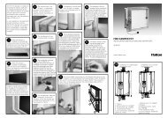
INSTALLATION INSTRUCTIONS<br />
1. Inspect the crating carefully. If there are signs of damage, call the freight carrier before uncrating the units.<br />
Carefully uncrate the units. Check all local codes prior to installation, special requirements may be necessary<br />
depending on local building material construction.<br />
** Important note ** Do not leave unit (s) exposed to extreme temperatures for an extended period<br />
of time, this may cause the protective PVC coating around the unit (s) to become very difficult to<br />
remove.<br />
2. Position the hood near the actual installation site. In case of multiple hoods, check the engineered set of<br />
drawings for locations. Pay close attention to collar sizes <strong>and</strong> fire protection layouts, matching the hood<br />
systems to the correct location shown on the drawings provided.<br />
**Check item numbers on crates / hoods vs. drawing item numbers.<br />
3. Once the hood is carefully removed from the shipping crate <strong>and</strong> set in position, the unit is now ready for<br />
installation. If <strong>Halton</strong> <strong>Company</strong> has supplied a backsplash assembly, then the splash assembly should<br />
be installed first, for installation procedures. (See pg. 4)<br />
4. Hang the hood using ½” threaded rods by attaching the rods to the hood through the hanger brackets that are<br />
welded to the top of the hood. Use of turnbuckles will make final adjustment easier. St<strong>and</strong>ard hanging height<br />
for canopy hoods ranges from 78” min. to 84” max. above the finished floor (per local codes having<br />
jurisdiction). **Noted in installation instructions - (see pg. 6).<br />
**All typical installations for Capture Jet ® series hoods shown on pages 18-22.<br />
5. If Closure Panels are supplied by <strong>Halton</strong> (see pg. 8) for details on the installation.<br />
6. For multiple hoods end to end, or back to back (see pg. 7) for Installation of Splice Strips <strong>and</strong> U-Channels.<br />
7. For hoods equipped with a supply fire damper, it is very important to make sure that the fire damper is set in an<br />
open position before connecting the supply duct.<br />
For units with exhaust fire dampers, (see pg. 9), or supply fire dampers, (see pg. 10) for installation<br />
details.<br />
8. Electrical circuits should be connected according to st<strong>and</strong>ard switch panel wiring diagram, shown on (pg. 11).<br />
For <strong>Halton</strong> Capture Jet ® series hoods, a typical wiring diagram is shown on (pg. 12).<br />
9. Grease filters <strong>and</strong> grease cups must be installed in place before start-up.<br />
10. Install 100 watt maximum light bulbs in st<strong>and</strong>ard inc<strong>and</strong>escent lights or fluorescent bulbs (36” L or 48”L) in<br />
fluorescent lights. **Note: <strong>Halton</strong> does not provide bulbs.<br />
11. Protect the hood from damage under normal job site conditions, until all work is complete <strong>and</strong> system is ready<br />
to be put into operation.<br />
CJOM/2009/rev2/EN