Installation Instruction - H and A Accessories
Installation Instruction - H and A Accessories
Installation Instruction - H and A Accessories

Create successful ePaper yourself
Turn your PDF publications into a flip-book with our unique Google optimized e-Paper software.
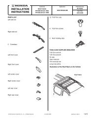
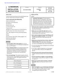
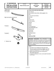
INSTALLATION<br />
INSTRUCTIONS<br />
Accessory Application Publications No.<br />
HEADREST SPEAKER<br />
SYSTEM<br />
S2000<br />
AII 26324<br />
Issue Date<br />
OCT 2004<br />
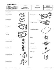
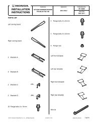
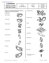
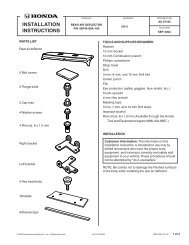
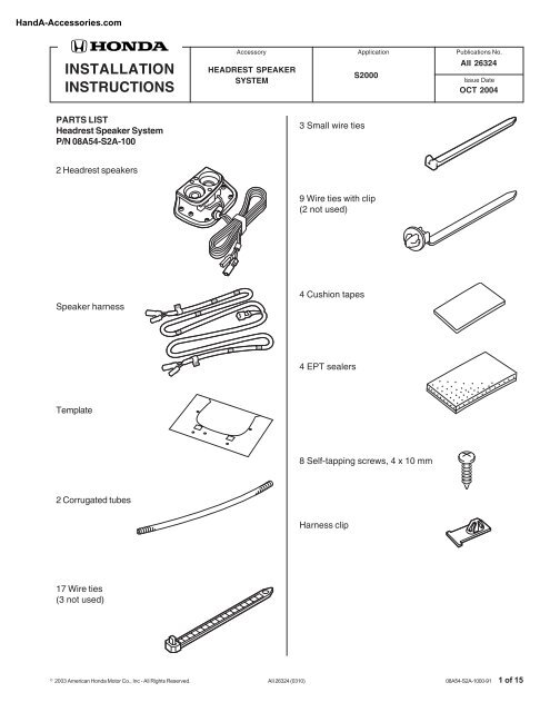
PARTS LIST<br />
Headrest Speaker System<br />
P/N 08A54-S2A-100<br />
3 Small wire ties<br />
2 Headrest speakers<br />
9 Wire ties with clip<br />
(2 not used)<br />
Speaker harness<br />
4 Cushion tapes<br />
4 EPT sealers<br />
Template<br />
8 Self-tapping screws, 4 x 10 mm<br />
2 Corrugated tubes<br />
Harness clip<br />
17 Wire ties<br />
(3 not used)<br />
© 2003 American Honda Motor Co., Inc - All Rights Reserved. AII 26324 (0310) 08A54-S2A-1000-91 1 of 15
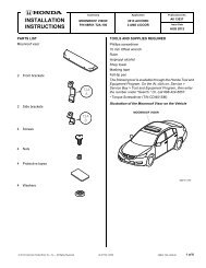
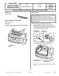
TOOLS AND SUPPLIES REQUIRED<br />
Phillips screwdriver<br />
Flat-tip screwdriver<br />
Diagonal cutters<br />
Ratchet<br />
10 mm, 12 mm, <strong>and</strong> 14 mm Sockets<br />
10 mm Combination wrench<br />
Utility knife<br />
Drill<br />
3 mm, 5 mm, <strong>and</strong> 10 mm Drill bits)<br />
Felt-tip pen<br />
Vinyl tape<br />
Pushpin<br />
Blanket or cardboard<br />
File<br />
Scissors<br />
Piece of steel wire (about 100 cm long)<br />
Isopropyl alcohol<br />
Shop towel<br />
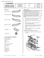
Illustration of the headrest speakers installed on<br />
the car<br />
HEADREST<br />
HEADREST SPEAKER<br />
SPEAKER<br />
3.. Pry up on the three clips <strong>and</strong> remove the<br />
passenger’s side step trim.<br />
CLIPS (3)<br />
PASSENGER'S SIDE<br />
STEP TRIM<br />
4. Remove the passenger's side cowl lining (three<br />
clips).<br />
CLIPS (2)<br />
CLIP<br />
SPEAKER<br />
HARNESS<br />
3429810M<br />
INSTALLATION<br />
Customer Information: The information in this<br />
<strong>Installation</strong> <strong>Instruction</strong> is intended for use only by<br />
skilled technicians who have the proper tools,<br />
equipment, <strong>and</strong> training to correctly <strong>and</strong> safely add<br />
equipment to your vehicle. These procedures should<br />
not be attempted by “do-it-yourselfers.”<br />
NOTE: These instructions show the driver’s side<br />
headrest speaker being installed. The same procedure<br />
applies to installing the passenger’s side headrest<br />
speaker.<br />
1. Make sure you have the anti-theft code for the<br />
radio, then write down the radio station presets.<br />
PASSENGER'S SIDE<br />
COWL LINING<br />
3429580M<br />
2. Disconnect the negative cable from the battery.<br />
2 of 15 AII 26324 (0310) © 2003 American Honda Motor Co., Inc - All Rights Reserved.
5. Pry up on the six clips <strong>and</strong> remove the side<br />
instrument panel lower cover.<br />
7. Remove the two bolts securing the front of the<br />
passenger's seat rails <strong>and</strong> tilt the seat-back<br />
forward. Slide the seat forward, then remove the<br />
two bolts from the rear of the seat rails.<br />
8. Wrap masking tape around the front <strong>and</strong> rear ends<br />
of both seat rails as shown.<br />
SEAT-BACK<br />
SIDE INSTRUMENT<br />
PANEL LOWER<br />
COVER<br />
CLIPS (6)<br />
3429600M<br />
BOLT<br />
BOLT<br />
PASSENGER'S<br />
SEAT<br />
BOLT<br />
6. Remove the passenger's front console side panel<br />
(one self-tapping screw <strong>and</strong> two clips).<br />
SEAT RAIL<br />
SEAT RAIL<br />
PASSENGER'S<br />
FRONT CONSOLE<br />
SIDE PANEL<br />
CLIPS (2)<br />
SEAT RAIL<br />
BOLT<br />
SEAT RAIL<br />
MASKING TAPE<br />
MASKING TAPE<br />
3429591M<br />
9. Remove the passenger's seat from the vehicle.<br />
To prevent damage, put the seat on a blanket or a<br />
large piece of cardboard.<br />
SELF-<br />
TAPPING<br />
SCREW<br />
3429860M<br />
© 2003 American Honda Motor Co., Inc - All Rights Reserved. AII 26324 (0310) 3 of 15
10. Pry up on the three clips <strong>and</strong> remove the driver’s<br />
side step trim.<br />
12. Remove the driver’s front console side panel (one<br />
self-tapping screw <strong>and</strong> two clips).<br />
CLIPS (3)<br />
CLIPS (2)<br />
DRIVER’S SIDE<br />
STEP TRIM<br />
SELF-TAPPING<br />
SCREW<br />
DRIVER'S FRONT<br />
CONSOLE SIDE<br />
PANEL<br />
3429850M<br />
11. Remove the driver's side cowl lining (three clips).<br />
CLIP<br />
CLIP<br />
DRIVER’S SIDE<br />
COWL LINING<br />
3429100M<br />
CLIP<br />
4 of 15 AII 26324 (0310) © 2003 American Honda Motor Co., Inc - All Rights Reserved.
13. Remove the two bolts securing the front of the<br />
driver’s seat rails <strong>and</strong> tilt the seat-back forward.<br />
Slide the seat forward then remove the two bolts<br />
from the rear of the seat rails.<br />
Front bolt tightening torque: 18.6 -24.5 N·m<br />
(1.9-2.5 kgf·m)<br />
Rear bolt tightening torque: 34.3-44.1 N·m<br />
(3.5-4.5 kgf·m)<br />
Reworking on the Headrest Covers<br />
16. Get the template from the kit <strong>and</strong>, using scissors,<br />
cut out the marked area from the template as<br />
shown.<br />
SCISSORS<br />
14. Wrap masking tape around the front <strong>and</strong> rear ends<br />
of both seat rails as shown.<br />
SEAT-BACK<br />
BOLT<br />
BOLT<br />
DRIVER’S<br />
SEAT<br />
BOLT<br />
SEAT<br />
RAIL<br />
TEMPLATE<br />
CUT LINE<br />
3429150M<br />
SEAT RAIL<br />
VEHICLE<br />
HARNESS<br />
CONNECTOR<br />
17. Pry up on the four clips <strong>and</strong> remove the headrest<br />
cover from the driver’s seat.<br />
BOLT<br />
SEAT RAIL SEAT RAIL<br />
DRIVER’S<br />
SEAT<br />
BOLTS (4)<br />
HEADREST NET<br />
MASKING TAPE<br />
MASKING TAPE<br />
3429611M<br />
15. Unplug the vehicle connectors behind the driver’s<br />
seat <strong>and</strong> remove the seat from the vehicle. Be<br />
careful not to damage the vehicle with the seat<br />
rails. To prevent damage, put the seat on a<br />
blanket or a large piece of cardboard.<br />
HEADREST<br />
COVER<br />
CLIPS (4)<br />
3603010M<br />
18. Remove the four bolts fastening the headrest net<br />
to the driver’s seat <strong>and</strong> remove the net.<br />
© 2003 American Honda Motor Co., Inc - All Rights Reserved. AII 26324 (0310) 5 of 15
19. Turn the template upside down, then place it on<br />
the inside of the headrest cover as shown. Align<br />
the two square holes with the clips on the<br />
headrest cover. To mark the passenger's side<br />
headrest cover, use the front of the template.<br />
21. Remove the template from the headrest cover.<br />
Using a pushpin, pierce the headrest cover at<br />
each of the five marks you just made.<br />
DRILL<br />
(3 mm 5 mm Bit)<br />
PUSHPIN<br />
SQUARE<br />
HOLE<br />
CLIP<br />
CLIP<br />
MARK<br />
(5 mm HOLE)<br />
TEMPLATE<br />
(To mark the<br />
passenger's<br />
side headrest<br />
cover, use the<br />
front of the<br />
template.)<br />
20. While holding the template firmly against the<br />
headrest cover, mark the cover at each of the five<br />
round holes in the template with a felt-tip pen.<br />
FELT-TIP PEN<br />
SQUARE<br />
HOLE<br />
HEADREST<br />
COVER<br />
3429630M<br />
HEADREST<br />
COVER<br />
PUSHPIN<br />
DRILL<br />
(3 5 10 mm<br />
BIT)<br />
MARK<br />
(10 mm<br />
HOLE)<br />
MARK<br />
(5 mm HOLE)<br />
3429650M<br />
22. While wearing eye protection, use a drill to drill<br />
one 10 mm hole <strong>and</strong> four 5 mm holes through the<br />
marked locations as shown. First, drill with a<br />
3 mm bit, then a 5 mm bit for the four 5 mm holes.<br />
To drill the 10 mm hole first drill with a 3 mm bit,<br />
<strong>and</strong> then with a 5 mm bit, <strong>and</strong> finish with a 10 mm<br />
bit.<br />
23. Remove any burrs from the edges of the holes<br />
with a file.<br />
24. Repeat steps 17 through 23 on the passenger's<br />
side.<br />
TEMPLATE<br />
3429640M<br />
ROUND<br />
HOLE<br />
6 of 15 AII 26324 (0310) © 2003 American Honda Motor Co., Inc - All Rights Reserved.
Installing the Headrest Speakers<br />
25. Route the 2-pin female <strong>and</strong> male connectors up<br />
through the 10 mm hole you made in step 22. Put<br />
through the 2-pin female connector first.<br />
HEADREST<br />
SPEAKER<br />
HARNESS<br />
GROMMET<br />
HEADREST<br />
SPEAKER HARNESS<br />
2-PIN CONNECTOR<br />
10 mm<br />
HOLE<br />
HEADREST<br />
SPEAKER<br />
HARNESS<br />
HEADREST<br />
COVER<br />
27. Make sure the headrest speaker harness lies flat<br />
<strong>and</strong> straight under the headrest speaker.<br />
HEADREST<br />
COVER<br />
HEADREST<br />
SPEAKER<br />
TOP of<br />
HEADREST<br />
SPEAKER HEADREST<br />
COVER<br />
HEADREST<br />
SPEAKER<br />
HARNESS<br />
2-PIN FEMALE<br />
CONNECTOR<br />
HEADREST<br />
SPEAKER<br />
HEADREST<br />
COVER<br />
HEADREST SPEAKER<br />
HARNESS<br />
(Avoid overlapping the<br />
harness.)<br />
HEADREST<br />
SPEAKER<br />
HARNESS<br />
(Avoid pinching the<br />
harness.)<br />
3429671M<br />
10 mm<br />
HOLE<br />
HEADREST<br />
SPEAKER HARNESS<br />
2-PIN MALE<br />
CONNECTOR<br />
HEADREST<br />
SPEAKER<br />
HARNESS<br />
3429660M<br />
HEADREST<br />
SPEAKER HARNESS<br />
GROMMET<br />
28. Fit the top of the headrest speaker to the headrest<br />
cover first, then push the bottom into position.<br />
Make sure the speaker harness is not pinched.<br />
29. Secure the headrest speaker to the headrest<br />
cover with the four self-tapping screws.<br />
26. Seat the grommet in the 10 mm hole on the<br />
headrest speaker harness as shown.<br />
SELF-TAPPING<br />
SCREW<br />
HEADREST<br />
SPEAKER<br />
HEADREST<br />
COVER<br />
3429680M<br />
© 2003 American Honda Motor Co., Inc - All Rights Reserved. AII 26324 (0310) 7 of 15
30. Using scissors, cut the EPT sealer in half.<br />
31. Using isopropyl alcohol on a shop towel,<br />
thoroughly clean the areas where the EPT sealers<br />
will attach.<br />
32. Wrap one piece of the EPT sealer around the<br />
speaker harness as shown.<br />
33. Route the headrest speaker harness to the left of<br />
the headrest cover <strong>and</strong> secure it to the headrest<br />
cover with the remaining piece of EPT sealer.<br />
Routing the Headrest Speaker Harnesses<br />
35. Remove the Velcro tape from the headrest trim<br />
cover.<br />
BENT END<br />
of WIRE<br />
PIECE OF WIRE<br />
SEAT BELT<br />
BUCKLE<br />
PIECE<br />
OF WIRE<br />
EPT<br />
SEALER<br />
EPT SEALER<br />
(Cut in half.)<br />
HEADREST<br />
COVER<br />
VINYL TAPE<br />
BLANKET or<br />
CARDBOARD<br />
EPT SEALER<br />
(Wrap around the<br />
headrest speaker<br />
harness.)<br />
HEADREST<br />
SPEAKER<br />
HARNESS<br />
3429691M<br />
34. Repeat steps 25 through 33 for the passenger's<br />
side.<br />
VELCRO<br />
TAPE<br />
HEADREST<br />
TRIM COVER<br />
OPENING<br />
DRIVER’S SEAT<br />
SEAT-BACK<br />
TRIM COVER<br />
OPENING<br />
3429701M<br />
36. Place the driver’s seat on its side so that the seat<br />
belt buckle is facing up.<br />
37. Bend back one end of a piece of wire, then wrap<br />
vinyl tape around the end as shown.<br />
38. Thread the bent end of the wire through the<br />
opening in the seat-back trim cover under the<br />
driver’s seat, then through the opening in the<br />
headrest trim cover, as shown. Make sure not to<br />
damage the driver’s seat.<br />
8 of 15 AII 26324 (0310) © 2003 American Honda Motor Co., Inc - All Rights Reserved.
39. Remove the vinyl tape from the bent end of the<br />
wire, then secure the headrest speaker 2-pin<br />
connector harness to the wire <strong>and</strong> headrest<br />
speaker harness, as shown.<br />
HEADREST SPEAKER<br />
HARNESS 2-PIN CONNECTOR<br />
42. Wrap the corrugated tube around the headrest<br />
speaker harness as shown.<br />
HEADREST<br />
SPEAKER HARNESS<br />
CORRUGATED TUBE<br />
HEADREST<br />
SPEAKER HARNESS<br />
2-PIN CONNECTOR<br />
10 mm<br />
WIRE<br />
HEADREST<br />
SPEAKER<br />
HARNESS<br />
80 mm<br />
WIRE<br />
VINYL<br />
TAPE<br />
HEADREST<br />
SPEAKER<br />
HARNESS<br />
VINYL<br />
TAPE<br />
VINYL TAPE<br />
SEAT-BACK<br />
TRIM COVER<br />
HEADREST<br />
SPEAKER<br />
HARNESS<br />
DRIVER’S<br />
SEAT<br />
SEAT-BACK<br />
TRIM COVER<br />
SEAMS<br />
CORRUGATED<br />
TUBE<br />
3429721M<br />
HEADREST SPEAKER<br />
HARNESS 2-PIN CONNECTOR<br />
3619010M<br />
40. Thread the wire <strong>and</strong> the 2-pin connector back<br />
down to the underside of the driver’s seat along<br />
the seams of the seat-back trim cover as shown.<br />
41. Remove the headrest speaker harness 2-pin<br />
connector from the wire.<br />
43. Continue wrapping the corrugated tube up to a<br />
point about 10 mm away from the end of the 2-pin<br />
connector. Secure the end of the corrugated tube<br />
to the headrest speaker harness with vinyl tape.<br />
44. Feed 80 mm of the corrugated tube under the<br />
seat-back trim cover as shown.<br />
45. Press <strong>and</strong> push the headrest speaker harness into<br />
to the seams of the seat-back trim cover with your<br />
fingers, until it is as unnoticeable as possible.<br />
SEAT-BACK<br />
TRIM COVER<br />
SEAMS<br />
(Push <strong>and</strong><br />
press with your<br />
fingers.)<br />
HEADREST<br />
SPEAKER<br />
HARNESS<br />
DRIVER’S SEAT<br />
SEAT-BACK<br />
3429711M<br />
© 2003 American Honda Motor Co., Inc - All Rights Reserved. AII 26324 (0310) 9 of 15
46. Reinstall the Velcro tapes on the headrest trim<br />
cover, then attach the headrest net to the driver’s<br />
seat with four bolts.<br />
VELCRO<br />
TAPE<br />
DRIVER’S<br />
SEAT<br />
48. Repeat steps 35 through 47 for the passenger's<br />
side.<br />
Securing the Headrest Speaker Harness to the<br />
Seat Panel<br />
Driver's Seat<br />
49. To secure the headrest speaker harness to the<br />
seat panel, route the headrest speaker harness<br />
around the back of the seat, then attach the wire<br />
tie with clip to the harness at a point 140 mm<br />
away from the end of the 2-pin connector. Push<br />
the clip of the wire tie with clip you just attached<br />
into the hole in the seat panel.<br />
BOLT<br />
HEADREST NET<br />
3603050M<br />
47. Loop the excess headrest speaker harness, <strong>and</strong><br />
reinstall the headrest cover. Do not pinch the<br />
headrest speaker harness between the headrest<br />
cover <strong>and</strong> driver’s seat-back.<br />
WIRE TIE<br />
WITH CLIP<br />
VEHICLE<br />
HARNESS<br />
HEADREST<br />
SPEAKER<br />
HARNESS<br />
HEADREST<br />
SPEAKER<br />
HARNESS<br />
2-PIN<br />
CONNECTOR<br />
140 mm<br />
HEADREST SPEAKER<br />
HARNESS<br />
(To prevent pinching,<br />
make a loop in the<br />
harness.)<br />
SEAT<br />
PANEL<br />
CUSHION<br />
TAPE<br />
SMALL<br />
WIRE TIE<br />
WIRE TIE<br />
WITH CLIP<br />
HEADREST<br />
SPEAKER<br />
HARNESS<br />
DRIVER’S<br />
SEAT-BACK<br />
HEADREST<br />
COVER<br />
3619020M<br />
3429822M<br />
50. Secure the headrest speaker harness to the<br />
vehicle harness with two small wire ties in the<br />
areas shown.<br />
51. Using isopropyl alcohol on a shop towel,<br />
thoroughly clean the area where the cushion tape<br />
will attach, then secure the headrest speaker<br />
harness to the seat panel with the cushion tape.<br />
10 of 15 AII 26324 (0310) © 2003 American Honda Motor Co., Inc - All Rights Reserved.
Passenger's Seat<br />
52. Route the headrest speaker harness as shown,<br />
then attach the wire tie with clip to the harness at<br />
a point 140 mm away from the 2-pin connector.<br />
Push the clip of the wire tie with clip you just<br />
attached into the hole in the seat panel.<br />
53. Using a isopropyl alcohol on a shop towel,<br />
thoroughly clean the area where the cushion tape<br />
will be attached.<br />
HEADREST<br />
SPEAKER HARNESS<br />
2-PIN CONNECTOR<br />
HEADREST<br />
SPEAKER HARNESS<br />
WIRE TIE<br />
WITH CLIP<br />
SEAT PANEL<br />
56. Above the opening in the driver’s side front<br />
console side panel, locate the 4-pin connector<br />
taped to the vehicle harness <strong>and</strong> remove the vinyl<br />
tape to free the 4-pin connector.<br />
SPEAKER<br />
HARNESS<br />
4-PIN<br />
CONNECTOR<br />
VEHICLE HARNESS<br />
4-PIN CONNECTOR<br />
VINYL<br />
TAPE<br />
VEHICLE<br />
HARNESS<br />
SPEAKER<br />
HARNESS<br />
FRONT CONSOLE<br />
SIDE PANEL OPENING<br />
140 mm<br />
CONNECTION<br />
WIRE TIE<br />
VEHICLE<br />
HARNESS<br />
3429740M<br />
WIRE TIE<br />
WITH CLIP<br />
WIRE TIE<br />
WITH CLIP<br />
CUSHION<br />
TAPE<br />
3429832M<br />
HEADREST<br />
SPEAKER HARNESS<br />
54. Secure the headrest speaker harness to the seat<br />
panel with the two wire ties with clip <strong>and</strong> cushion<br />
tape in the areas shown.<br />
57. Plug the speaker harness 4-pin connector into the<br />
vehicle harness 4-pin connector you just unplugged.<br />
58. Secure the 4-pin connectors with a wire tie as shown<br />
to the same place it was secured with the vinyl tape.<br />
59. From the center console, route the label end (marked<br />
DR) of the speaker harness above the steering column<br />
shaft to the left along the vehicle harness.<br />
Routing the Speaker Harnesses<br />
55. Route the label end (marked AS) of the speaker<br />
harness to the passenger's seat through the<br />
opening in the front console side panel as shown.<br />
STEERING<br />
COLUMN<br />
SHAFT<br />
VEHICLE<br />
HARNESS<br />
WIRE TIE<br />
SPEAKER<br />
HARNESS<br />
SPEAKER<br />
HARNESS<br />
LABEL<br />
(marked AS)<br />
WIRE<br />
TIE<br />
VEHICLE<br />
HARNESS<br />
CENTER<br />
CONSOLE<br />
3429750M<br />
OPENING in FRONT<br />
CONSOLE SIDE PANEL<br />
© 2003 American Honda Motor Co., Inc - All Rights Reserved. AII 26324 (0310) 11 of 15
60. Secure the speaker harness to the vehicle harness<br />
with the three wire ties in the areas shown.<br />
65. Route the speaker harness routed to the<br />
assistant’s side in step 49 to the right along the<br />
vehicle pipe; then, secure the harness to the<br />
vehicle frame <strong>and</strong> pipe with the two wire ties.<br />
VEHICLE<br />
HARNESS<br />
WIRE<br />
TIE<br />
SPEAKER<br />
HARNESS<br />
FUSE<br />
CASE<br />
66. Align the green tape on the speaker harness with<br />
the vehicle hook <strong>and</strong> secure it to the vehicle hook<br />
<strong>and</strong> vehicle harness with the two wire ties. If the<br />
car you are working on is equipped with the<br />
security system, secure the speaker harness to<br />
the security system harness on the side of the<br />
vehicle hook.<br />
WIRE TIE<br />
VEHICLE<br />
PIPE<br />
3429760M<br />
61. Route the speaker harness above the fuse case to<br />
the rear along the vehicle harness.<br />
62. Secure the speaker harness to the vehicle<br />
harness with the three wire ties in the areas<br />
shown.<br />
63. On the driver’s side, turn over the floor carpet,<br />
then route the speaker harness to the rear along<br />
the vehicle harness <strong>and</strong> out through the slit in the<br />
floor carpet as shown.<br />
SPEAKER<br />
HARNESS<br />
VEHICLE<br />
FRAME<br />
3429780M<br />
64. Align the green tape on the speaker harness with<br />
the slit in the floor carpet, <strong>and</strong> secure the harness<br />
to the vehicle harness with the three wire ties as<br />
shown.<br />
FLOOR<br />
CARPET<br />
SLIT in<br />
FLOOR<br />
CARPET<br />
VEHICLE<br />
HARNESS<br />
SPEAKER<br />
HARNESS<br />
GREEN<br />
TAPE<br />
WIRE TIE<br />
WIRE TIE<br />
SPEAKER<br />
HARNESS<br />
VEHICLE<br />
HARNESS<br />
SLIT in<br />
FLOOR<br />
CARPET<br />
3429770M<br />
12 of 15 AII 26324 (0310) © 2003 American Honda Motor Co., Inc - All Rights Reserved.
67. Align the harness clip with the green tape on the<br />
speaker harness <strong>and</strong> secure with the vinyl tape.<br />
VEHICLE<br />
HOOK<br />
SECURITY<br />
SYSTEM<br />
HARNESS<br />
SPEAKER<br />
HARNESS<br />
VEHICLE<br />
HOOK<br />
GREEN<br />
TAPE<br />
SPEAKER<br />
HARNESS<br />
GREEN<br />
TAPE<br />
VINYL<br />
TAPE<br />
WIRE<br />
TIE<br />
Security System Equipped<br />
WIRE TIE<br />
GREEN<br />
TAPE<br />
HARNESS<br />
CLIP<br />
VEHICLE<br />
HARNESS<br />
WIRE<br />
TIE<br />
SPEAKER<br />
HARNESS<br />
VEHICLE<br />
PANEL<br />
HARNESS<br />
CLIP<br />
3429790M<br />
68. Push the harness clip attached to the speaker<br />
harness into the hole in the vehicle panel.<br />
70. Attach the wire tie with clip to the speaker harness<br />
where the green tape is wrapped, then push the<br />
clip into the hole in the vehicle panel.<br />
SLIT in<br />
FLOOR<br />
CARPET<br />
GREEN<br />
TAPE<br />
GREEN<br />
TAPE<br />
WIRE TIE<br />
WITH CLIP<br />
SPEAKER<br />
HARNESS<br />
FLOOR<br />
CARPET<br />
CUSHION<br />
TAPE<br />
SIDE<br />
STEP<br />
VEHICLE<br />
PANEL<br />
3429801M<br />
71. Using isopropyl alcohol on a shop towel,<br />
thoroughly clean the areas where the cushion<br />
tapes will attach. Secure the speaker harness to<br />
the vehicle panel with two cushion<br />
tapes.<br />
69. On the passenger's side, turn over the floor carpet<br />
<strong>and</strong> route the speaker harness to the rear along<br />
the side step, then pull the harness out through<br />
the slit in the floor carpet <strong>and</strong> align its green tape<br />
with the slit in the floor carpet.<br />
© 2003 American Honda Motor Co., Inc - All Rights Reserved. AII 26324 (0310) 13 of 15
Installing the Driver's Seat in the Vehicle<br />
72. Secure the speaker harness to the seat panel.<br />
73. Place the driver’s seat in the vehicle.<br />
74. Cut the EPT sealer down the middle. Wrap the<br />
pieces around the female 2-pin connectors of the<br />
headrest speaker <strong>and</strong> speaker harnesses.<br />
EPT SEALER<br />
(Cut into<br />
halves.)<br />
HEADREST<br />
SPEAKER<br />
SPEAKER HARNESS HARNESS<br />
2-PIN CONNECTOR 2-PIN<br />
CONNECTOR<br />
EPT SEALER<br />
77. If the security system is installed on the drivers<br />
seat side: connect the speaker harness 2-pin<br />
connectors to the headrest speaker harness 2-pin<br />
connectors, then secure them to the relay of the<br />
security system with the small wire tie, as shown.<br />
EPT SEALER<br />
(Cut into halves.)<br />
HEADREST<br />
SPEAKER HARNESS<br />
2-PIN CONNECTOR<br />
EPT<br />
SEALER<br />
SPEAKER<br />
HARNESS<br />
2-PIN<br />
CONNECTOR<br />
CONNECTOR<br />
WIRE TIE<br />
WITH CLIP<br />
SECURITY<br />
SYSTEM<br />
RELAY<br />
SECURITY<br />
UNIT<br />
CONNECTOR<br />
GREEN<br />
TAPE<br />
SPEAKER<br />
HARNESS<br />
SMALL<br />
WIRE TIE<br />
GREEN<br />
TAPE<br />
SMALL<br />
WIRE TIE<br />
HEADREST<br />
SPEAKER<br />
HARNESS<br />
SEAT<br />
PANEL<br />
3707050M<br />
SMALL<br />
WIRE TIE<br />
SPEAKER<br />
HARNESS<br />
WIRE TIE<br />
WITH CLIP<br />
SECURITY<br />
HARNESS<br />
HEADREST<br />
SPEAKER<br />
HARNESS<br />
SMALL<br />
WIRE TIE<br />
3619040M<br />
75. If the security system is not installed on the<br />
driver's seat side; connect the speaker harness<br />
2-pin connectors to the headrest speaker harness<br />
2-pin connectors, then attach the wire tie with clip<br />
to the connectors <strong>and</strong> push the clip of the wire tie<br />
with clip into the hole in the seat panel.<br />
78. Align the green tape on the speaker harness with<br />
the wire tie with clip fastening the security<br />
harness, <strong>and</strong> secure the speaker harness to the<br />
security harness with the small wire tie.<br />
76. Align the green tape on the speaker harness with<br />
the small wire tie secured to the center of the seat<br />
panel in step 49, then secure the harness to the<br />
headrest speaker harness with the small wire tie.<br />
14 of 15 AII 26324 (0310) © 2003 American Honda Motor Co., Inc - All Rights Reserved.
Installing the Passenger's Seat in the Vehicle<br />
79. Place the passenger's seat in the vehicle.<br />
80. Cut the EPT sealer down the middle. Wrap the<br />
pieces around the 2-pin female connectors of the<br />
headrest speaker harness <strong>and</strong> speaker harness.<br />
EPT SEALER<br />
(Cut into halves.)<br />
HEADREST<br />
SPEAKER<br />
HARNESS 2-PIN<br />
CONNECTOR<br />
EPT<br />
SEALER<br />
SPEAKER<br />
HARNESS<br />
2-PIN<br />
CONNECTOR<br />
84. Check that all wire harnesses are routed properly<br />
<strong>and</strong> all connectors are plugged in.<br />
85. Reconnect the negative cable to the battery.<br />
86. Enter the customer’s radio anti-theft code, <strong>and</strong><br />
reset the radio station presets.<br />
87. Reset the clock.<br />
88. Check operation of the Headrest Speaker<br />
according to the Owner’s Manual provided.<br />
CONNECTOR<br />
WIRE TIE<br />
WITH CLIP<br />
SPEAKER<br />
HARNESS<br />
SEAT<br />
PANEL<br />
HEADREST<br />
SPEAKER<br />
HARNESS<br />
SMALL<br />
WIRE TIE<br />
WIRE TIE<br />
WITH CLIP<br />
(Step 48.)<br />
3619030M<br />
GREEN<br />
TAPE<br />
81. Connect the speaker harness 2-pin connectors to<br />
the headrest speaker harness 2-pin connectors,<br />
then secure them to the seat panel by pushing the<br />
clip of the wire tie with clip into the hole in the seat<br />
panel.<br />
82. Align the green tape on the speaker harness with<br />
the wire tie with clip installed at the center of the<br />
seat panel in step 52, then secure the harness to<br />
the headrest speaker harness with the small wire<br />
tie, as described.<br />
83. Reinstall all removed parts. Torque the seat front<br />
mounting bolts to 22 N. m (16lb-ft). Torque the<br />
seat rear mounting bolts to 29 N. m (22lb-ft).<br />
© 2003 American Honda Motor Co., Inc - All Rights Reserved. AII 26324 (0310) 15 of 15