installation instructions - H and A Accessories
installation instructions - H and A Accessories
installation instructions - H and A Accessories

Create successful ePaper yourself
Turn your PDF publications into a flip-book with our unique Google optimized e-Paper software.
INSTALLATION<br />
INSTRUCTIONS<br />
Accessory Application Publications No.<br />
All 24107<br />
AIR CONDITIONER<br />
ELEMENT<br />
(DX)<br />
Issue Date<br />
DEC 2002<br />
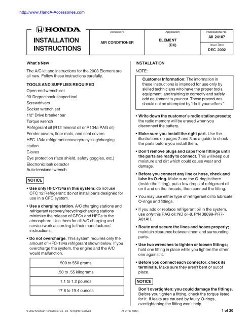
What’s New<br />
INSTALLATION<br />
The A/C kit <strong>and</strong> <strong>instructions</strong> for the 2003 Element are<br />
all new. Follow these <strong>instructions</strong> carefully.<br />
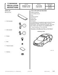
TOOLS AND SUPPLIES REQUIRED<br />
Open-end wrench set<br />
90-Degree hook-shaped tool<br />
Screwdrivers<br />
Socket wrench set<br />
1/2" Drive breaker bar<br />
Torque wrench<br />
Refrigerant oil (R12 mineral oil or R134a PAG oil)<br />
Fender covers, floor mats, <strong>and</strong> seat covers<br />
HFC-134a refrigerant recovery/recycling/charging<br />
station<br />
Gloves<br />
Eye protection (face shield, safety goggles, etc.)<br />
Electronic leak detector<br />
Auto-tensioner wrench<br />
NOTICE<br />
• Use only HFC-134a in this system; do not use<br />
CFC 12 Refrigerant; do not install parts designed for<br />
use in a CFC system.<br />
• Use a charging station. A/C charging stations <strong>and</strong><br />
refrigerant recovery/recycling/charging stations<br />
minimize the release of CFCs <strong>and</strong> HFCs to the<br />
atmosphere. Use them for all A/C charging <strong>and</strong><br />
service work according to their manufactures’<br />
<strong>instructions</strong>.<br />
• Do not overcharge. This system requires only the<br />
amount of HFC-134a refrigerant shown below. If you<br />
overcharge the system, the engine <strong>and</strong> the A/C<br />
would malfunction.<br />
500 to 550 grams<br />
.50 to .55 kilograms<br />
1.1 to 1.2 pounds<br />
NOTE:<br />
Customer Information: The information in<br />
these <strong>instructions</strong> is intended for use only by<br />
skilled technicians who have the proper tools,<br />
equipment, <strong>and</strong> training to correctly <strong>and</strong> safely<br />
add equipment to your car. These procedures<br />
should not be attempted by “do-it-yourselfers.”<br />
• Write down the customer’s radio station presets;<br />
the radio memory will be erased when you<br />
disconnect the battery.<br />
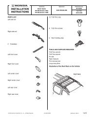
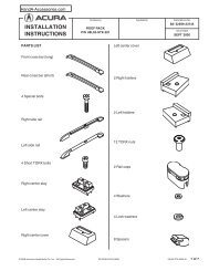
• Make sure you install the right part. Use the<br />
illustrations on pages 2 <strong>and</strong> 3 as a guide to check<br />
the parts before you install them.<br />
• Don’t remove plugs <strong>and</strong> caps from fittings until<br />
the parts are ready to connect. This will keep out<br />
moisture <strong>and</strong> dirt which could cause wear <strong>and</strong><br />
damage.<br />
• Before you connect any line or hose, check <strong>and</strong><br />
lube its O-ring. Make sure the O-ring is there<br />
(inside the fitting), put a few drops of refrigerant oil<br />
on it <strong>and</strong> on the threads, then connect the fitting.<br />
• You may use either type of refrigerant oil to lubricate<br />
O-rings <strong>and</strong> fittings.<br />
• If you add or replace refrigerant oil in the system,<br />
use only this PAG oil: ND oil-8, P/N 38899-PR7-<br />
A01AH.<br />
• Route <strong>and</strong> secure the lines <strong>and</strong> hoses properly;<br />
maintain clearance between them <strong>and</strong> surrounding<br />
parts.<br />
• Use two wrenches to tighten or loosen fittings;<br />
hold one fitting in place while you tighten the other<br />
one against it.<br />
• Before you connect each connector, check its<br />
terminals. Make sure they aren’t bent or out of<br />
place.<br />
NOTICE<br />
17.6 to 19.4 ounces<br />
Don’t overtighten; you could damage the fittings.<br />
Before you tighten a fitting, check the torque listed<br />
for it. If leaks are caused by faulty O-rings,<br />
overtightening the fitting won’t help.<br />
© 2002 American Honda Motor Co., Inc - All Rights Reserved. AII 24107 (0212) 1 of 20
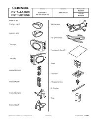
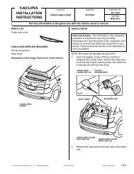
Parts index<br />
39794-S0K-A01<br />
8005X-SCV-A50<br />
38920-PZD-A01<br />
2 of 20 AII 24107 (0212) © 2002 American Honda Motor Co., Inc - All Rights Reserved.
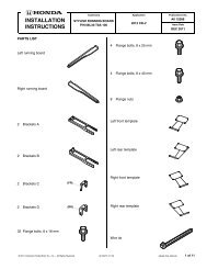
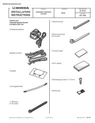
80342-SCV-A02<br />
80315-SCV-A11<br />
93403-06016-05<br />
© 2002 American Honda Motor Co., Inc - All Rights Reserved. AII 24107 (0212) 3 of 20
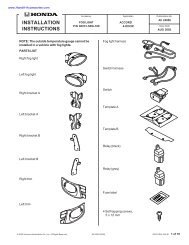
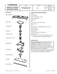
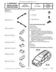
PARTS LIST<br />
KIT No.80000-SCV-A50<br />
COMPRESSOR 38800-PZD-A01 1<br />
COMPRESSOR BRACKET 38930-PNA-000 1<br />
COMPRESSOR BELT 38920-PZD-A01<br />
38920-PZD-A00 1<br />
CONDENSER FAN 38605-PZD-A01 1<br />
CONDENSER 80100-SCV-A01 1<br />
LEFT UPPER CONDENSER BRACKET 80111-S9A-000 1<br />
RIGHT UPPER CONDENSER BRACKET 80112-S9A-000 1<br />
SUCTION HOSE 80311-SCV-A01 1<br />
SUCTION PIPE HOSE CLAMPA 80361-SK7-010 1<br />
SUCTION PIPE CLAMP 80364-SF1-000 2<br />
DISCHARGE HOSE 80315-SCV-A11<br />
80315-SCV-A01 1<br />
A/C PIPE UNIT 80320-SCV-A01 1<br />
RECEIVER PIPE A 80341-SCV-A01 1<br />
RECEIVER PIPE B 80342-SCV-A02<br />
80342-SCV-A01 1<br />
RECEIVER PIPE CLIP B 80384-SM4-A01 2<br />
CLIP 8mm 91548-SR3-003 2<br />
EVAPORATOR 80210-S5D-G03 1<br />
EVAPORATOR SENSOR 80560-S5A-941 1<br />
DRAIN HOSE 80271-S9A-000 1<br />
DRAIN HOSE CLIP 91597-S5H-T31 1<br />
POWER RELAY 39794-S0K-A10 39794-S0K-A01<br />
2<br />
A/C INFORMATION LABEL 80050-SR3-H00 1<br />
A/C KIT LABEL 8005X-SCV-A50<br />
800XX-XXX-XXX 1<br />
A/C KNOB 79601-SCV-A01 1<br />
TURN DIAL COMP 79604-SCV-A01 1<br />
A/C MODE DISPLAY 79606-SCV-A01 1<br />
WASHER BOLT 6x16mm (GRAY) 93403-06016-05 2<br />
WASHER BOLT 6x12mm (YELLOW) 93403-06012-08 3<br />
WASHER BOLT 6x16mm (YELLOW) 93403-06016-08 2<br />
FLANGE BOLT 6x25mm (YELLOW) 95701-06025-08 2<br />
FLANGE BOLT 6x30mm (YELLOW) 95701-06030-08 1<br />
FLANGE BOLT 10x40mm (YELLOW) 95701-10040-08 2<br />
FLANGE BOLT 8x65mm (YELLOW) 90024-PNA-000 2<br />
FLANGE BOLT 8x80mm (YELLOW) 90023-PNA-000 2<br />
FLANGE NUT 6mm (YELLOW) 94050-06080 2<br />
PAINT CUTTING NUT 6mm (YELLOW) 90361-SV4-003 2<br />
4 of 20 AII 24107 (0212) © 2002 American Honda Motor Co., Inc - All Rights Reserved.
1. Remove the negative battery cable.<br />
NOTE: Do not allow the negative cable to make contact with the positive cable.<br />
Disconnect the negative<br />
terminal from the battery.<br />
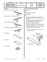
2. Remove the passenger’s dashboard under cover <strong>and</strong> glove box.<br />
Remove the two washer bolts<br />
<strong>and</strong> remove the the glove box.<br />
Re<strong>installation</strong> torque: 5 N·m (3.6 lb-ft)<br />
Remove the passenger’s kick panel. (2 clips)<br />
Remove the passenger’s<br />
dashboard under cover.<br />
(3 clips)<br />
Forward<br />
© 2002 American Honda Motor Co., Inc - All Rights Reserved. AII 24107 (0212) 5 of 20
3. Cut out the dashboard frame <strong>and</strong> remove the glove box frame.<br />
Remove the two relay sockets <strong>and</strong> the harness clip.<br />
Attach protective tape (duct tape) to the<br />
dashboard frame <strong>and</strong> blower unit.<br />
Do not damage the cabin harness<br />
or blower unit.<br />
Re<strong>installation</strong> torque: 5 N·m (3.6 lb-ft)<br />
Remove <strong>and</strong> discard frame.<br />
Remove the glove box frame.<br />
Cut out the dashboard frame as shown.<br />
4. Remove the ECM/PCM <strong>and</strong> disconnect the connectors.<br />
Remove the ECM/PCM<br />
<strong>and</strong> the ECM/PCM bracket.<br />
(three washer bolts)<br />
(two flange nuts)<br />
Re<strong>installation</strong> torque: 9.8 N·m (7.2 lb-ft)<br />
Disconnect the three<br />
ECM/PCM connectors<br />
<strong>and</strong> the 20-pin<br />
harness connector.<br />
Pry to<br />
remove.<br />
Disconnect.<br />
Recirculation<br />
control motor<br />
connector<br />
Disconnect.<br />
Power<br />
transistor<br />
connector<br />
Blower<br />
motor<br />
connector<br />
Pry to<br />
remove.<br />
Disconnect.<br />
Pry to<br />
remove.<br />
6 of 20 AII 24107 (0212) © 2002 American Honda Motor Co., Inc - All Rights Reserved.
5. Remove the blower unit.<br />
Remove bolts.<br />
Remove blower unit<br />
while pulling down<br />
on frame.<br />
Remove nut.<br />
6. Install the evaporator.<br />
Remove bolt.<br />
Remove nut.<br />
Re<strong>installation</strong> torque: 9.8 N·m (7.2 lb-ft)<br />
Remove the heater<br />
plate <strong>and</strong> discard.<br />
Push the A/C hole plug toward<br />
the engine compartment.<br />
Remove <strong>and</strong> discard plug.<br />
Remove the<br />
expansion<br />
valve cover.<br />
(six screws)<br />
Install the<br />
expansion<br />
valve cover.<br />
(six screws)<br />
Install the evaporator into<br />
the heater unit.<br />
© 2002 American Honda Motor Co., Inc - All Rights Reserved. AII 24107 (0212) 7 of 20
7. Install the evaporator sensor.<br />
Remove the<br />
driver’s dashboard<br />
lower cover.<br />
Plug in connector.<br />
Heater<br />
case<br />
Install evaporator<br />
sensor <strong>and</strong> turn<br />
clockwise until it clicks.<br />
Heater<br />
case<br />
Blue<br />
tape<br />
Remove <strong>and</strong><br />
discard cover.<br />
8. Reinstall the blower unit.<br />
Attach connector.<br />
Untape sensor connector<br />
from the harness.<br />
Reinstall bolts.<br />
Re<strong>installation</strong> torque:<br />
9.8 N·m (7.2 lb-ft)<br />
Reinstall<br />
blower<br />
unit.<br />
Reinstall nut.<br />
Re<strong>installation</strong> torque:<br />
9.8 N·m (7.2 lb-ft)<br />
Reinstall bolt.<br />
Re<strong>installation</strong> torque: 9.8 N·m (7.2 lb-ft)<br />
Reinstall nut.<br />
Re<strong>installation</strong> torque:<br />
9.8 N·m (7.2 lb-ft)<br />
8 of 20 AII 24107 (0212) © 2002 American Honda Motor Co., Inc - All Rights Reserved.
9. Reinstall the ECM/PCM unit <strong>and</strong> the connectors.<br />
Reinstall the ECM/PCM bracket <strong>and</strong> the ECM/PCM.<br />
(three washer bolts <strong>and</strong> two flange nuts)<br />
Re<strong>installation</strong> torque: 9.8 N·m (7.2 lb-ft)<br />
Connect the three ECM/PCM<br />
connectors <strong>and</strong> the 20-pin<br />
harness connector.<br />
Reattach.<br />
Reconnect.<br />
Recirculation<br />
control<br />
motor<br />
connector<br />
Reconnect.<br />
Power<br />
transistor<br />
connector<br />
Reattach.<br />
10. Install the A/C switch knob <strong>and</strong> the A/C mode display.<br />
Reattach.<br />
Blower<br />
motor<br />
connector<br />
Reconnect.<br />
Reattach.<br />
Reinstall the temperature<br />
control dial.<br />
Reinstall the mode control dial.<br />
Turn the<br />
temperature<br />
control dial<br />
to MAX COOL,<br />
<strong>and</strong> remove<br />
temperature<br />
control dial.<br />
Install the new<br />
A/C switch knob.<br />
Turn the mode<br />
control dial to<br />
VENT, <strong>and</strong><br />
remove the dial.<br />
Remove the A/C switch<br />
lid, <strong>and</strong> discard the lid.<br />
Install the new mode<br />
control display.<br />
Apply protective tape<br />
as shown.<br />
(masking tape)<br />
Remove the mode control<br />
display, <strong>and</strong> discard.<br />
© 2002 American Honda Motor Co., Inc - All Rights Reserved. AII 24107 (0212) 9 of 20
11. Install the drain hose.<br />
Heat<br />
shield<br />
Remove the four<br />
flange bolts, <strong>and</strong><br />
remove the heat shield.<br />
Reinstall the heat shield<br />
with four flange bolts.<br />
Re<strong>installation</strong> torque:<br />
9.8 N·m (7.2 lb-ft)<br />
Install drain hose<br />
<strong>and</strong> position white<br />
paint mark facing up.<br />
Paint mark<br />
Install<br />
clip.<br />
Remove <strong>and</strong> discard drain nozzle cap.<br />
12. Reinstall the removed cabin parts.<br />
o<br />
Check if completed.<br />
Removed parts<br />
o<br />
o<br />
o<br />
o<br />
o<br />
o<br />
o<br />
Passenger’s dashboard under cover<br />
Glove box<br />
Passenger’s kick panel<br />
Right side kick panel<br />
Glove box frame<br />
Relay sockets <strong>and</strong> harness clip<br />
Driver’s dashboard lower cover.<br />
10 of 20 AII 24107 (0212) © 2002 American Honda Motor Co., Inc - All Rights Reserved.
13. Remove the front bumper.<br />
Remove blulkhead cover.<br />
(five clips)<br />
Remove the<br />
splashshield.<br />
(ten clips)<br />
Front<br />
bumper<br />
Remove the front bumper.<br />
(thirteen clips, four washer bolts, <strong>and</strong> two screws)<br />
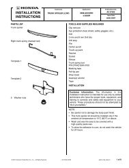
14. Remove the bulkhead <strong>and</strong> upper radiator bracket.<br />
Disconnect reservoir hose,<br />
<strong>and</strong> remove the reservoir.<br />
Remove<br />
reservoir<br />
bolt.<br />
Remove the upper<br />
radiator bracket.<br />
Remove washer bolts.<br />
Re<strong>installation</strong> torque:<br />
9.8 N·m (7.2 lb-ft)<br />
Remove<br />
washer<br />
bolts.<br />
Remove the upper<br />
radiator bracket.<br />
Remove washer bolts.<br />
Re<strong>installation</strong> torque:<br />
9.8 N·m (7.2 lb-ft)<br />
Remove bulkhead.<br />
Remove washer bolts.<br />
Re<strong>installation</strong> torque: 9.8 N·m (7.2 lb-ft)<br />
© 2002 American Honda Motor Co., Inc - All Rights Reserved. AII 24107 (0212) 11 of 20
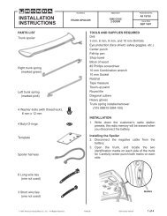
15. Remove the alternator belt.<br />
Apply pressure to the tool in this direction to loosen belt.<br />
Install<br />
tool<br />
Remove <strong>and</strong> discard belt.<br />
16. Remove the power steering pump <strong>and</strong> altermator.<br />
Lift the power steering reservoir from its mount <strong>and</strong> position a side.<br />
Lift the power steering pump from its mount <strong>and</strong> position a side.<br />
DO NOT disconnect the power steering hoses.<br />
Re<strong>installation</strong> torque:<br />
8 N·m (6 lb-ft)<br />
Remove the nut <strong>and</strong> terminal.<br />
Disconnect.<br />
Pry harness clip.<br />
Remove two bolts.<br />
(M8x45mm)<br />
Re<strong>installation</strong> torque:<br />
24 N·m (18 lb-ft)<br />
Remove the alternator.<br />
Remove three bolts.<br />
(2-M8x45mm)<br />
(1-M8x105mm)<br />
Re<strong>installation</strong> torque: 24 N·m (18 lb-ft)<br />
12 of 20 AII 24107 (0212) © 2002 American Honda Motor Co., Inc - All Rights Reserved.
17. Install the compressor bracket <strong>and</strong> compressor.<br />
Install the two new flange bolts.<br />
Installation torque: 44 N·m (32 lb-ft)<br />
Position the two compressor<br />
hooks as shown.<br />
Clean the area where<br />
the compressor bracket<br />
will attach.<br />
Install the<br />
compressor<br />
bracket.<br />
Install the two new flange<br />
bolts <strong>and</strong> tighten.<br />
Installation torque:<br />
22 N·m (16 lb-ft)<br />
Install the two new flange bolts loosely.<br />
Tighten bolts.<br />
Installation torque: 22 N·m (16 lb-ft)<br />
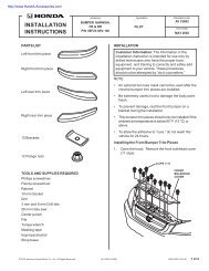
18. Install the suction hose <strong>and</strong> the discharge hose (compressor side).<br />
Route the discharge hose under the right side headlight.<br />
Remove <strong>and</strong><br />
discard the nut<br />
<strong>and</strong> cap.<br />
Discharge<br />
hose<br />
Remove <strong>and</strong><br />
discard the nut<br />
<strong>and</strong> cap.<br />
Install suction hose<br />
<strong>and</strong> new nut.<br />
Installation torque:<br />
9.8 N·m (7.2 lb-ft)<br />
Install discharge hose<br />
<strong>and</strong> new nut.<br />
Installation torque:<br />
9.8 N·m (7.2 lb-ft)<br />
Discharge<br />
hose<br />
Discharge<br />
hose<br />
© 2002 American Honda Motor Co., Inc - All Rights Reserved. AII 24107 (0212) 13 of 20
19. Reinstall the alternator.<br />
Re<strong>installation</strong> torque:<br />
8 N·m (6 lb-ft)<br />
Reinstall terminal <strong>and</strong> nut.<br />
Reconnect.<br />
Attach clip.<br />
Reinstall<br />
P/S<br />
pump.<br />
Reinstall two bolts.<br />
(M8x45mm)<br />
Re<strong>installation</strong> torque:<br />
24 N·m (18 lb-ft)<br />
20. Install the compressor belt.<br />
Reinstall the alternator.<br />
Reinstall three bolts.<br />
(2-M8x45mm)<br />
(1-M8x105mm)<br />
Re<strong>installation</strong> torque: 24 N·m (18 lb-ft)<br />
Apply pressure to the tool in this direction to loosen tensioner.<br />
Install tool<br />
Belt routing<br />
Install the new belt<br />
<strong>and</strong> route as shown.<br />
Remove tool <strong>and</strong><br />
confirm if the<br />
auto-tensioner<br />
is within<br />
specifications<br />
using the indicator.<br />
14 of 20 AII 24107 (0212) © 2002 American Honda Motor Co., Inc - All Rights Reserved.
21. Install the condenser fan.<br />
Reconnect reservoir hose.<br />
93403-06016-05<br />
6x16mm Gray<br />
Install the condenser fan<br />
on the radiator, <strong>and</strong> tighten<br />
the two new washer bolts.<br />
Re<strong>installation</strong> torque:<br />
9.8 N·m (7.2 lb-ft)<br />
Reinstall the<br />
reservoir <strong>and</strong><br />
position the tab<br />
as shown.<br />
Reinstall the bolt.<br />
Re<strong>installation</strong><br />
torque:<br />
9.8 N·m (7.2 lb-ft)<br />
Tab<br />
Pull the top of the<br />
radiator outward.<br />
22. Install the condenser.<br />
Install the<br />
suction pipe<br />
clamp “A”<br />
<strong>and</strong> new bolt.<br />
Installation<br />
torque:<br />
9.8 N·m<br />
(7.2 lb-ft)<br />
Position the right condenser bracket.<br />
Installation torque: 9.8 N·m (7.2 lb-ft)<br />
Install the<br />
discharge<br />
hose <strong>and</strong><br />
new bolt<br />
to the<br />
condenser.<br />
Installation<br />
torque:<br />
9.8 N·m<br />
(7.2 lb-ft)<br />
Position the condenser<br />
on the front lower frame.<br />
Install the receiver pipe “B” to<br />
the condenser, <strong>and</strong> tighten<br />
the new flange bolt.<br />
Re<strong>installation</strong> torque: 9.8 N·m (7.2 lb-ft)<br />
Position the left bracket<br />
on the condenser <strong>and</strong> install<br />
new bolt.<br />
Installation torque:<br />
9.8 N·m (7.2 lb-ft)<br />
“L” <strong>and</strong> “R” are indicated<br />
on brackets.<br />
© 2002 American Honda Motor Co., Inc - All Rights Reserved. AII 24107 (0212) 15 of 20
23. Connect the vehicle harness.<br />
Blue tape<br />
Connect the condenser fan motor<br />
connector to the vehicle harness.<br />
Untape (blue tape) the<br />
condenser fan motor connector.<br />
Remove <strong>and</strong> discard<br />
the protective cap.<br />
Untape (blue tape)<br />
the compressor<br />
magnetic clutch<br />
connector.<br />
Connect the compressor clutch<br />
connector to the vehicle harness,<br />
<strong>and</strong> attach the connector to the<br />
fan shroud.<br />
Remove <strong>and</strong><br />
discard the<br />
protective cap.<br />
Attach the harness<br />
clip to the fan shroud.<br />
24. Reinstall the bulkhead <strong>and</strong> upper radiator bracket.<br />
Reinstall the upper radiator brackets.<br />
Install two bolts.<br />
Installation torque:<br />
9.8 N·m (7.2 lb-ft)<br />
Install two bolts.<br />
Installation torque: 9.8 N·m (7.2 lb-ft)<br />
Reinstall the bulkhead.<br />
Install two bolts.<br />
Installation torque: 9.8 N·m (7.2 lb-ft)<br />
Install two bolts.<br />
Installation torque: 9.8 N·m (7.2 lb-ft)<br />
16 of 20 AII 24107 (0212) © 2002 American Honda Motor Co., Inc - All Rights Reserved.
25. Install the A/C pipe unit.<br />
Install new paint cutting nuts.<br />
Installation torque: 9.8 N·m<br />
(7.2 lb-ft)<br />
Remove the flange bolt, bracket,<br />
<strong>and</strong> disconnect the harness clip.<br />
Install the A/C pipe<br />
unit with new bolt<br />
to the evaporator.<br />
Installation torque:<br />
9.8 N·m (7.2 lb-ft)<br />
Attach clip.<br />
Attach pipe.<br />
Install the suction pipe clamp <strong>and</strong> new bolt.<br />
Installation torque: 9.8 N·m (7.2 lb-ft)<br />
26. Install the receiver pipe A.<br />
Install receiver pipe “A” <strong>and</strong> tighten loosely.<br />
Tighten flare nut.<br />
Installation torque: 13 N·m (9.5 lb-ft)<br />
Install receiver pipe “A” <strong>and</strong><br />
tighten loosely.<br />
Attach clip<br />
<strong>and</strong> pipe.<br />
Attach<br />
clip<br />
<strong>and</strong><br />
pipe.<br />
Untape (blue tape) the pressure<br />
switch connector, remove the<br />
protectice cap from the pressure<br />
switch, <strong>and</strong> connect the harness to<br />
the pressure switch.<br />
Attach clip<br />
<strong>and</strong> pipe.<br />
© 2002 American Honda Motor Co., Inc - All Rights Reserved. AII 24107 (0212) 17 of 20
27. Tighten the suction hose.<br />
Attach the suction pipe clamp <strong>and</strong> tighten<br />
the new washer bolt.<br />
Installation torque: 9.8 N·m (7.2 lb-ft)<br />
A/C pipe unit<br />
A/C<br />
pipe<br />
unit<br />
Tighten flare nut.<br />
Installation torque:<br />
31 N·m (23 lb-ft)<br />
Attach suction hose.<br />
A/C pipe<br />
unit<br />
28. Install the power relay.<br />
Remove the underhood fuse/relay box lid.<br />
Install the two power relays.<br />
18 of 20 AII 24107 (0212) © 2002 American Honda Motor Co., Inc - All Rights Reserved.
29. Attach the A/C label.<br />
Attach the A/C information label<br />
on the center of the hood.<br />
Attach the A/C kit label on<br />
the left side of the hood.<br />
30. Reinstall the removed engine room parts.<br />
o<br />
Check if completed.<br />
Removed parts<br />
o<br />
o<br />
o<br />
o<br />
o<br />
o<br />
o<br />
o<br />
o<br />
Bulkhead cover<br />
Front bumper<br />
Splash shield<br />
Power steering reservoir<br />
Bracket<br />
Main vehicle harness clamp<br />
Lid of the under-hood fuse/relay box<br />
Negative battery cable<br />
Reset the customer’s radio stations<br />
© 2002 American Honda Motor Co., Inc - All Rights Reserved. AII 24107 (0212) 19 of 20
20 of 20 AII 24107 (0212) © 2002 American Honda Motor Co., Inc - All Rights Reserved.