Download application note - FISO Technologies, Inc.
Download application note - FISO Technologies, Inc.
Download application note - FISO Technologies, Inc.

Create successful ePaper yourself
Turn your PDF publications into a flip-book with our unique Google optimized e-Paper software.
<strong>FISO</strong> offers unique<br />
instrumentation<br />
for EED testing<br />
TODAY’S TECHNOLOGICAL ADVANCES IN TELECOMMUNICATIONS<br />
HAVE YIELDED A NUMBER OF MORE AND MORE POWERFUL<br />
RADAR AND TRANSMITTER-RECEIVER SYSTEMS THAT EMANATE<br />
ELECTROMAGNETIC (EM) ENERGY AT HIGH LEVELS.<br />
Parallel to this development, is the trend to use more<br />
sensitive, low power electronic circuits in the design<br />
of electro-explosive devices (EEDs). EEDs are electrically<br />
initiated devices (EIDs) having an explosive or pyrotechnic<br />
output and they are activated by an electroexplosive<br />
initiator. EEDs are used in many industrial<br />
and civil <strong>application</strong>s such as fire extinguishers and automobile<br />
air bags, but the ones we shall discuss in this<br />
article are the ones related to military uses such as in<br />
aircraft and weapons systems.<br />
In military systems, EIDs perform a variety of functions,<br />
such as initiating rocket motors, arming and detonating<br />
warheads, and ejecting chaff and flares. By design,<br />
these devices can be susceptible to electromagnetic<br />
interference emanating mainly from the high-level<br />
EM energy communication devices that can accidentally<br />
activate the device and cause an unexpected detonation.<br />
The main problem with EEDs is what may result from<br />
the adverse interactions between the EME and the<br />
electrical initiators or initiating systems contained<br />
within ordnance systems. These hazards are referred<br />
to as HERO or Hazards of Electromagnetic Radiation<br />
to Ordnance and tests are required to measure the<br />
amount of energy developed in the EED circuits in order<br />
to insure against spontaneous and unwanted detonation<br />
while exercising the device’s electrical system<br />
and/or operating strong electrical fields.<br />
The US Department of Defense (DoD) has set forth in<br />
its reference document MIL-HDBK-240 all the information<br />
that is necessary to know to carry out HERO<br />
testing on EEDs, from the type of equipment to use,<br />
to the test procedure and reporting practices.<br />
by Saileth Ramírez, Technical Writer and Luc Langlois, Product Manager
Test Approach<br />
The general approach for HERO testing is to expose inert, instrumented<br />
ordnance to a controlled test EME and to monitor each<br />
EID contained within the ordnance for a possible response. For<br />
most EIDs, the response is quantified in terms of the magnitude<br />
of RF current induced into the heating element, or bridgewire,<br />
of the device.<br />
Instrumentation systems used in DoD HERO programs measure<br />
the temperature rise in the bridgewire of an EID from which the<br />
equivalent induced RF current may be inferred. The important<br />
parameter is not the amplitude of the induced RF current, but<br />
rather the effect of the current, which is to cause a rise in the<br />
temperature of the bridgewire. However, it has become the accepted<br />
practice for HERO testing to quantify the EID response in<br />
terms of current rather than temperature. This equivalent dc<br />
current is used as a convenient point of comparison to the EID’s<br />
statistical firing data that are usually given in terms of current.<br />
Recommended Test System<br />
EID instrumentation is unique for HERO testing. It appears to be<br />
rather simplistic to simply detect and monitor RF-induced responses<br />
of EIDs contained in an ordnance system. Yet, because<br />
HERO testing is complex and dynamic in nature, the instrumentation<br />
is also complex and very challenging. A typical HERO<br />
instrumentation system, as described in the military handbook,<br />
consists of four basic units:<br />
• A sensor to detect an RF-induced response.<br />
• A transmission line to carry the sensor data to a receiver<br />
or readout device.<br />
• A device to translate sensor data into desirable units<br />
of measurement.<br />
• A means of recording the data into a permanent record.<br />
In essence, the required instrumentation characteristics are<br />
as follows:<br />
• The sensor/transducer should be capable of detecting small<br />
changes in temperature in a device that has a small mass<br />
and, therefore, very little thermal energy associated with<br />
its temperature.<br />
• The instrumentation system, that is, sensor/transducer,<br />
monitoring, and recording devices, should be capable of<br />
detecting responses to short duration pulses or stimuli.<br />
• The sensor/transducer should not alter the firing and<br />
EM characteristics.<br />
• The instrumentation system should not alter the EM<br />
characteristics of the ordnance system under test.<br />
• The instrumentation system should not be adversely<br />
impacted or altered by the EME.<br />
• The instrumentation system should be capable of operating<br />
for the duration of the test.<br />
• The instrumentation package must be rugged, compact,<br />
and relatively simple to operate.<br />
However, the most important factor concerning the instrumentation<br />
is that it must be sensitive enough to establish the required<br />
pass/fail margin when the system is exposed to its expected operational<br />
EME.<br />
The instrumentation system should not be adversely affected by<br />
the EME. An all fiber-optic based system from sensor to receiver/<br />
recorder such as the Veloce 100 is the preferred instrumentation<br />
method of ordnance for HERO testing.<br />
Test Sensors<br />
There are a variety of sensors and transducers used to detect and<br />
measure ohmic heating of bridge wire-type EIDs. However, optical,<br />
sensor-based instrumentation systems are preferred over<br />
conductive-type sensor instrumentation systems because the<br />
potential impact on the ordnance system’s RF characteristics is<br />
eliminated by the use of non-conductive instrumentation leads.<br />
Some sensors are attached to or are in direct contact with, the<br />
EID’s bridgewire. Others are positioned near the bridgewire (for<br />
example, within 0.003 inches). Non-conductive sensors (opticalbased)<br />
can be placed in direct contact with or be attached to the<br />
bridgewire without altering its inherent electrical and EM characteristics.<br />
In addition, the position of the sensor/bridgewire is<br />
more stable and is less likely to change under environmental<br />
stress. The conductive-type sensors are not normally attached to,<br />
or in contact with, the bridgewire. Special care must be taken<br />
during the sensor installation process to ensure that the conductive<br />
sensor is correctly positioned and that it is secured in place<br />
so that its position does not change under environmental stress.<br />
The basic steps for instrumenting ordnance for HERO tests are<br />
to minimize both the disturbance to the EM energy created by<br />
the instrumentation package and the coupling of the RF energy<br />
to the data channels. The instrumentation package should be<br />
small and internal to the ordnance item under test. Optical telemetry<br />
techniques may be used to reduce coupling of RF energy<br />
into the signal leads. Extreme care must be exercised to ensure<br />
that the instrumentation provides an accurate measurement of<br />
the voltage, current, or other response without significantly<br />
changing the test results. Instrumentation methods involving<br />
fiber-optic sensors and cables are used, almost exclusively, to<br />
achieve accurate, unperturbed measurements.<br />
Safe EED Testing by <strong>FISO</strong><br />
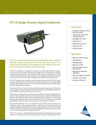
The FOT-HERO sensor and the VELOCE-100 signal conditioner<br />
have been specifically developed for Hazardous Electromagnetic<br />
Radiation Ordnance (HERO) testing of electrical shielding and<br />
electromagnetic compatibility (EMC). The fiber optic temperature<br />
sensor can be mounted in the EED, is immune to EMI, operates<br />
in real time, has a fast response time and is extremely sensitive.<br />
With its tiny size of 150 microns and its low thermal mass, the<br />
thermal transfer from the source to the FOT-HERO sensor is almost<br />
instantaneous.<br />
Since the FOT-HERO sensor is based in fiber-optics technology, it<br />
is inherently EME inert.<br />
The FOT-HERO sensor provides, by design, an extremely fast response<br />
time, better than 275 milliseconds (defined as the rise<br />
time from 10% to 90% of the output, based on MK1 squib).<br />
Independently of the squib, the sensor response time is better<br />
than 1 millisecond. Its sensitivity is very high, also by design.<br />
Depending on the <strong>application</strong>, the squib and the test conditions,<br />
sensitivity could be of 3 mA and better.
The Veloce-100 system combined with the FOT-HERO sensor offers<br />
the unique reference instrumentation for EED safety testing.<br />
The system enables real time monitoring of EEDs while these<br />
devices are bombarded by electromagnetic fields. The FOT-HERO<br />
sensor is available bare, ready for field installation, or already<br />
mounted on a squib.<br />
The principle of the Veloce 100 system is based on a Fabry-Perot<br />
interferometer. The signal conditioner contains a light source<br />
and a detector. For each slide-in module, the detector and light<br />
source are internally combined on one fiber optic line by a coupler<br />
and routed to the conditioner front plate, where fiber optic<br />
sensor is connected using a highly stable ST type fiber optic connector.<br />
The use of an extension cable is also possible. The system<br />
can reach as high as 200 kHz in sampling rate and is capable of<br />
averaging results, as required by the tests.<br />
Sample Application<br />
A typical <strong>application</strong> for the Veloce 100 and the FOT-HERO sensor<br />
is determining the optimum distance between two army tanks<br />
and a decoy launcher so as not to cause any interference between<br />
them that may accidentally activate any EID.<br />
Thanks to the system, the army was able to determine that the<br />
minimum distance allowable was far closer than the currently<br />
established restriction.<br />
The army runs tactical evaluation (Tac Eval) maneuvers that require<br />
army vehicles to operate in close proximity to where decoy<br />
launchers are loaded and unloaded from helicopters. Decoy<br />
launchers employ either CCU-41B (chaff activator) or CCU-136A<br />
(flare activator) cartridges. Previous lab testing had revealed<br />
some susceptibilities in the cartridges so a restriction in distance<br />
of 50 meters for any VHF radio was in place. This restriction would<br />
have considerably hampered the Tac Eval. Therefore, QETE was<br />
called in to see if the restrictions could be eased.<br />
Utilizing <strong>FISO</strong> equipment, the cartridges were instrumented and<br />
the appropriate chaff and flares modified to re-create the actual<br />
installation as close as possible.<br />
Test Setup<br />
The test consisted on tuning in specific frequencies at a given<br />
power and distance. If a detonation occurred, the distance would<br />
be increased until a safe margin was attained.<br />
Four instrumented cartridges of each type were inserted into the<br />
decoy launcher with its flares/chaff and vehicles were placed on<br />
either side of the launcher with a separation distance (launcher<br />
to vehicle) of 5, 10 or 20 meters. A total of 50 test runs were<br />
made, 25 for each cartridge/decoy combination.<br />
The series of test Frequencies (in MHz) employed was:<br />
1) 33.2 3) 35.0 5) 41.1 7) 44.6<br />
2) 34.9 4) 39.8 6) 42.4 8) 45.7<br />
Measurement Method<br />
For each test, the current was measured and recorded for a full<br />
20 seconds. The transmitter was not activated until the 5-second<br />
mark to give an indicator if any current change on the bridge<br />
wire occurred (even minor – down to about 8 mA).<br />
Conclusions<br />
After executing the series of tests at 5 meters from the launcher<br />
without recording any significant disturbances, it was deemed<br />
unnecessary to proceed with the test at longer distances. It was<br />
also determined that little to no risk exists with the radios and<br />
frequencies tested, as long as the radios used in the TACEVAL<br />
operate in a similiar frequency range and are not of significantly<br />
greater power.<br />
The Veloce 100 system helped in specifying that if VHF frequencies<br />
are below 50 MHz and radios are not of significantly greater<br />
power output, reduction of operational restriction distances from<br />
50 m to 5 m should be acceptable.
<strong>FISO</strong> <strong>Technologies</strong> <strong>Inc</strong>.<br />
500 St-Jean-Baptiste Ave., suite 195<br />
Québec (Québec)<br />
Canada G2E 5R9<br />
Phone (418) 688-8065<br />
Fax (418) 688-8067<br />
Email<br />
info@fiso.com<br />
support@fiso.com<br />
Web<br />
www.fiso.com<br />
APN-EED-AN-2005-09-50