Lecture 6 Auto-Transformers
Lecture 6 Auto-Transformers
Lecture 6 Auto-Transformers

You also want an ePaper? Increase the reach of your titles
YUMPU automatically turns print PDFs into web optimized ePapers that Google loves.
<strong>Lecture</strong> 6<br />
<strong>Auto</strong>-<strong>Transformers</strong><br />
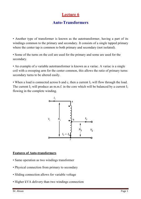
• Another type of transformer is known as the autotransformer, having a part of its<br />
windings common to the primary and secondary. It consists of a single tapped primary<br />
where the center tap is common to both primary and secondary (not isolated).<br />
• Some of the turns on the coil are used for the primary and some are used for the<br />
secondary.<br />
• An example of a variable autotransformer is known as a variac. A variac is a single<br />
coil with a sweeping arm for the center common, this allows the ratio of primary turns:<br />
secondary turns to be altered easily.<br />
• When a load is connected across b and c, then a current I 2 will flow through the load.<br />
The current I 2 will produce an m.m.f. in the core which will be balanced by a current I 1<br />
flowing in the complete winding.<br />
Features of <strong>Auto</strong>-transformers<br />
• Same operation as two windings transformer<br />
• Physical connection from primary to secondary<br />
• Sliding connection allows for variable voltage<br />
• Higher kVA delivery than two windings connection<br />
Dr. Ahsan Page 1
The voltages and currents are related by the same turns-ratio as in a two-winding<br />
transformer:<br />
V1 N1 I1 N2<br />
1<br />
a; ; I N I N<br />
V N I N a<br />
2 2 2 1<br />
Example:<br />
1 1 2 2<br />
A single-phase, 100 kVA, 2000/200V, two winding transformer is connected as an<br />
autotransformer to supply a load at 2200V from a 2000V supply. Calculate the<br />
following:<br />
a) kVA rating as an autotransformer<br />
b) Apparent power transferred by electromagnetic induction<br />
c) Apparent power transferred by conduction<br />
d) If the total losses of the two-winding transformer at full-load is 1450 W, find<br />
the efficiency of the auto-transformer operating at full-load and 0.8 pf lagging.<br />
Solution:<br />
The single-phase, two-winding transformer is reconnected as an autotransformer as<br />
shown in Fig below. The current ratings of the windings are given by<br />
The current ratings of the windings<br />
are:<br />
I<br />
I<br />
ab<br />
bc<br />
100,000<br />
500A<br />
200<br />
100,000<br />
50A<br />
2000<br />
Therefore, for full-load operation of the autotransformer, the terminal currents are:<br />
I H = 500 A ;<br />
I L = (500+50) = 550 A<br />
Now, V L = 2000 V, V H = (2000 + 200) = 2200 V<br />
Dr. Ahsan Page 2
Therefore, the kVA rating of the autotransformer is:<br />
kVA<br />
kVA<br />
L<br />
H<br />
2000550 1100 kVA<br />
1000<br />
2200500 1100 kVA<br />
1000<br />
(b) The apparent power transferred by induction: S indction = 100 kVA<br />
(c) The apparent power transferred by conduction: S condction = 1100 – 100 = 1000 kVA<br />
(d) The output of the auto-transformer:<br />
( )<br />
Considering transformer losses remains same, the efficiency is given by:<br />
Pout<br />
Pout<br />
880,000 <br />
100% 100% 100% 99.83%<br />
P P P<br />
<br />
880,000 1450<br />
<br />
<br />
<br />
in out loss<br />
Advantages of <strong>Auto</strong>-transformer<br />
• It effects a saving in winding material (copper or aluminum), since the secondary<br />
winding is part of the primary current.<br />
• Lower copper loss, therefore efficiency is higher than in the two winding<br />
transformer.<br />
• Lower leakage reactances, lower exciting current.<br />
• Variable output voltage can be obtained.<br />
Disadvantages of <strong>Auto</strong>-Transformer<br />
• There is a direct connection between the primary and secondary sides.<br />
• Should an open-circuit develop between points b and c, the full mains voltage would<br />
be applied to the secondary.<br />
• The short-circuit current is much larger than for normal two-winding transformer<br />
Dr. Ahsan Page 3