Solaris LPG conversion instructions.pdf - Heatline
Solaris LPG conversion instructions.pdf - Heatline
Solaris LPG conversion instructions.pdf - Heatline

You also want an ePaper? Increase the reach of your titles
YUMPU automatically turns print PDFs into web optimized ePapers that Google loves.
solaris<br />
lpg <strong>conversion</strong><br />
solaris lpg <strong>conversion</strong>
solaris lpg <strong>conversion</strong><br />
Conversion Instructions for the <strong>Solaris</strong> 24 & 30PC, & 24 & 30PCS<br />
Warning: The <strong>conversion</strong> must be carried out by a competent person as described in the<br />
Gas Safety (Installation and Use) Regulations.<br />
If gas <strong>conversion</strong> is required (from NG to <strong>LPG</strong> etc.), follow the <strong>instructions</strong> below using<br />
only approved components from your agent:<br />
<br />
<br />
<br />
A flue gas analyser must be used when making any adjustments that can affect the<br />
combustion characteristics of the boiler. (this includes converting to a different gas<br />
type )<br />
Remove the outer case and sealed inner door, refer to boiler <strong>instructions</strong> if required.<br />
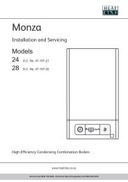
Fit the new air/gas mixer ring after disconnecting the gas pipe from the gas valve (see<br />
figure below (red)).<br />
01<br />
<br />
Adjust dip switch 1 to the “On” position for <strong>LPG</strong>, “Off” for NG, on the main circuit<br />
board which is accessible after opening the control box.<br />
POTENTIOMETERS<br />
DIP SWITCHES<br />
P7<br />
P5<br />
P2<br />
P4<br />
Change the diaphragm, which is located in the outlet of the gas valve. (<strong>LPG</strong> 24kW -<br />
4.7mm, <strong>LPG</strong> 30kW - 5.35mm, NG 24kW – 6.5, NG 30kW – 7.0mm)<br />
Page 1 of 3
solaris lpg <strong>conversion</strong><br />
<br />
<br />
<br />
<br />
Once re-assembly of the gas circuit check for gas soundness.<br />
Set the CO 2 as described below noting the correct CO 2 value for the type of gas that<br />
will be used, 9.0 +/-0.1% NG and 10.0 +/-0.1% <strong>LPG</strong>.<br />
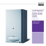
Insert a combustion analyser into the socket on the flue adapter.<br />
Remove the brass screw to access the zero adjustment socket.<br />
Feedback<br />
silicone pipe<br />
Zero adjustment<br />
socket (4mm allen<br />
key)<br />
Pressure Test point<br />
02<br />
<br />
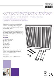
Turn the boiler's function switch “4” as shown below to the ‘heating/hot water’<br />
position.<br />
5<br />
1<br />
2<br />
3<br />
4<br />
1- Timer 4- Function switch<br />
2- D.H.W. temperature control 5- LCD display<br />
3- C/Heating temperature control<br />
Page 2 of 3
solaris lpg <strong>conversion</strong><br />
<br />
<br />
<br />
Turn the central heating temperature control “2 above” to maximum setting.<br />
Turn Potentiometers P2 & P4 (figure 19) anticlockwise to the minimum setting.<br />
Using a 4mm allen key adjust clockwise: to increase the CO 2 setting, anticlockwise:<br />
to decrease the CO 2 setting by means of a 4mm allen key. (Natural Gas 9%, <strong>LPG</strong><br />
10%)<br />
After adjustment, insert the brass screw and re-set the potentiometers as follows P7,<br />
P2 & P4 to 4 o’clock, P5 min.<br />
<br />
Check for correct boiler operation.<br />
Important.<br />
Gas type <strong>conversion</strong> must be completed by attaching the labels included<br />
in the gas <strong>conversion</strong> kit to the boiler.<br />
• Type of gas label – (Yellow) in a visible position inside the boiler.<br />
• Grey label – to cover the existing gas type on the data plate.<br />
• Instruction label – Inside drop down cover on the front of the boiler.<br />
03<br />
Page 3 of 3
<strong>Heatline</strong><br />
Nottingham Road,<br />
Belper,<br />
Derbyshire,<br />
DE56 1JT<br />
Tel: 01773 596 099<br />
Fax: 01773 828 123<br />
Email: sales@heatline.co.uk