Monza 24 and 28 Instructions for use - Heatline
Monza 24 and 28 Instructions for use - Heatline
Monza 24 and 28 Instructions for use - Heatline

Create successful ePaper yourself
Turn your PDF publications into a flip-book with our unique Google optimized e-Paper software.
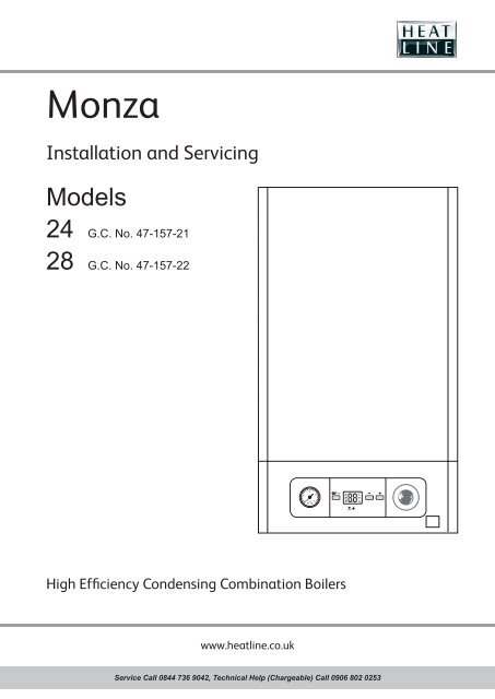
<strong>Monza</strong><br />
Installation <strong>and</strong> Servicing<br />
Models<br />
<strong>24</strong> G.C. No. 47-157-21<br />
<strong>28</strong> G.C. No. 47-157-22<br />
1<br />
2<br />
3<br />
mode<br />
0<br />
bar<br />
4<br />
reset<br />
High Efficiency Condensing Combination Boilers<br />
www.heatline.co.uk<br />
Service Call 0844 736 9042, Technical Help (Chargeable) Call 0906 802 0253
Guarantee Registration<br />
Thank you <strong>for</strong> installing a new <strong>Heatline</strong> appliance in your home.<br />
<strong>Heatline</strong> appliances are manufactured to the very highest st<strong>and</strong>ard so we are pleased to offer our customers<br />
a Comprehensive Guarantee. For the manufacturer's warranty to be valid, the Benchmark Log Book must<br />
be correctly completed by a suitably qualifi ed person <strong>and</strong> be available <strong>for</strong> inspection prior to any repair.<br />
Comprehensive Warranty, Terms <strong>and</strong> Conditions are available from: heatline@tfstore.co.uk or by calling<br />
01773 596013. We recommend you complete <strong>and</strong> return as soon as possible your guarantee registration<br />
card. If your guarantee registration card is missing you can obtain a copy or record your registration by<br />
telephoning the <strong>Heatline</strong> Customer Service number 0844 736 9042.<br />
Customer Service: 0844 736 9042<br />
Technical Helpline (Chargeable): 0906 802 0253<br />
For Complaints please contact:<br />
Customer Care, Group Service, Nottingham Rd.,<br />
Belper, Derbyshire<br />
DE56 1JL<br />
Benchmark places responsibilities on both manufacturers <strong>and</strong> installers. The purpose is to ensure that customers are provided<br />
with the correct equipment <strong>for</strong> their needs, that it is installed, commissioned <strong>and</strong> serviced in accordance with the manufacturer’s<br />
instructions by a competent person approved at the time by the Health <strong>and</strong> Safety Executive <strong>and</strong> that it meets the requirements of the<br />
appropriate Building Regulations. The Benchmark Checklist can be <strong>use</strong>d to demonstrate compliance with Building Regulations <strong>and</strong><br />
should be provided to the customer <strong>for</strong> future reference.<br />
Installers are required to carry out installation, commissioning <strong>and</strong> servicing work in accordance with the Benchmark Code of Practice<br />
which is available from the Heating <strong>and</strong> Hotwater Industry Council who manage <strong>and</strong> promote the Scheme.<br />
Visit www.central heating.co.uk <strong>for</strong> more in<strong>for</strong>mation.
INTRODUCTION<br />
1 <strong>Instructions</strong> guidance<br />
We recommend you complete <strong>and</strong> return as soon as possible<br />
your guarantee registration card. If your guarantee registration<br />
card is missing you can obtain a copy or record your registration<br />
by telephoning the <strong>Heatline</strong> Customer Service number 0844 736<br />
9042.<br />
1.1 Product documentation<br />
The instructions are an integral part of the appliance <strong>and</strong> must<br />
be h<strong>and</strong>ed to the <strong>use</strong>r on completion of the installation in order<br />
to comply with the current regulations.<br />
• Carefully read <strong>and</strong> underst<strong>and</strong> the manual, which will enable<br />
you to complete your task of installing or servicing this<br />
appliance safely. No liability can be accepted in the event of<br />
damage <strong>for</strong> not complying with the guidance in this instruction<br />
manual.<br />
These instructions consist of, Installation, Servicing, Fault Finding,<br />
Replacement of Parts <strong>and</strong> Spares. The instructions are an integral<br />
part of the appliance <strong>and</strong> must, to comply with the current issue of<br />
the Gas Safety (Installation <strong>and</strong> Use) Regulations, be h<strong>and</strong>ed to the<br />
<strong>use</strong>r on completion of the installation.<br />
1.2 Associated documents<br />
- 1 magnetic lighting instruction label<br />
- 1 guarantee envelope pack<br />
- 1 wall template<br />
1.3 Explanation of symbols<br />
a<br />
DANGER:<br />
e<br />
DANGER:<br />
Risk of injury.<br />
Risk of electric shock.<br />
ATTENTION: Risk of damage to the appliance or<br />
to its surroundings.<br />
IMPORTANT: Important in<strong>for</strong>mation.<br />
1.4 Guarantee registration<br />
Thank you <strong>for</strong> installing a new <strong>Heatline</strong> appliance in your home.<br />
<strong>Heatline</strong> appliances are manufactured to the very highest<br />
st<strong>and</strong>ard so we are pleased to offer our customers a<br />
Comprehensive 12 month Guarantee, with the option to extend it<br />
to two years.<br />
2 Appliance description<br />
2.1 Safety devices<br />
Overheating Safety Device<br />
The appliance is designed to recognise the potential of an<br />
overheat situation <strong>and</strong> will shutdown be<strong>for</strong>e a potentially<br />
dangerous situation occurs.<br />
Safety discharge valve<br />
A safety discharge valve <strong>and</strong> discharge pipe are fi tted to the<br />
boiler. This valve must not be touched.<br />
- The heating safety valve opens when the pressure in the<br />
heating circuit exceeds 3bar.<br />
• Should there be any discharge from the pipe, which should<br />
terminate in a safe place outside the property, isolate the<br />
boiler’s electrical supply <strong>and</strong> call your Installer, Service<br />
Engineer or <strong>Heatline</strong>’s Service Department.<br />
Frost protection<br />
The appliance has a built in frost protection device that protects<br />
the boiler from freezing. With the gas <strong>and</strong> electric supplies<br />
ON <strong>and</strong> irrespective of any room thermostat setting, the frost<br />
protection device will operate the pump when the temperature of<br />
the boiler water falls below 8 O C.<br />
A timer is <strong>use</strong>d so that the temperature can be checked<br />
periodically. After 10 minutes the pump will be stopped if the<br />
temperature is higher than 10 O C or has already reached 35 O C.<br />
The burner will activate if the boiler temperature does not reach<br />
10 O C after 30 minutes or at any time if the temperature drops to<br />
5 O C.<br />
The burner will switch off when the temperature reaches 35 O C.<br />
The frost-protection system is active when the appliance is<br />
switched on.<br />
The boiler controls cannot ensure that the installation is<br />
fully protected against frost. Any exposed pipes should be<br />
adequately protected <strong>and</strong> particular attention should be paid to<br />
condensate drains. An additional frost thermostat may also be<br />
required.<br />
a<br />
Your<br />
domestic water circuit (hot or cold) is not<br />
protected by the boiler controls.<br />
Condensate drain blockage<br />
During freezing conditions this may be due to the <strong>for</strong>ming of<br />
ice in the condense drain external to the ho<strong>use</strong>. In this case, a<br />
safety device shuts down the appliance.<br />
Service Call 0844 736 9042, Technical Help (Chargeable) Call 0906 802 0253<br />
- 3 -
2.2 Data label<br />
The data label certifi es the country where the appliance is<br />
intended to be installed. It is located on the rear of the drop<br />
down control box<br />
The data label contains the following data:<br />
- The name of the manufacturer<br />
- The country of intended destination<br />
- The commercial name of the appliance <strong>and</strong> its serial number<br />
- The types of fl ue installations authorised<br />
- The appliance's gas category<br />
Product/production certifi ed by:<br />
Notifi ed body IMQ 52BP2727 CE Directives 2009/142/EEC.<br />
52BP27<strong>28</strong>DR CE Directives 92/42/EEC.<br />
The CE mark indicates that the appliances described in this<br />
manual are in compliance with the following directives:<br />
- European directive n°2009-142 relative to gas appliances<br />
- European directive n°2004-108 from the European Parliament<br />
<strong>and</strong> Council relative to electromagnetic compatibility<br />
- European directive n°2006-95 from the European Parliament<br />
<strong>and</strong> Council relative to low voltage<br />
- European directive n°92-42 relative to the yield of boilers<br />
- The gas type, group <strong>and</strong> pressure, set in the factory<br />
- The DHW specifi c fl ow rate (D)<br />
- The maximum pressure in the heating circuit (PMS)<br />
- The maximum pressure in the domestic water circuit (PMW)<br />
- The NOx class of the appliance<br />
- The type <strong>and</strong> voltage of electricity supply<br />
- The maximum power rating<br />
- The electrical protection class<br />
- The minimum <strong>and</strong> maximum heat input (Q)<br />
- The minimum <strong>and</strong> maximum power output (P)<br />
- The CE number <strong>and</strong> logo<br />
a<br />
The appliance shall only be connected to the gas<br />
type(s) indicated on the data label.<br />
2.3 Gas category<br />
This boiler is <strong>for</strong> <strong>use</strong> only on G20, but can be converted <strong>for</strong> <strong>use</strong><br />
on G31.<br />
• To adapt the appliance to another type of gas, see the<br />
chapter "Gas conversion".<br />
2.4 Regulation <strong>and</strong> statutory requirements<br />
CE Mark<br />
This boiler meets the requirements of Statutory Instrument,<br />
No. 3083 The Boiler (Effi ciency) Regulations, <strong>and</strong> there<strong>for</strong>e is<br />
deemed to meet the requirements of Directive 92/42/EEC on the<br />
effi ciency requirements <strong>for</strong> new hot water boilers fi red with liquid<br />
or gaseous fuels.<br />
Type test <strong>for</strong> purposes of Regulation 5 certifi ed by:<br />
Notifi ed body IMQ 52BP2727 CE Directives 2009/142/EEC.<br />
52BP27<strong>28</strong>DR CE Directives 92/42/EEC.<br />
2.5 Hydraulic schematic<br />
13<br />
12<br />
11<br />
10<br />
9<br />
8<br />
7<br />
23<br />
6<br />
5<br />
3<br />
2<br />
1<br />
Key<br />
1 Gas service isolating valve (Yellow)<br />
2 Heating flow isolating valve (Red)<br />
3 Heating safety valve<br />
4 N/A<br />
5 DHW flow sensor<br />
6 Domestic plate to plate heat exchanger<br />
7 By-pass<br />
8 Heating return thermistor (Blue)<br />
9 Condensate trap<br />
10 Ignition <strong>and</strong> control electrode<br />
11 Burner<br />
12 Main heat exchanger<br />
13 Thermal f<strong>use</strong><br />
14 Flue outlet<br />
15 Silencer<br />
16 Heating expansion vessel<br />
17 Fan<br />
18 Gas control valve<br />
14<br />
15<br />
16<br />
17<br />
18<br />
19<br />
20<br />
21<br />
22<br />
<strong>24</strong><br />
25<br />
26<br />
27<br />
- 4 - Service Call 0844 736 9042, Technical Help (Chargeable) Call 0906 802 0253
19 Ignition module<br />
20 Heating flow thermistor (Red)<br />
21 Air vent<br />
22 Pump<br />
23 Three way valve<br />
<strong>24</strong> Water pressure sensor<br />
25 Heating return isolating valve <strong>and</strong> filter (Blue)<br />
26 Domestic cold water isolating valve <strong>and</strong> filter (Blue)<br />
27 Domestic hot water outlet valve<br />
A Heating flow<br />
B Domestic hot water outlet<br />
C Pipe <strong>for</strong> heating safety valve<br />
D Gas inlet<br />
E Cold water inlet<br />
F Heating return<br />
G Condensate drain<br />
3 Safety instructions <strong>and</strong> regulations<br />
3.1 Safety instructions<br />
If the gas pressure at the input of the appliance is outside the<br />
range specifi ed, the appliance must not be put into operation.<br />
e<br />
Incorrect<br />
installation can ca<strong>use</strong> electric shock or<br />
appliance damage.<br />
• Never disable safety devices <strong>and</strong> do not try to adjust them.<br />
With regards to the “Manual H<strong>and</strong>ling Operations, 1992<br />
Regulations”, the appliance exceeds the recommended weight<br />
<strong>for</strong> a one person lift.<br />
The h<strong>and</strong>ling of the boiler may involve lifting, pushing <strong>and</strong><br />
pulling, the <strong>use</strong> of a sack truck may be required.<br />
• Note this appliance is heavy <strong>and</strong> it is recommended that two<br />
people are required to lift the boiler.<br />
• Be sure to consider the following h<strong>and</strong>ling techniques <strong>and</strong><br />
precautions:<br />
- Grip the appliance at its base<br />
- Use safety clothing where appropriate, e.g. gloves, safety<br />
footwear.<br />
• Ensure safe lifting techniques are <strong>use</strong>d:<br />
- Keep back straight.<br />
- Avoid twisting at the waist.<br />
- Avoid upper body/top heavy bending.<br />
- Always grip using the palm of the h<strong>and</strong>.<br />
- Keep load as close to body as possible.<br />
- Always <strong>use</strong> assistance if required.<br />
• Under no circumstances must the <strong>use</strong>r interfere with or adjust<br />
sealed parts.<br />
• When assembling the connections, correctly position the<br />
seals to avoid any leakage of gas or water.<br />
• This appliance contains metal parts (components) <strong>and</strong> care<br />
should be taken when h<strong>and</strong>ling <strong>and</strong> cleaning, with particular<br />
regard to edges.<br />
The basic safety instructions must be followed be<strong>for</strong>e attempting<br />
to maintain or replace spare parts:<br />
• Electrically isolate the appliance from the power supply.<br />
• Turn off the appliance gas isolation valve.<br />
• Hydraulically isolate the appliance using the isolation valves<br />
below the boiler.<br />
• Protect all the electrical components from water while working<br />
on the appliance.<br />
• Mop up any spillage of water within the boiler.<br />
• Use only original spare parts.<br />
• Use only new O-rings <strong>and</strong> gaskets.<br />
• After having completed work on gas or water carrying<br />
components, check <strong>for</strong> their tightness.<br />
• When work on the appliance is completed, per<strong>for</strong>m an<br />
operational test <strong>and</strong> check <strong>for</strong> safety.<br />
3.2 Statutory requirements<br />
IMPORTANT<br />
Where no British St<strong>and</strong>ards exists, materials <strong>and</strong> equipment<br />
should be fi t <strong>for</strong> their purpose <strong>and</strong> of suitable quality <strong>and</strong><br />
workmanship.<br />
The installation of this boiler must be carried out by a competent<br />
person approved at the time by the Health <strong>and</strong> Safety Executive<br />
<strong>and</strong> in accordance with the rules in <strong>for</strong>ce in the Countries of<br />
installation.<br />
Manufacturer’s instructions must not be taken as overriding<br />
statutory requirements.<br />
Statutory Requirements<br />
In GB, the installation of the boiler must comply with the<br />
requirements of the current issue of BS6798 <strong>and</strong> be carried out<br />
by a competent person approved at the time by the Health <strong>and</strong><br />
Safety Executive <strong>and</strong> as described in the following regulations:<br />
- The manufacturer’s instructions supplied.<br />
- The Gas Safety (Installation <strong>and</strong> Use) Regulations.<br />
- The appropriate Buildings Regulations either The Building<br />
Regulations, The Building Regulations (Scotl<strong>and</strong>), The Building<br />
Regulations (Northern Irel<strong>and</strong>).<br />
- The Water Supply (water fi ttings) Regulations 1999 <strong>and</strong> water<br />
byelaws 2000, Scotl<strong>and</strong>.<br />
- The Health <strong>and</strong> Safety at Work Act, Control of Substances<br />
Hazardous to Health (COSHH).<br />
- The Current I.E.E. Wiring Regulations.<br />
Where no specifi c instructions are given, reference should be<br />
made to the relevant British St<strong>and</strong>ard Code of Practice.<br />
Service Call 0844 736 9042, Technical Help (Chargeable) Call 0906 802 0253<br />
- 5 -
In IE, the installation must be carried out by a competent person<br />
approved at the time by the Health <strong>and</strong> Safety Executive <strong>and</strong><br />
installed in accordance with the current edition of I.S.813<br />
“Domestic Gas Installations”, the current Building Regulations<br />
<strong>and</strong> reference should be made to the current ETCI rules <strong>for</strong><br />
Electrical Installation.<br />
GB: the following Codes of Practice apply: BS4814, BS6798,<br />
BS5440 Part 1 <strong>and</strong> 2, BS5546 Part 1, BS5449, BS6891,<br />
BS6700, BS7074 Part 1 <strong>and</strong> 2, BS7593, BS7671.<br />
IE: I.S.813, BS5546, BS 5449, BS 7074, BS 7593.<br />
NOTE: For further in<strong>for</strong>mation, see the current issue of the<br />
Building Regulations, approved document L1 ( in the UK) <strong>and</strong><br />
the following current issues of:<br />
1) Central heating system specifi cation (CheSS) <strong>and</strong><br />
2) Controls <strong>for</strong> domestic central heating system <strong>and</strong> hot water.<br />
BRECSU.<br />
Gas Supply<br />
The gas installation must be in accordance with the relevant<br />
st<strong>and</strong>ards.<br />
In GB, this is BS6891.<br />
In IE, this is the current edition of I.S.813 “Domestic Gas<br />
Installations”.<br />
The supply from the governed meter to the boiler must be a<br />
minimum of 22mm diameter <strong>and</strong> provide a steady inlet working<br />
pressure of 20mbar (8in wg) at the boiler. On completion, test<br />
the gas installation <strong>for</strong> tightness using the pressure drop method<br />
<strong>and</strong> suitable leak detection fl uid, purge in accordance with the<br />
above st<strong>and</strong>ard.<br />
Domestic Hot Water<br />
All domestic hot water circuits, connections, fi ttings must be<br />
in accordance with the relevant st<strong>and</strong>ards <strong>and</strong> water supply<br />
regulations.<br />
GB: Guidance G17 to G<strong>24</strong> <strong>and</strong> recommendation R17 to R<strong>24</strong> of<br />
the Water Regulations Guide.<br />
IE: The current edition of I.S.813 “Domestic Gas Installations”.<br />
Heating System<br />
In GB, it is necessary to comply with the Water Supply (Water<br />
Fittings) Regulations 1999 (<strong>for</strong> Scotl<strong>and</strong>, the Water Byelaws<br />
2000, Scotl<strong>and</strong>). To comply with the Water regulations your<br />
attention is drawn to: The Water Regulations guide published<br />
by the Water Regulations Advisory Service (WRAS) gives full<br />
details of the requirements.<br />
In IE, the requirements given in the current edition of I.S.813<br />
“Domestic Gas Installations” <strong>and</strong> the current Building<br />
Regulations must be followed.<br />
Electrical Supply<br />
The boiler MUST be earthed. All system components shall<br />
be of an approved type <strong>and</strong> all wiring to current I.E.E. wiring<br />
regulations. External wiring must be correctly earthed, polarised<br />
<strong>and</strong> in accordance with the relevant st<strong>and</strong>ards.<br />
In GB, this is BS 7671.<br />
In IE, this is the current edition of ETCI rules.<br />
The boiler MUST be connected to a permanent 230V ac, 50Hz<br />
supply.<br />
Connection of the whole electrical system of the boiler, including<br />
any heating controls, to the electrical supply MUST be through<br />
one common isolator <strong>and</strong> must be f<strong>use</strong>d 3 Amp maximum.<br />
Isolation should be by a double pole switched f<strong>use</strong>d spur box,<br />
with a minimum gap of 3mm <strong>for</strong> both poles. The f<strong>use</strong>d spur<br />
box should be readily accessible <strong>and</strong> preferably adjacent to the<br />
appliance. It should be identifi ed as to its <strong>use</strong>.<br />
Alternatively connection can be made through an unswitched<br />
shuttered socket <strong>and</strong> 3A f<strong>use</strong>d 3-pin plug both to the current<br />
issue of BS 1363, provided they are not <strong>use</strong>d in a room<br />
containing a bath or shower.<br />
Wiring to the boiler must be PVC 85 O C insulated cable, not less<br />
than 0.75mm 2 (<strong>24</strong>/0.20mm).<br />
3.3 Other regulations<br />
Gas Safety (Installation <strong>and</strong> Use) Regulations<br />
In your own interests <strong>and</strong> that of safety, it is the Law that ALL<br />
gas appliances are installed by a competent person approved at<br />
the time by the Health <strong>and</strong> Safety Executive in accordance with<br />
the current issue of these regulations.<br />
Control of Substances Hazardous to Health<br />
Under Section 6 of The Health <strong>and</strong> Safety at Work Act 1974, we<br />
are required to provide in<strong>for</strong>mation on substances hazardous to<br />
health. The adhesives <strong>and</strong> sealants <strong>use</strong>d in this appliance are<br />
cured <strong>and</strong> give no known hazard in this state.<br />
Insulation Pads:<br />
These can ca<strong>use</strong> irritation to skin, eyes <strong>and</strong> the respiratory tract.<br />
If you have a history of skin complaint you may be susceptible to<br />
irritation. High dust levels are usual only if the material is broken.<br />
Normal h<strong>and</strong>ling should not ca<strong>use</strong> discom<strong>for</strong>t, but follow normal<br />
good hygiene <strong>and</strong> wash your h<strong>and</strong>s be<strong>for</strong>e eating, drinking or<br />
going to the lavatory.<br />
• If you do suffer irritation to the eyes or severe irritation to the<br />
skin seek medical attention.<br />
4 Recycling<br />
The recycling of the packaging must be carried<br />
out by the qualifi ed professional who installed the<br />
appliance.<br />
4.1 Packaging<br />
We recommend that you recycle the packaging of the appliance<br />
in a responsible fashion.<br />
• Sort the waste in order to separate those elements which can<br />
be recycled (cardboard, plastics ...) <strong>and</strong> those which cannot<br />
be recycled.<br />
• Dispose of waste in accordance with existing regulations.<br />
- 6 - Service Call 0844 736 9042, Technical Help (Chargeable) Call 0906 802 0253
4.2 Appliance<br />
Most of the appliance is manufactured from recyclable materials.<br />
This symbol indicates that this appliance must not<br />
be disposed of with ho<strong>use</strong>hold waste, that it should<br />
be selectively collected <strong>for</strong> energy recovery, re<strong>use</strong> or<br />
recycling.<br />
• Take the appliance to an appropriate collection point.<br />
By complying with this directive, you will contribute<br />
to the preservation of natural resources <strong>and</strong> the<br />
protection of human health.<br />
TECHNICAL DATA<br />
Description Unit <strong>24</strong> <strong>28</strong><br />
Gas Category II2H3P IIH3P<br />
SEDBUK Rating %<br />
Heating<br />
Maximum heating input power kW 18.0 <strong>24</strong>.0<br />
Minimum heating output power at<br />
80 0 /60 0 C (Pmin)<br />
kW 7.8 9.2<br />
Maximum heating output power at<br />
80 0 /60 0 C (Pmax)<br />
kW 17.6 23.4<br />
Minimum heating output power at<br />
50 0 /30 0 C (Pmin)<br />
kW 8.7 10.3<br />
Maximum heating output power at<br />
50 0 /30 0 C (Pmax)<br />
kW 19.6 25.9<br />
Minimum heating temperature 0<br />
C 10 10<br />
Maximum heating temperature 0<br />
C 75 75<br />
Content of heating expansion vessel l 8 8<br />
Heating expansion vessel preset<br />
pressure<br />
Maximum heating system volume<br />
(approx)<br />
Heating safety valve preset pressure<br />
(PMS)<br />
bar 0.75 0.75<br />
psi 10.9 10.9<br />
l 160 160<br />
bar 2.5 2.5<br />
psi 36.3 36.3<br />
Domestic hot water<br />
Maximum DHW output power (P max) kW <strong>24</strong>.0 <strong>28</strong>.0<br />
Minimum DHW output power (P min) kW 8.0 9.5<br />
Maximum DHW temperature 0<br />
C 60 60<br />
Specifi c fl ow rate (∆T of 35K) EN 13203 l/min 9.4 11.4<br />
Minimum inlet water pressure<br />
bar 0.8 0.8<br />
psi 11.6 11.6<br />
Maximum inlet water pressure<br />
bar 10.0 10.0<br />
psi 145 145<br />
Combustion<br />
Appliance NOX Class 5 5<br />
Description Unit <strong>24</strong> <strong>28</strong><br />
Electrical<br />
Electrical supply<br />
V/Hz<br />
230V<br />
50Hz<br />
230V<br />
50Hz<br />
St<strong>and</strong>by mode electrical power W 3 3<br />
Operating mode electrical power W 130 130<br />
Internal f<strong>use</strong> rating on main PCB A 2 2<br />
Index of electrical protection (EN 60529) IPX4D IPX4D<br />
Connections & weights<br />
Gas connection Ø O.D.<br />
Heating fl ow <strong>and</strong> return connection Ø<br />
O.D.<br />
Domestic Hot Water connection Ø O.D.<br />
Condensate connection Ø I.D.<br />
Safety valve discharge connection Ø<br />
O.D.<br />
mm<br />
mm<br />
mm<br />
mm<br />
mm<br />
22<br />
(copper)<br />
22<br />
(copper)<br />
15<br />
(copper)<br />
21.5<br />
(plastic)<br />
15<br />
(copper)<br />
22<br />
(copper)<br />
22<br />
(copper)<br />
15<br />
(copper)<br />
21.5<br />
(plastic)<br />
15<br />
(copper)<br />
Lift weight kg 32.5 33.8<br />
Total weight (installed) kg 36.7 38.2<br />
Natural Gas G 20 (15 °C, 1013.25 mbar)<br />
Maximum DHW gas fl ow rate m 3 /hr 2.482 2.974<br />
Maximum heating gas fl ow rate m 3 /hr 1.936 2.482<br />
Minimum gas fl ow rate m 3 /hr 0.882 0.989<br />
CO 2<br />
at Qmax DHW + "tolerance case<br />
ON"<br />
CO 2<br />
at Qmax DHW + "tolerance case<br />
OFF"<br />
CO 2<br />
at Qmin +<br />
"tolerance case ON"<br />
CO 2<br />
at Qmin +<br />
"tolerance case OFF"<br />
%<br />
%<br />
%<br />
%<br />
9.2 ±<br />
0.3%<br />
9 ±<br />
0.2%<br />
8.9 ±<br />
0.3%<br />
8.7 ±<br />
0.2%<br />
9.2 ±<br />
0.3%<br />
9 ±<br />
0.2%<br />
8.9 ±<br />
0.3%<br />
8.7 ±<br />
0.2%<br />
Inlet pressure mbar 20 20<br />
Propane Gas G 31 (15 °C, 1013.25 mbar)<br />
Maximum DHW gas fl ow rate m 3 /hr 0.9<strong>24</strong> 1.109<br />
Maximum heating gas fl ow rate m 3 /hr 0.704 0.950<br />
Minimum gas fl ow rate m 3 /hr 0.31 0.376<br />
CO 2<br />
at Qmax DHW + "tolerance case<br />
ON"<br />
CO 2<br />
at Qmax DHW + "tolerance case<br />
OFF"<br />
CO 2<br />
at Qmin +<br />
"tolerance case ON"<br />
CO 2<br />
at Qmin +<br />
"tolerance case OFF"<br />
%<br />
%<br />
%<br />
%<br />
10.3 ±<br />
0.3%<br />
10.1 ±<br />
0.2%<br />
9.8 ±<br />
0.3%<br />
9.6 ±<br />
0.2%<br />
10.3 ±<br />
0.3%<br />
10.1 ±<br />
0.2%<br />
9.8 ±<br />
0.3%<br />
9.6 ±<br />
0.2%<br />
Inlet pressure mbar 37 37<br />
Service Call 0844 736 9042, Technical Help (Chargeable) Call 0906 802 0253<br />
- 7 -
5 <strong>Monza</strong><br />
Boiler, type C13, C33<br />
INSTALLATION<br />
All the dimensions are shown in mm.<br />
6.2 Clearances<br />
• The clearances specifi ed are the minimum required to allow<br />
general service <strong>and</strong> maintenance of the appliance.<br />
• To allow periodic maintenance, ensure the distances<br />
indicated on the diagram.<br />
Additional clearances may be benefi cial around the boiler <strong>for</strong><br />
installation <strong>and</strong> servicing.<br />
For fl ue installations where external access is not practicable,<br />
consideration should be given <strong>for</strong> the space required to insert<br />
the fl ue from inside the property, which may necessitate<br />
clearances larger than those specifi ed in diagram below.<br />
6 Appliance location<br />
ØA + 10 min.<br />
6.1 <strong>Instructions</strong><br />
ØA<br />
Be<strong>for</strong>e choosing a site <strong>for</strong> the appliance, carefully read the<br />
safety warnings <strong>and</strong> installation manual.<br />
• Ensure the wall to which the appliance will be mounted on is<br />
structurally safe in order to support the weight of the appliance.<br />
200<br />
min.<br />
• Ensure that the space that the appliance is to be installed<br />
within allows the appliance to be installed <strong>and</strong> the clearances<br />
maintained. This will ensure that the connections to the water,<br />
gas <strong>and</strong> fl ue can be accessed <strong>and</strong> inspected (see chapter<br />
Clearances).<br />
• Explain these requirements to the appliance <strong>use</strong>r.<br />
5 min.<br />
300<br />
600*<br />
min.<br />
5 min.<br />
• Do not install the appliance above another appliance that<br />
could damage it (<strong>for</strong> example a cooker).<br />
• Also ensure the fl ue terminates in a location where the air<br />
required <strong>for</strong> combustion is not contaminated by excess debris<br />
or corrosive emissions.<br />
• The boiler must be fi tted inside the property <strong>and</strong> exposed pipe<br />
work may need to be protected from frost by fi tting insulation<br />
<strong>and</strong>/or a frost thermostat.<br />
Regulations<br />
Location<br />
This boiler is not suitable <strong>for</strong> outdoor installation.<br />
This boiler may be installed in any room, although particular<br />
attention is drawn to the installation of a boiler in a room<br />
containing a bath or shower where reference must be made to<br />
the relevant requirements.<br />
This boiler is suitable <strong>for</strong> installation in bathroom zones 2 <strong>and</strong> 3.<br />
In GB this is the current I.E.E. WIRING REGULATIONS <strong>and</strong><br />
BUILDING REGULATIONS.<br />
In IE reference should be made to the current edition of I.S.813<br />
“Domestic Gas Installations” <strong>and</strong> the current ETCI rules.<br />
Timber Frame Buildings<br />
If the boiler is to be installed in a timber frame building it should<br />
be fi tted in accordance with the Institute of Gas Engineers<br />
document IGE/UP/7/1998. If in doubt seek advice from local gas<br />
undertaking or <strong>Heatline</strong>.<br />
Key<br />
* A removable compartment door can be placed a minimum 5<br />
mm in front of appliance. A clearance of 600 mm is required<br />
from a fixed surface.<br />
The boiler <strong>and</strong> fl ue are suitable <strong>for</strong> installation onto <strong>and</strong> through<br />
combustible materials provided that:<br />
- Minimum 5mm clearance is maintained around the<br />
circumference of the fl ue (air intake).<br />
- The appliance may be installed on a combustible wall<br />
provided that it is of adequate strength to support the boiler.<br />
- The minimum clearances from the boiler case are maintained.<br />
6.3 Ventilation<br />
Room Ventilation<br />
The boiler is room sealed so a permanent air vent is not required.<br />
Cupboard or Compartment Ventilation<br />
Due to the high effi ciency <strong>and</strong> low casing temperature of this<br />
boiler, cupboard or compartment ventilation is not necessary.<br />
• Existing ventilation should be investigated <strong>for</strong> its purpose<br />
be<strong>for</strong>e removing.<br />
min.<br />
- 8 - Service Call 0844 736 9042, Technical Help (Chargeable) Call 0906 802 0253
7 Appliance installation<br />
7.1 Scope of delivery<br />
The appliance is delivered in a single carton with a document<br />
pack <strong>and</strong> fi ttings.<br />
The fl ues package will be ordered according to the<br />
confi guration of the installation <strong>and</strong> is purchased<br />
seperately.<br />
• Please check the contents.<br />
2.2<br />
2.1 2.4<br />
2.3<br />
The maximum working pressure of the domestic hot water circuit<br />
is 10 bar. If the cold water supply pressure exceeds this, then a<br />
pressure-reducing valve must be fi tted in the supply to the boiler.<br />
‘Hard’ water areas<br />
The temperatures within the heat exchanger are limited by the<br />
boiler control system to minimise scale <strong>for</strong>mation within the hot<br />
water pipework. However, in areas where the water is ‘hard’ (i.e.<br />
more than 200 mg/L of calcium carbonate), it is recommended<br />
that the hot water setting is reduced <strong>and</strong> that a scale reducer is<br />
fi tted, refer to the manufacturer’s instructions or consult the local<br />
water company <strong>for</strong> additional advice.<br />
Domestic water flow rate<br />
The domestic hot water fl ow has a restrictor, factory fitted, which<br />
reduces the fl ow to a maximum of:<br />
- <strong>Monza</strong> <strong>24</strong> ► 8l/min / <strong>Monza</strong> <strong>28</strong> ► 10l/min,<br />
Central Heating water flow rate<br />
2<br />
3<br />
4<br />
4.1<br />
If it is necessary to alter the fl ow rate, the system can be fi tted<br />
with a lockable balancing valve in the main fl ow or return pipes.<br />
- Heating circuit design<br />
12a<br />
5<br />
10<br />
4.2<br />
6<br />
1<br />
4.3<br />
4<br />
7<br />
11<br />
Key<br />
1 Boiler (x1)<br />
2 Accessories bag<br />
2.1 Connection bag<br />
2.2 Flexible pipe<br />
2.3 Plugs <strong>and</strong> screws bag <strong>for</strong> boiler fixing<br />
2.4 PRV pipe<br />
3 Hanging Bracket<br />
4 Documents bag<br />
4.1 Wall template<br />
4.2 User, Installation <strong>and</strong> servicing manual<br />
4.3 Guarantee<br />
NOTE: For flue accessories, see flue instructions.<br />
7.2 Recommendations be<strong>for</strong>e installing<br />
Domestic hot water circuit design<br />
Water pressure<br />
The minimum working pressure to obtain the maximum domestic<br />
fl ow is 0.8 bar.<br />
3<br />
2<br />
1<br />
Key<br />
1 System drain point<br />
2 External bypass (if required)<br />
3 Cold water in<br />
4 Domestic hot water supply out<br />
5 Boiler<br />
6 Additional expansion vessel (if required)<br />
7 Heating return circuit<br />
8 Heating flow circuit<br />
9 Drain point<br />
10 Double check valve assembly<br />
11 Domestic cold water supply in<br />
12 Temporary filling loop<br />
12a Back flow prevention device <strong>and</strong> tundish<br />
8<br />
9<br />
12<br />
Service Call 0844 736 9042, Technical Help (Chargeable) Call 0906 802 0253<br />
- 9 -
General<br />
This boiler is designed <strong>for</strong> <strong>use</strong> as part of a sealed water central<br />
heating system with fully pumped circulation. The pump,<br />
expansion vessel <strong>and</strong> associated safety devices are all fi tted<br />
within the boiler.<br />
Safety valve<br />
The safety valve is an integral part of the boiler <strong>and</strong> it cannot<br />
be adjusted. The pipe from the safety discharge valve must<br />
discharge safely in accordance with st<strong>and</strong>ards.<br />
• Ensure all cleanser is removed from the whole system be<strong>for</strong>e<br />
adding an inhibitor.<br />
For long-term corrosion protection after fl ushing, an inhibitor<br />
suitable <strong>for</strong> stainless steel heat exchangers can be <strong>use</strong>d. Either<br />
Sentinel X100 or Fernox F1 inhibitor can be <strong>use</strong>d.<br />
The boiler is suitable <strong>for</strong> <strong>use</strong> on systems using softened water.<br />
7.3 Dimensions<br />
Expansion vessel<br />
130<br />
The boiler has an integral expansion vessel with a capacity of 8<br />
litres (1.76 gallons), with a charge pressure of 0.75bar.<br />
The heating system volume should be calculated to<br />
ensure that the expansion vessel is suitable, it may<br />
be necessary to add an additional vessel.<br />
- In GB, Guidance on vessel sizing is also given in the current<br />
issue of BS5449 <strong>and</strong> BS7074 Part 1.<br />
740<br />
- In IE, current edition of I.S.813 “Domestic Gas Installations”.<br />
Bypass<br />
The boiler is fi tted with an automatic bypass.<br />
425<br />
<strong>24</strong>kW=310<br />
<strong>28</strong>kW=340<br />
• Ensure that under no circumstances does the fl ow rate drop<br />
below the fi gure specifi ed, refer to chapter "Technical data".<br />
Filling the sealed system<br />
Suitable external fi lling systems are shown diagrammatically,<br />
see diagram - Heating circuit design.<br />
The system should be pressurised to 1.0bar, indicated on the<br />
digital display with no heating dem<strong>and</strong>.<br />
7.4 Mounting<br />
• Make sure that the equipment <strong>use</strong>d <strong>for</strong> implementing the<br />
installation is compatible with that of the appliance.<br />
• Determine the assembly location. See the "Appliance<br />
location" chapter.<br />
Drain points<br />
Drain taps must be provided at all low points of the system,<br />
which will allow the entire system to be drained.<br />
Drain taps shall be to the current issue of BS<strong>28</strong>79.<br />
Water treatment<br />
Existing system- It is essential that prior to installing the new<br />
boiler the system is thoroughly fl ushed.<br />
New system- For optimum per<strong>for</strong>mance after installation, the<br />
boiler <strong>and</strong> its associated central heating system should also be<br />
fl ushed.<br />
Flushing shall be carried out in accordance with BS 7593, a<br />
chemical cleanser can be <strong>use</strong>d either Sentinel X300, X400 or<br />
Fernox F3 are suitable.<br />
It is recommended to fl ush existing systems fi rst be<strong>for</strong>e fi tting<br />
the new boiler.<br />
- 10 - Service Call 0844 736 9042, Technical Help (Chargeable) Call 0906 802 0253
The fl ue is designed with an internal fall of 44mm/<br />
metre (2.5 o ), there<strong>for</strong>e the hole can be drilled<br />
horizontally.<br />
• Use a 105mm diameter core drill <strong>for</strong> external access fl ue<br />
installation (60/100 fl ue).<br />
• Use a 125mm diameter core drill <strong>for</strong> internal access only fl ue<br />
installation (60/100 fl ue).<br />
If flue extension pipes are to be <strong>use</strong>d then a core<br />
drill size of 125mm is required. This will allow the<br />
extension pieces to slope at 44mm/metre (2.5 o )<br />
towards the boiler.<br />
• If fitting a side fl ue, extend the fl ue centre line into the corner<br />
then 130mm along the adjacent wall.<br />
• If fitting an extended side fl ue, determine the fl ue hole centre<br />
by extending the dashed inclined line on the template to the<br />
side wall. This dashed line is drawn at 44mm/metre (2.5 o )<br />
rise from the boiler. Where this line reaches the side wall, a<br />
horizontal line should be marked. The vertical centre line of<br />
the fl ue should then be marked at 130mm from the back wall.<br />
To allow <strong>for</strong> the fl ue passing through the wall at this angle<br />
a 125mm hole should be drilled irrespective of internal or<br />
external installation.<br />
Hanging bracket fixing<br />
• Take the wall template <strong>and</strong> place in the desired position<br />
on the wall, giving due consideration to the required boiler<br />
clearances, see chapter "Appliance location ► Clearances",<br />
<strong>and</strong> the fl ue you are fi tting.<br />
Fixing to the wall<br />
Due to the varied site conditions the fi xings supplied may not be<br />
suitable, please make sure that those <strong>use</strong>d are.<br />
• Drill the holes <strong>for</strong> the fi xing screws in accordance with the wall<br />
template.<br />
• Fix the hanging bracket on the wall.<br />
3<br />
130<br />
2<br />
1<br />
90°<br />
4<br />
5<br />
Key<br />
1 Wall template<br />
2 St<strong>and</strong>ard flue length horizontal<br />
3 2.5° 44mm/metre inclined extended flue length<br />
4 Wall plug<br />
5 Hanging bracket<br />
6 Screw<br />
6<br />
Flue hole cutting<br />
• Mark the position of the fl ue centre.<br />
• Remove the wall template, then drilling the fl ue hole.<br />
Service Call 0844 736 9042, Technical Help (Chargeable) Call 0906 802 0253<br />
- 11 -
Boiler hanging<br />
a<br />
With<br />
regards to the Manual H<strong>and</strong>ling Operations,<br />
1992 Regulations, the following lift operation<br />
exceeds the recommended weight <strong>for</strong> a one<br />
person lift, refer to chapter "Manual H<strong>and</strong>ling".<br />
2<br />
Ensure that the appliance is disconnected be<strong>for</strong>e cleansing the<br />
system.<br />
• Do not <strong>use</strong> any solvent products, due to the risk of damaging<br />
the circuit.<br />
a<br />
Do<br />
not per<strong>for</strong>m any 'hot work' directly under<br />
the appliance, this may ca<strong>use</strong> damage to the<br />
appliance base. Heat may also damage the<br />
isolation valves. Always pre-assemble pipes<br />
be<strong>for</strong>e fitting them to the boiler.<br />
• Only <strong>use</strong> original seals supplied with the appliance.<br />
• Check that there are no leaks. Repair if necessary.<br />
1<br />
Be<strong>for</strong>e turning on the cold mains supply to the boiler<br />
turn off the cold water inlet to the boiler, lock the fi lling<br />
loop in the closed position <strong>and</strong> close its fi lling taps.<br />
8.2 Safety Discharge Valve<br />
2<br />
Key<br />
1 Boiler<br />
2 Hanging bracket<br />
1<br />
3<br />
B<br />
• Two persons recommended. Lifting the boiler into position,<br />
lean the top of the boiler slightly to the wall <strong>and</strong> position just<br />
above the hanging bracket.<br />
• Lower the boiler slowly <strong>and</strong> engage onto the hanging bracket<br />
A<br />
8 Hydraulic connection<br />
8.1 Gas <strong>and</strong> water connections<br />
The whole of the gas installation, including the meter, should be<br />
inspected, tested <strong>for</strong> tightness <strong>and</strong> purged in accordance with<br />
the current issue of BS6891 <strong>and</strong> in IE the current edition of<br />
I.S.813 “Domestic Gas Installations”.<br />
The gas supply pipe should be a minimum of 22mm.<br />
The appliance may contain a small amount of<br />
water, place a water container beneath the boiler<br />
connections.<br />
• Take care to clean the pipes be<strong>for</strong>e assembly removing any<br />
debris or burrs. Grease <strong>and</strong> oils may need to be removed they<br />
are not possible to remove by cleansing <strong>and</strong> fl ushing. Foreign<br />
bodies in the system may enter the appliance <strong>and</strong> interrupt its<br />
operation.<br />
Key<br />
1 Discharge pipe 15mm o.d.<br />
2 Pressure relief valve PRV<br />
3 Draining outlet<br />
A PRV outlet - Extend, using 15mm Cu pipe, to terminate in a<br />
safe location outside the building<br />
B Appliance drain<br />
This must be extended, using not less than 15mm o.d. pipe,<br />
to discharge, in a visible position, outside the building, facing<br />
downwards, preferably over a drain. To ease future servicing<br />
it is advisable to <strong>use</strong> a compression type fi tting to extend the<br />
safety discharge valve tube.<br />
The pipe must have a continuous fall <strong>and</strong> be routed to a<br />
position so that any discharge of water, possibly boiling,<br />
or steam cannot create any danger to persons, damage to<br />
property or external electrical components <strong>and</strong> wiring.<br />
- 12 - Service Call 0844 736 9042, Technical Help (Chargeable) Call 0906 802 0253
Service Call 0844 736 9042, Technical Help (Chargeable) Call 0906 802 0253<br />
- 13 -
8.3 Connection to the condensate trap<br />
a<br />
Condensate<br />
produced by the appliance is mildly<br />
acidic (pH 3.5 - 5.0). Use protective gloves<br />
Condensate must only be discharged in<br />
accordance with these instructions.<br />
• Should the condensate be drained externally then keep the<br />
length of external pipe as short as possible. A minimum of<br />
32mm diameter insulated pipe should be <strong>use</strong>d, with a steep a<br />
decent as possible to the termination point.<br />
• The pipe insulation should be water, vermin <strong>and</strong> peck proof.<br />
• Only <strong>use</strong> push-fi t plastic pipe to connect the condensate<br />
outlet – Do not <strong>use</strong> metal pipes. Joints should be free of burrs<br />
<strong>and</strong> obstructions such as excess adhesive to avoid resistance<br />
to condensate fl ow.<br />
The volume of condensates evacuated can reach<br />
about 15 litres per day <strong>for</strong> a detached ho<strong>use</strong>. This<br />
volume is negligible compared to the volume of<br />
waste water discharged by a ho<strong>use</strong>, beca<strong>use</strong> the<br />
condensates are diluted in this water.<br />
• Refer to BS5546 <strong>and</strong> BS6798 <strong>for</strong> advice on disposal of boiler<br />
condensate.<br />
2<br />
1<br />
Key<br />
1 Condensate pipe<br />
2 Condensate outlet pushfit<br />
Make sure there is no protective plug fitted.<br />
Connect the condensate pipe (1) to the condensate outlet (2).<br />
The pipe should have a fall of a least 2.5° 44mm/<br />
metre away from the boiler.<br />
Condensate should, if possible be discharged into the ho<strong>use</strong>hold<br />
internal drainage system.<br />
• In order to avoid problems from freezing in adverse weather<br />
conditions it is strongly advised that condensate is discharged<br />
into the ho<strong>use</strong>hold internal drainage system. Note some<br />
installations may require the <strong>use</strong> of a condensate pump in<br />
order to achieve internal discharge.<br />
• If internal discharge is not practicable, discharge can be<br />
allowed into the external ho<strong>use</strong>hold drains or a purpose<br />
built soak away, refer to diagram overleaf <strong>and</strong> BS5546 or<br />
BS6798 <strong>for</strong> reference <strong>and</strong> advice. However, the possibility<br />
of freezing of the condensate should be considered, <strong>and</strong> all<br />
precautions taken to prevent this. This may include the <strong>use</strong><br />
of trace heating. The homeowner should be notifi ed of the<br />
possibility of freezing in severe weather conditions, <strong>and</strong> how<br />
to overcome the problem should it occur.<br />
- 14 - Service Call 0844 736 9042, Technical Help (Chargeable) Call 0906 802 0253
9 Evacuation of combustion products<br />
9.1 Regulation<br />
Only flue accessories supplied by <strong>Heatline</strong> must<br />
be <strong>use</strong>d. NOTE: In accordance with Building<br />
Regulations Part J: 2010 <strong>and</strong> the Gas Safe<br />
Register Technical Bulletin TB 008: For Boiler<br />
flue systems installed within any concealed<br />
enclosure (such as a ceiling space, floor void,<br />
or a purpose built enclosure), the entire flue<br />
system should be accessible. This is to allow<br />
proper inspection of the flue to determine that it<br />
is continuous <strong>and</strong> fully supported throughout its<br />
length <strong>and</strong> all joints are correctly assembled.<br />
Please refer to section 9.2, which describes the fl ue types<br />
available.<br />
The terminal must be exposed to the external air, allowing free<br />
passage of air across it at all times.<br />
Being a condensing boiler some pluming may occur from<br />
the fl ue outlet. This should be taken into consideration when<br />
selecting the position <strong>for</strong> the terminal.<br />
Carports or similar extensions of a roof only, or a roof <strong>and</strong> one<br />
wall, require special consideration with respect to any openings,<br />
doors, vents or windows under the roof. Care is required<br />
to protect the roof if made of plastic sheeting. If the carport<br />
comprises of a roof <strong>and</strong> two or more walls, seek advice from the<br />
local gas supply company be<strong>for</strong>e installing the boiler.<br />
If the flue terminal is positioned near a light<br />
source insects may enter the flue system.<br />
Where safe <strong>and</strong> practical to do so advise the<br />
homeowner to check the flue outlet <strong>and</strong> clear<br />
visible insects from the terminal end.<br />
• Consult your supplier <strong>for</strong> more in<strong>for</strong>mation about the other<br />
possibilities <strong>and</strong> associated accessories.<br />
44 mm/m<br />
1 2<br />
4<br />
3<br />
• St<strong>and</strong>ard fl ue terminal kits have an in-built fall back to the<br />
boiler to drain the condensate. These can be fi tted level<br />
between the appliance <strong>and</strong> the termination position. All other<br />
extended fl ues must have a fall of at least 44mm/m<br />
The maximum length of the fl ue outlet is defi ned according to its<br />
type (<strong>for</strong> example C13).<br />
• Whatever the kind of fl ue system chosen, observe the<br />
minimum distances indicated in the chart below to position<br />
the fl ue terminals.<br />
• To install the fl ue, refer to the fl ue instructions.<br />
• Explain these requirements to the <strong>use</strong>r of the appliance.<br />
a<br />
If<br />
necessary, you must install a flue terminal<br />
guard.<br />
Caution! The connection between the flue elbow<br />
<strong>and</strong> the flue outlet must be sealed.<br />
In GB the minimum acceptable siting dimensions <strong>for</strong> the terminal<br />
from obstructions, other terminals <strong>and</strong> ventilation openings are<br />
shown in diagram overleaf.<br />
In IE the minimum distances <strong>for</strong> fl ue terminal positioning must<br />
be those detailed in I.S.813 “Domestic Gas Installations”.<br />
Service Call 0844 736 9042, Technical Help (Chargeable) Call 0906 802 0253<br />
- 15 -
Position Position of the flue terminal mm<br />
Horizontal flues<br />
A<br />
directly below an opening, air brick,<br />
opening windows<br />
300<br />
B above an opening, air brick, opening windows 300<br />
C<br />
horizontally to an opening, air brick, opening<br />
windows<br />
300<br />
D below gutter, drain/soil pipe 25<br />
E below eaves 25 (1)<br />
F below a balcony or car port 25<br />
G from vertical drain pipes <strong>and</strong> soil pipes 25<br />
H from internal/external corners 25<br />
H (2) to a boundary alongside the terminal 300<br />
I above adjacent ground or balcony level 300<br />
Position Position of the flue terminal mm<br />
J (2) from surface or a boundary facing the terminal 600<br />
L<br />
from opening (door/window) in car port<br />
into dwelling<br />
1200<br />
M vertical from a terminal 1500<br />
N horizontally from a terminal 300<br />
Vertical flues<br />
P from another terminal 600<br />
Q above roof level 300<br />
R from adjacent opening window 1000<br />
S from adjacent wall to fl ue 300<br />
(1) There should be no ventilation/opening in the eaves within<br />
300mm distance of the terminal.<br />
(2) These dimensions comply with the building regulations,<br />
but they may need to be increased to avoid wall staining <strong>and</strong><br />
nuisance from pluming depending on site conditions.<br />
- 16 - Service Call 0844 736 9042, Technical Help (Chargeable) Call 0906 802 0253
9.2 Flue configuration description<br />
Horizontal concentric flue Ø 60/100 mm<br />
(C13 type installation)<br />
a<br />
If<br />
necessary, you must install a terminal<br />
protection kit.<br />
Ø 60/100 mm<br />
10 Remove/replace front panel <strong>and</strong> controls<br />
fascia<br />
1<br />
L<br />
2<br />
1<br />
63<br />
Key<br />
1 Gasket (fitted)<br />
Type<br />
Ø 60/100<br />
Max length<br />
6 m<br />
Key<br />
1 Controls fascia<br />
2 Controls fascia retaining screw<br />
• Release the controls fascia (1) by loosening the securing<br />
screws (2). NOTE: Do not remove the screws as they are<br />
held in place by a circlip.<br />
1<br />
2<br />
2<br />
Each time an additional 90° bend is necessary (or 2 at 45°), the<br />
length (L) must be reduced by 1 m.<br />
3<br />
Vertical concentric flue Ø 60/100 mm<br />
(C33 type installation)<br />
Key<br />
1 Front panel<br />
2 Front panel retaining screw<br />
3 Pressure guage capillary grommet<br />
L<br />
• Undo the two screws (2) on the underside of the front panel<br />
<strong>and</strong> remove the front panel (1).<br />
When closing the controls fascia slowly feed the pressure gauge<br />
capillary through the grommet (3) in order to prevent kinking.<br />
Type<br />
Ø 60/100<br />
Max length (L)<br />
6 m<br />
Each time an additional 90° bend is necessary (or 2 at 45°), the<br />
length (L) must be reduced by 1 m.<br />
10.1 Electrical connections<br />
e<br />
Incorrect<br />
installation can ca<strong>use</strong> electric shock or<br />
appliance damage. The electrical connection of<br />
the appliance must be made only by a qualified<br />
engineer.<br />
The appliance must be connected directly to an accessible,<br />
fi xed, switched, electrical spur.<br />
Service Call 0844 736 9042, Technical Help (Chargeable) Call 0906 802 0253<br />
- 17 -
The external wiring must be earthed, with correct polarity <strong>and</strong> in<br />
accordance with current st<strong>and</strong>ards.<br />
The manufacturer declines any responsibility <strong>for</strong> damages to<br />
persons or others ca<strong>use</strong>d by the incorrect installation of the<br />
appliance earthing. This includes failure to comply with current<br />
st<strong>and</strong>ards.<br />
Electrical components have been tested to meet the equivalent<br />
requirements of the BEAB.<br />
• Do not <strong>use</strong> cable greater than 8 mm in diameter <strong>for</strong> the<br />
electrical connections.<br />
All system components must be of an approved type.<br />
• Do not interrupt the mains supply with a time switch or<br />
programmer.<br />
The boiler is suitable <strong>for</strong> installation in bathroom zones 2 <strong>and</strong> 3.<br />
10.2 Access to main board<br />
1<br />
2 3<br />
Key<br />
1 Control box<br />
2 Control box securing screw<br />
3 Mains cable<br />
2<br />
• Keep a distance of a maximum of 30 mm between connector<br />
(1) <strong>and</strong> the start of the insulation (3).<br />
• If using single core wires are <strong>use</strong>d(2) ensure that the are<br />
wrapped together in an insulating sheath.<br />
• Fix the cables in the cable-clamp on the eBox.<br />
10.4 Electrical wiring<br />
Connection of the whole electrical system <strong>and</strong> any heating<br />
system controls to the electrical supply must be through a<br />
common isolator.<br />
Isolation should preferably be by a double pole switched f<strong>use</strong>d<br />
spur box having a minimum contact separation of 3mm on each<br />
pole. The f<strong>use</strong>d spur box should be readily accessible <strong>and</strong><br />
preferably adjacent to the boiler. It should be identifi ed as to its<br />
<strong>use</strong>.<br />
A f<strong>use</strong>d (3A) three pin plug <strong>and</strong> shuttered socket outlet may be<br />
<strong>use</strong>d instead of a f<strong>use</strong>d spur box provided that it is not <strong>use</strong>d in a<br />
room containing a fi xed bath or shower.<br />
• Connect the appliance's power cable to the 230 V singlephase<br />
network + earth.<br />
• Connect the appliance in accordance with the live <strong>and</strong><br />
neutral connections.<br />
230V permanent supply<br />
a<br />
All cables connected to the appliance should<br />
be permanently fixed to the wall. Ensure the<br />
incoming electrical cable is clamped in the clamp<br />
provided.<br />
2<br />
• Remove the control box securing screws (2) <strong>and</strong> pull the<br />
control box (1) <strong>for</strong>ward into the service position.<br />
• Route the mains cable (3) through the grommet <strong>and</strong> connect<br />
to the electrical plug on the controls board.<br />
1<br />
10.3 Main board<br />
1 2 3<br />
3<br />
30mm<br />
max<br />
Key<br />
1 Connector<br />
2 Electrical wires<br />
3 Insulation<br />
When you connect the electrical wires to a connector on the<br />
electronic board:<br />
Key<br />
1 230V permanent supply<br />
2 Main board terminal block: = Mains earth, N = Mains<br />
neutral<br />
L = Mains live<br />
3 F<strong>use</strong><br />
4 Double pole connector<br />
• Connect mains supply as described.<br />
4<br />
- 18 - Service Call 0844 736 9042, Technical Help (Chargeable) Call 0906 802 0253
230V permanent supply + 230V system controls<br />
a<br />
All<br />
cables connected to the appliance should be<br />
permanently fixed to the wall.<br />
10.5 External accessories<br />
e<br />
Under<br />
no circumstances must any mains voltage<br />
be applied to any of the terminals on the <strong>24</strong>v<br />
connection plug.<br />
2<br />
3<br />
8<br />
<strong>24</strong> V<br />
BUS<br />
1<br />
X17<br />
RT <strong>24</strong>V BUS T° ext<br />
Key<br />
1 230V permanent supply<br />
2 230V room stat<br />
3 Frost stat<br />
4 Main board terminal block<br />
RT = Switch live (230V)<br />
= Mains earth<br />
N = Mains neutral<br />
L = Mains live<br />
5 Junction box<br />
6 F<strong>use</strong><br />
7 Double pole connector<br />
8 Terminal block<br />
• Connect the mains supply <strong>and</strong> system heating controls e.g.<br />
room thermostat as described.<br />
Key<br />
1 <strong>24</strong>V room thermostat connector<br />
2 <strong>24</strong>V Ebus room thermostat connector<br />
3 <strong>24</strong>V Outdoor sensor connector<br />
• Fit external controls in accordance with the rules in <strong>for</strong>ce.<br />
10.6 Testing the electrical connections<br />
Carry out preliminary electrical system checks as below:<br />
• Resistance to earth (
10.7 Wiring diagram<br />
DESCRIPTION<br />
B : BLACK<br />
BR : BROWN<br />
R : RED<br />
Y/G : YELLOW/GREEN<br />
BL : BLUE<br />
G : GREEN<br />
GY : GREY<br />
W : WHITE<br />
P : PINK<br />
O : ORANGE<br />
PP : PURPLE<br />
Y : YELLOW<br />
- 20 - Service Call 0844 736 9042, Technical Help (Chargeable) Call 0906 802 0253
11 Commissioning<br />
At the time of commissioning, complete all relevant<br />
sections of the Benchmark Checklist located in the<br />
centre pages of this document.<br />
The commissioning should be carried out by a competent<br />
person approved at the time by the Health <strong>and</strong> Safety Executive<br />
<strong>and</strong> in accordance with the current issue of BS6798.<br />
11.1 Switching on<br />
• Do not operate the boiler without water.<br />
• Make sure that the system has been thoroughly flushed out with<br />
cold water <strong>and</strong> that all cleanser if <strong>use</strong>d has been removed.<br />
• With the gas service isolation valve closed, with no dem<strong>and</strong><br />
from any external controls <strong>and</strong> the power supply to the boiler<br />
switched off.<br />
• Test <strong>for</strong> gas soundness <strong>and</strong> purge air from the gas supply.<br />
• Switch on the power supply to the appliance.<br />
• Make sure that the domestic hot water <strong>and</strong> heating functions<br />
on your appliance are not activated <strong>and</strong> the hot water taps<br />
are turned off.<br />
11.2 Filling the CH system (Central heating)<br />
• Make sure that the installation's cold water inlet isolating valve<br />
is open.<br />
• Open the water isolating valves located on the connections:<br />
they must be positioned in the direction of the flow.<br />
With the gas isolation valve closed <strong>and</strong> with no dem<strong>and</strong> from<br />
any external controls.<br />
a) Fill the heating system, using your preferred method<br />
previously described.<br />
b) Vent all air from the system, repeat as necessary until the<br />
system is full <strong>and</strong> all the air has beren removed.<br />
Key<br />
1 Air vent<br />
2 Pump<br />
3 Screw <strong>for</strong> the pump shaft<br />
• Open the plug on the air vent located on the pump <strong>and</strong><br />
automatic air vents on the installation.<br />
If the (CH.) pressure falls below 0.4 bar, the display will fl ash<br />
the current pressure <strong>and</strong> the boiler will not operate. To increase<br />
the pressure, the CH circuit requires " Topping up".<br />
When turning the 230Vac supply on to the boiler<br />
should the water pressure be less than 0.5 bar an<br />
automatic air vent function will be activated <strong>for</strong> a<br />
period of 5 minutes. During this time the pressure<br />
should be increased <strong>and</strong> air vented from the system.<br />
Note that the burner will not fi re in either the CH or<br />
DHW mode <strong>and</strong> the display will blink displaying the<br />
current water pressure.<br />
• Vent air from each radiator until the water fl ows normally,<br />
then close the vents.<br />
• Leave the pump's air vent open.<br />
The following two operations will unblock the<br />
pump' s impeller after a prolonged storage period<br />
<strong>and</strong> will purge the air from the pumps circuit.<br />
• Remove the screw from the pump shaft <strong>and</strong> introduce a fl at<br />
screwdriver. A trickle of water, under no pressure should<br />
normally come out of the pump.<br />
• Rotate the pump's shaft through several turns, then replace<br />
the screw.<br />
11.3 Filling DHW Circuit<br />
• Open the various hot water taps to fi ll the DHW circuit.<br />
11.4 Filling the Condensate Trap<br />
c) To comply with the water regulations the filling loop connection<br />
must be removed.<br />
1<br />
1<br />
3 2<br />
• Remove <strong>and</strong> fi ll the trap (1), 3/4 full, with water.<br />
Service Call 0844 736 9042, Technical Help (Chargeable) Call 0906 802 0253<br />
- 21 -
17<br />
5<br />
4<br />
3<br />
• Activate the Heating <strong>and</strong> Domestic Hot Water functions.<br />
• Run the appliance <strong>for</strong> at least 15 minutes, with a heating<br />
temperature set to greater than or equal to 50°C (not<br />
applicable <strong>for</strong> an installation with underfl oor heating).<br />
• Vent air from each radiator again until the water fl ows<br />
normally, then close the vents.<br />
• If you have diffi culties in removing the air, launch the airremoval<br />
programs in the heating circuit (see the chapter<br />
("Technical settings <strong>for</strong> the appliance <strong>and</strong> list of parameters").<br />
• Make sure that the pressure indicator shows a value of 1.0<br />
bar; if not, top up the water again.<br />
11.5 Initial lighting<br />
Control<br />
The combustion <strong>for</strong> this appliance has been<br />
checked, adjusted <strong>and</strong> preset at the factory <strong>for</strong><br />
operation on natural gas (G20) as defi ned on the<br />
appliance data label.<br />
No measurement of the combustion is necessary.<br />
Should the appliance require to be converted to LPG<br />
gas ensure you follow the gas conversion section<br />
be<strong>for</strong>e lighting the boiler.<br />
• Check that the appliance has been installed in accordance<br />
with the instructions.<br />
• Check the integrity of the fl ue system <strong>and</strong> fl ue seals.<br />
• Check the integrity of the appliance combustion circuit <strong>and</strong><br />
relevant seals.<br />
• Check that all internal/external controls are calling <strong>for</strong> heat.<br />
• Check that the gas service isolation is open.<br />
• To adapt the appliance to another type of gas, see "LPG<br />
conversion".<br />
Adjusting the temperature<br />
1 2 3 4<br />
5<br />
Display<br />
• Light the appliance by following the procedure below.<br />
• Select the "Heating + domestic hot water" function by<br />
pressing the “Mode” button repeatedly to scroll through your<br />
options until are shown.<br />
The appliance will enter a self checking routine, then the fan<br />
will start <strong>and</strong> the ignition sequence commence. The boiler, if<br />
necessary, will automatically repeat the ignition sequence a<br />
further 4 times.<br />
If the burner fails to ignite “F<strong>28</strong>” will be displayed, initially, this<br />
may be due to air in the gas supply line. Press the reset button.<br />
Do not <strong>use</strong> the reset button to purge the installation - never<br />
press reset more than 3 times.<br />
• Press the central heating water temperature button <strong>and</strong><br />
the factory setting temperature will be displayed.<br />
• Press or buttons to adjust.<br />
• Press the hot water temperature button <strong>and</strong> the factory<br />
setting temperature will be displayed.<br />
• Press or buttons to adjust.<br />
• Open a hot water tap, the display will indicate the domestic<br />
hot water temperature.<br />
• Check that hot water is available at all taps, then close.<br />
11.6 Gas rates<br />
The supply from the governed meter must be of adequate size<br />
to provide a steady inlet working pressure of 20mbar (8in wg) at<br />
the boiler.<br />
• On completion, test the gas installation <strong>for</strong> tightness using<br />
the pressure drop method <strong>and</strong> suitable leak detection fl uid,<br />
purge in accordance with the above st<strong>and</strong>ard.<br />
Due to the modulating operation of the boiler <strong>and</strong> the<br />
need to check the gas inlet pressure <strong>and</strong> measure<br />
the gas rate at maximum rate, it will be necessary to<br />
<strong>for</strong>ce it to maximum.<br />
• Activate the test mode "P.01" <strong>and</strong> set the value to 100 in<br />
order to <strong>for</strong>ce the burner at P. max. See chapter "Specifi c<br />
adjustment ► Appliance technical settings <strong>and</strong> parameter list<br />
► Test modes".<br />
4 3<br />
Key<br />
6<br />
1 System pressure gauge<br />
1 2 3 4<br />
5<br />
2 ON/OFF <strong>and</strong> Mode selection button<br />
3 Display<br />
4 Temperature adjustment<br />
5 Anologue clock<br />
2<br />
1<br />
3<br />
6 Reset button<br />
mode<br />
15<br />
16<br />
14<br />
13<br />
12<br />
11<br />
10<br />
9<br />
8<br />
7<br />
6<br />
0<br />
bar<br />
4<br />
reset<br />
4 3<br />
18<br />
19<br />
20<br />
21<br />
22<br />
23<br />
<strong>24</strong><br />
1<br />
2<br />
- 22 - Service Call 0844 736 9042, Technical Help (Chargeable) Call 0906 802 0253<br />
6
Operational Gas Inlet Pressure<br />
In communal or LPG installations where the gas rate cannot be<br />
measured it is acceptable to measure the combustion rate as<br />
described in section 18.2.3.<br />
• On completion, press the "reset" button with a blunt<br />
instrument to reset the boiler.<br />
11.7 Testing heating system<br />
1<br />
• Ensure that the external controls <strong>and</strong> programmer are calling<br />
<strong>for</strong> heat.<br />
• Fully open all radiator valves, see chapter "Appliance<br />
installation ► Recommendations be<strong>for</strong>e installing ► Heating<br />
circuit design".<br />
• Activate the C.H. function on the appliance's control panel.<br />
• Balance the radiators as required to give the required system<br />
differential.<br />
• Turn off all radiators that can be shut off by the <strong>use</strong>r <strong>and</strong><br />
check to see if less than the maximum differential allowed of<br />
20°C can be achieved across fl ow <strong>and</strong> return.<br />
Key<br />
1 Set point<br />
• With all other gas appliances operating, check the<br />
operational supply pressure at the gas valve test point.<br />
The nominal supply pressure <strong>for</strong> Natural Gas (G20) is 20mbar.<br />
The nominal supply pressure <strong>for</strong> LPG (G31) is 37mbar.<br />
• Turn the taps <strong>and</strong> appliances off, then disconnect the<br />
pressure gauge.<br />
Additionally the safe nominal heat input of the appliance can be<br />
achieved at an inlet pressure down to 15mbar.<br />
Should the appliance require adjustment refer to the<br />
"Specifi c adjustment" section overleaf.<br />
• Allow the system to reach maximum temperature then switch<br />
off the boiler by isolating from the electrical supply.<br />
• Drain the entire system rapidly whilst hot, using the drain<br />
taps at all the low points of the system. Fill <strong>and</strong> vent the<br />
system as described previously in chapter "Commissioning<br />
► Filling the CH system (Central heating)".<br />
• Adjust the boiler temperature controls <strong>and</strong> any system<br />
controls to their required settings.<br />
Gas Rate<br />
The burner pressure cannot be measured <strong>and</strong> is not<br />
<strong>use</strong>d to measure the gas rate.<br />
• Make sure that all other gas burning appliances are off.<br />
• Check the gas rate using the gas meter test dial <strong>and</strong> stop<br />
watch, at least 10 minutes after the burner has lit, see table<br />
below <strong>for</strong> approximate rates. To set max rate refer to section<br />
16.1.2.<br />
Gas rates (G20)<br />
Gas rates (G31)<br />
(approx) after 10 mins from cold<br />
Model<br />
MIN MAX MIN MAX<br />
m 3 /h ft 3 /h m 3 /h ft 3 /h kg/h kg/h<br />
<strong>24</strong> 0.882 31.2 1.936 68.4 0.580 1.32<br />
<strong>28</strong> 0.989 34.9 2.482 87.7 0.703 1.78<br />
11.8 Testing domestic hot water system<br />
• Open a hot-water tap.<br />
• Check that the temperature obtained is compliant with the<br />
setting on the appliance.<br />
11.9 Completion<br />
• Ensure that the magnetic operating instruction label is placed<br />
on the surface of the boiler casing.<br />
GB: It is a requirement that the “Benchmark” Installation,<br />
Commissioning <strong>and</strong> Service Record is completed <strong>and</strong> left with<br />
the <strong>use</strong>r.<br />
IE: it is necessary to complete a “Declaration of Con<strong>for</strong>mity” to<br />
indicate compliance to I.S.813. An example of this is given in<br />
the current edition of I.S.813.<br />
1m 3 Propane - 1.87kg<br />
Service Call 0844 736 9042, Technical Help (Chargeable) Call 0906 802 0253<br />
- 23 -
12 Specified Adjustment<br />
12.1 Heating circuit adjustment<br />
By pass operation is automatic <strong>and</strong> not adjustable.<br />
If necessary, fi t an external by-pass.<br />
<strong>Monza</strong> <strong>24</strong> : 25kW<br />
Available pressure in mCE<br />
6.0<br />
5.0<br />
4.0<br />
3.0<br />
2.0<br />
1.0<br />
KEY<br />
HEATING // 35W V1 / bypass closed<br />
HEATING //35W V2/ bypass closed<br />
HEATING //35W V2 / bypass middle position<br />
HEATING //35W V2 / bypass opened<br />
0.0<br />
0<br />
100<br />
200<br />
300<br />
400<br />
500<br />
600<br />
700<br />
800<br />
900<br />
Water Flow in L/hr<br />
1000<br />
1100<br />
1200<br />
1300<br />
1400<br />
1500<br />
<strong>Monza</strong> <strong>28</strong> : 30KW<br />
Available pressure in mCE<br />
6.0<br />
5.0<br />
4.0<br />
3.0<br />
2.0<br />
1.0<br />
KEY<br />
HEATING // 35W V1 / bypass closed<br />
HEATING //35W V2/ bypass closed<br />
HEATING //35W V2 / bypass middle position<br />
HEATING //35W V2 / bypass opened<br />
0.0<br />
0<br />
100<br />
200<br />
300<br />
400<br />
500<br />
600<br />
700<br />
800<br />
900<br />
Water Flow in L/hr<br />
1000<br />
1100<br />
1200<br />
1300<br />
1400<br />
1500<br />
- <strong>24</strong> - Service Call 0844 736 9042, Technical Help (Chargeable) Call 0906 802 0253
13 Installation settings<br />
• To adjust the operational parameters:<br />
• Press <strong>for</strong> more than 7 seconds on the button to<br />
access the confi guration menu. The screen displays "0".<br />
• Holding in the button<br />
service parameters.<br />
until 35 is displayed, accesses the<br />
• Press 4 times on the button The screen displays "96".<br />
This is the installer's password.<br />
• Press on to validate. The screen displays a fl ashing<br />
<strong>and</strong> alternating "d." <strong>and</strong> "00".<br />
• Press on button or to access the parameter to modify.<br />
• Press on button to modify the value of the parameter<br />
<strong>and</strong> select with the or keys.<br />
• The parameter is changed after the screen fl ashes 3 times.<br />
• To exit to display menu, press the button <strong>for</strong> 3<br />
seconds.<br />
Code Installation Parameters Unit Description<br />
Factory<br />
setting<br />
Modifiable<br />
parameter<br />
d.00 Maximum heating power kW Choose a value <strong>24</strong> > 8 to 18 <strong>and</strong> <strong>28</strong> > 9 to <strong>24</strong>.<br />
-<br />
yes<br />
d.01 Pump over-run time - heating min Choose a value between 2 <strong>and</strong> 60 5 yes<br />
d.02<br />
Blocking time <strong>for</strong> burner in heating mode (anti-cycle<br />
time)<br />
min<br />
d.18 Pump function enum<br />
d.20 Maximum temperature setting <strong>for</strong> domestic hot water °C<br />
d.34 Speed of fan rpm<br />
d.35 3 way valve position %step<br />
To prevent the burner frequently switching on <strong>and</strong><br />
off. The reactivation of the burner is electronically<br />
blocked <strong>for</strong> a period that is determined each<br />
time the burner stops. The burner blocking<br />
time can be adapted to the usage conditions<br />
<strong>for</strong> the heating.Installation <strong>and</strong> depends<br />
on the temperature that is set <strong>for</strong> heating:<br />
-at 80°C, the period is fi xed (2 minutes)<br />
-at 10°C ,the period is adjustable: choose a value<br />
between 2 <strong>and</strong> 60 minutes.<br />
Mode:<br />
0 = With the burner<br />
1 = Continuous with ambient temperature<br />
2 = Continuous<br />
The recommended maximum temperature setting<br />
<strong>for</strong> DHW is 60°C. Choose a value suitable <strong>for</strong><br />
your needs.<br />
100 = Domestic Hot Water.<br />
0 = Central Heating.<br />
Fan speed is displayed between 0 <strong>and</strong> 99.<br />
Multiply the display value by 100.<br />
20 yes<br />
1 yes<br />
60 yes<br />
- no<br />
- -<br />
d.36 Domestic hot water fl ow l/min. Display domestic hot water fl ow. - no<br />
d.40 Heating fl ow temperature °C Display the heating fl ow temperature. - no<br />
d.41 Heating return temperature °C Display the heating return temperature. - no<br />
d.67<br />
Time remaining be<strong>for</strong>e the end of the anti-cycle in<br />
heating mode.<br />
min.<br />
Display the time remaining be<strong>for</strong>e the end of the<br />
anti-cycle<br />
- no<br />
d.71 Maximum temperature setting <strong>for</strong> heating outlet °C Select a value between 50°C <strong>and</strong> 80°C. 75 yes<br />
d.85 Minimum power setting <strong>for</strong> heating mode kW Minimum power setting kW yes<br />
d.94 Reset the fault codes<br />
true/<br />
false<br />
true/false yes<br />
Code Service Parameters Unit Description<br />
Factory<br />
setting<br />
Modifiable<br />
parameter<br />
d.08 Current state of the 230V room thermostat -<br />
230V room thermostat :<br />
0 = open (no heating),<br />
- no<br />
1 = closed (heating mode).<br />
d.09 Flow temperature set point from external eBus control °C External eBus set value. - no<br />
d.10 Heating pump status -<br />
0 = off<br />
1 = on<br />
- no<br />
d.16 Current state of the <strong>24</strong>V room thermostat °C<br />
0 = open (no heating),<br />
1 = closed (heating mode)<br />
- no<br />
d.17 Flow or Return temperature monitoring °C<br />
Temperature regulation on fl ow (radiator) or return<br />
(under-fl oor heating) temperature sensor.<br />
0 yes<br />
Service Call 0844 736 9042, Technical Help (Chargeable) Call 0906 802 0253<br />
- 25 -
Code Service Parameters Unit Description<br />
d.22 DHW dem<strong>and</strong> active (tapping) -<br />
d.23 Central heating mode -<br />
d.33 Speed setpoint of fan rpm<br />
d.44 Digitalized ionisation voltage V<br />
d.68 Unsuccessfull ignitions at fi rst attempt -<br />
d.69 Unsuccessfull ignitions at second attempt -<br />
d.80 Operating hours in heating mode h<br />
d.81 Operating hours in domestic hot water mode h<br />
d.82 Number of burner starts in heating mode -<br />
d.83 Number of burner starts in DHW mode -<br />
d.93 Device Specifi c Number -<br />
d.96 Factory reset -<br />
0 = off<br />
1 = on<br />
0 = CH not available (summer mode)<br />
1 = CH available (winter mode)<br />
Fan speed is displayed between 0 <strong>and</strong> 99.<br />
Multiply the displayed value by 100.<br />
Display the digitalized ionisation voltage. Multiply<br />
the displayed value by 100.<br />
Display the number of unsuccessfull ignitions at fi rst<br />
attempt.<br />
Display the number of unsuccessfull ignitions at<br />
second attempt.<br />
Display the number of operating hours in heating<br />
mode. Multiply the displayed value by 100.<br />
Display the number of operating hours in domestic<br />
hot water mode. Multiply the displayed value by 100.<br />
Display the number of burner starts in heating<br />
mode. Multiply the displayed value by 100.<br />
Display the number of burner starts in DHW mode.<br />
Multiply the displayed value by 100.<br />
Select the product code of the appliance:<br />
<strong>24</strong> = 1<br />
<strong>28</strong> = 2<br />
All parameters stored in EEPROM (main board +<br />
appliance interface) are reset to factory settings if<br />
this function is activated.<br />
0 = deactivated<br />
1 = activated<br />
Factory<br />
setting<br />
Modifiable<br />
parameter<br />
- no<br />
- no<br />
- no<br />
- no<br />
- no<br />
- no<br />
- no<br />
- no<br />
- no<br />
- no<br />
15<br />
22<br />
yes<br />
0 yes<br />
13.1.1 Status of the appliance<br />
• Press button <strong>for</strong> 7 seconds to learn the current state of<br />
functioning of the appliance.<br />
The screen displays "S" <strong>and</strong> the state of the appliance.<br />
• To exit to display menu, press the button <strong>for</strong> 3<br />
seconds.<br />
Status Heating Mode<br />
S.00 No request <strong>for</strong> heating<br />
S.01 Pre-run fan<br />
S.02 Pre-run pump<br />
S.03 Ignition<br />
S.04 Burner lit<br />
S.05 Post run pump/fan<br />
S.06 Post run fan<br />
S.07 Post run pump<br />
S.08 Time delay anti short-cycles after heating<br />
Status Domestic hot water mode<br />
S.10 Request <strong>for</strong> domestic hot water<br />
S.11 Pre-run fan<br />
S.13 Ignition<br />
S.14 Burner lit<br />
S.15 Post run pump/fan<br />
S.16 Post run fan<br />
S.17 Post run pump<br />
Status Domestic hot water heating<br />
S.20 Pre-run pump<br />
S.21 Pre-run fan<br />
S.23 Ignition<br />
S.<strong>24</strong> Burner lit<br />
S.25 Post run pump/fan<br />
S.26 Post run fan<br />
S.27 Post run pump<br />
S.<strong>28</strong> The boiler blocks tank reheating after a reheating cycle.<br />
Status Specific messages<br />
S.30 No request <strong>for</strong> heating or domestic water.<br />
S.31 "Hot water only" mode<br />
S.32 Tolerance indication time of fan speed.<br />
S.34 "Frost protection" mode<br />
S.35 The speed of fan in functioning phase is outside tolerance<br />
S.36 Heating Blockage<br />
S.37<br />
The speed of fan in functioning phase is outside tolerance<br />
during operation<br />
S.41 High pressure value<br />
S.53<br />
Waiting cycle: temperature differential between heating fl ow<br />
<strong>and</strong> return is too high. If ∆T > 30, <strong>for</strong>cing to Pmin<br />
S.54<br />
Waiting cycle: lack of water in the installation/temperature<br />
rise between heating fl ow <strong>and</strong> return is too high<br />
S.58 A fi xed modulation until the condition provides<br />
S.90 End of fi nal control test<br />
S.92 Water fl ow sensor control, DHW <strong>and</strong> CH is in blockage<br />
S.95 Voltage control, DHW <strong>and</strong> CH is in blockage<br />
S.96 Return sensor control, DHW <strong>and</strong> CH is in blockage<br />
S.97 Water pressure sensor control, DHW <strong>and</strong> CH is in blockage<br />
S.98 Flow/Return sensor control, DHW <strong>and</strong> CH is in blockage<br />
- 26 - Service Call 0844 736 9042, Technical Help (Chargeable) Call 0906 802 0253
13.1.2 Test modes<br />
By activating these various test modes, you can enable special<br />
functions on the appliance.<br />
• Press the on/off button to switch off the appliance.<br />
- Should you wish to operate the appliance on full rate it is<br />
fi rst necessary to change parameter d.71 to 80 degrees as<br />
described in Section 13 Installation Settings.<br />
- To access Test Mode P1: Whilst pressing the mode button<br />
also depress the reset button once, with a blunt instrument.<br />
- Continue to depress the mode button <strong>for</strong> a further 5 seconds.<br />
P1 appears on the screen.<br />
- Pressing the mode button again fi res the burner on Min rate<br />
indicating Lo. Using the +/- buttons the rate can be adjusted<br />
up to maximum at 99, when Hi is displayed.<br />
- The boiler may be operated in DHW or CH mode at max rate.<br />
- To exit wait 15min or simply press the reset button.<br />
- Press on button <strong>for</strong> 1 second to exit the submenu or<br />
<strong>for</strong> more than 7 seconds to access the confi guration menu.<br />
• Test mode "P2" to "P7" :<br />
- Press to launch the test mode. The screen displays<br />
"PX" <strong>and</strong> "On".<br />
- The test mode will be automatically stop after 15 minutes.<br />
• When you have fi nished, press the reset button<br />
test modes.<br />
Code Parameter Description<br />
P.01<br />
P.02<br />
P.03<br />
P.05<br />
P.06<br />
P.07<br />
Forcing the<br />
adjustablepower<br />
burner<br />
when heating<br />
Forcing the<br />
burner to<br />
heating ignition<br />
power<br />
Forcing the<br />
burner to<br />
Heating Pmax.<br />
Filling the<br />
appliance<br />
Venting the<br />
installation<br />
Venting the<br />
appliance<br />
13.1 CO 2<br />
measurement<br />
to exit the<br />
The appliance functions at a power<br />
adjustable from "Lo" (Lo = Pmin.) to "Hi"<br />
(Pmax.) by using buttons or under<br />
the symbol after successful ignition.<br />
The appliance functions at ignition power<br />
after successful ignition.<br />
The appliance functions at its maximum<br />
power after successful ignition.<br />
The 3 way valve is in the central position,<br />
the pump <strong>and</strong> the burner stop so that the<br />
appliance can be fi lled.<br />
The function is activated <strong>for</strong> a period of 5<br />
minutes on the heating circuit.<br />
Make sure that the air vent is open.<br />
The function is activated <strong>for</strong> a period of 5<br />
minutes on the short circuit.<br />
Make sure that the air vent is open.<br />
The combustion <strong>for</strong> this appliance has been pre-set at the<br />
factory <strong>for</strong> operation on Natural Gas G20 as defi ned on the<br />
appliance data label.<br />
No adjustment of the combustion is necessary.<br />
If you wish to check the combustion then follow the instructions<br />
in the Servicing section.<br />
13.2 Re-check <strong>and</strong> restart<br />
• Once the appliance is installed, check the operation of the<br />
appliance.<br />
• Start the appliance to ensure that any adjustments operate<br />
correctly <strong>and</strong> check that the appliance operates safely.<br />
• Check the gas-tightness <strong>and</strong> water-tightness of the appliance<br />
<strong>and</strong> eliminate any leaks.<br />
• Check that the fl ue joints are tested <strong>for</strong> tightness <strong>and</strong> fi tted in<br />
accordance with the instructions.<br />
• Check the entire control <strong>and</strong> safety system, its settings <strong>and</strong> its<br />
operation.<br />
14 User in<strong>for</strong>mation<br />
At the end of the installation, the installer must:<br />
- explain the operation of the appliance <strong>and</strong> its safety devices<br />
to the <strong>use</strong>r, if necessary provide a demonstration <strong>and</strong> answer<br />
any questions;<br />
- h<strong>and</strong> over to the <strong>use</strong>r all the required documentation,<br />
- fi ll in the documents where necessary;<br />
- advise the <strong>use</strong>r of the precautions necessary to prevent<br />
damage to the system, appliance <strong>and</strong> the building;<br />
- remind the <strong>use</strong>r to service the appliance annually.<br />
• Draw attention, if applicable, to the current issue of the<br />
Gas Safety (Installation <strong>and</strong> Use) Regulations, Section 35,<br />
which imposes a duty of care on all persons who let out any<br />
property containing a gas appliance in the UK.<br />
The <strong>use</strong>r shall not interfere with or adjust sealed components.<br />
It is the Law that any servicing is carried out by a competent<br />
person approved at the time by the Health <strong>and</strong> Safety<br />
Executive.<br />
• Advise the <strong>use</strong>r that, like all condensing boilers this appliance<br />
will produce a plume of condensation from the fl ue terminal<br />
in cool weather. This is due to the high effi ciency <strong>and</strong> low fl ue<br />
gas temperature of the boiler.<br />
• Advise the <strong>use</strong>r that the permanent mains electrical supply<br />
should not be switched off, as the built in frost protection <strong>and</strong><br />
pump exercise program will not operate.<br />
• Advise the User if the mains electricity <strong>and</strong> gas are to be<br />
turned off <strong>for</strong> any long periods during severe weather, it is<br />
recommended that the whole system, including the boiler,<br />
should be drained to avoid the risk of freezing.<br />
Sealed system: The system must be refi lled <strong>and</strong> to<br />
the correct pressure as indicated in these instructions<br />
Service Call 0844 736 9042, Technical Help (Chargeable) Call 0906 802 0253<br />
- 27 -
• Leave these instructions <strong>and</strong> the ‘Benchmark’ Installation,<br />
Commissioning <strong>and</strong> Service Record with the <strong>use</strong>r.<br />
• Re-pressurise the system as instructed by your installer.<br />
• If the symbol is displayed on the screen, display the<br />
fault code memory (see chapter " Trouble-shooting ►Fault<br />
memory").<br />
• Press the reset button<br />
to restart the appliance.<br />
MAINTENANCE<br />
To ensure the continued effi cient <strong>and</strong> safe operation of the<br />
boiler it is recommended that it is checked <strong>and</strong> serviced at<br />
regular intervals. The frequency of servicing will depend upon<br />
the particular installation <strong>and</strong> usage, but in general once a year<br />
should be enough.<br />
It is the Law that any servicing is carried out by a competent<br />
person approved at the time by the Health <strong>and</strong> Safety<br />
Executive.<br />
• Be<strong>for</strong>e commencing with a service or replacement of parts<br />
isolate the boiler from the electrical supply <strong>and</strong> turn off the<br />
gas supply at the gas isolation valve.<br />
• When replacing a part on this appliance, <strong>use</strong> only spare<br />
parts that you can be assured con<strong>for</strong>m to the safety <strong>and</strong><br />
per<strong>for</strong>mance specifi cation that we require. Do not <strong>use</strong><br />
reconditioned or copy parts that have not been clearly<br />
authorised by <strong>Heatline</strong>.<br />
• If any electrical connections have been disconnected <strong>and</strong><br />
after their connection, checks to the earth continuity, polarity,<br />
short circuit <strong>and</strong> resistance to earth must be repeated using a<br />
suitable multimeter, as described in chapter "Trouble-shooting<br />
► Fault diagnosis ► Check the electrical installation".<br />
• After servicing, complete the relevant Service Interval Record<br />
section of the Benchmark Checklist located in the back pages<br />
of this document.<br />
15 Trouble-shooting<br />
• Check the functional fl ow diagram.<br />
15.1.1 Check the electrical installation<br />
2<br />
1<br />
Key<br />
1 Main board<br />
2 Neutral<br />
3 Live<br />
4 Multimeter<br />
• Remove the front casing panel<br />
V<br />
3<br />
4<br />
15.1 Fault diagnosis<br />
The following checks should be per<strong>for</strong>med be<strong>for</strong>e proceeding<br />
onto specifi c diagnostics:<br />
• Make sure that the electricity supply has not been interrupted<br />
<strong>and</strong> that the appliance is connected correctly (See chapter<br />
"Trouble-shooting ► Fault diagnosis ► Check the electrical<br />
installation")<br />
• Check the appliance’s gas supply (See chapter "Troubleshooting<br />
► Fault diagnosis ► Check the gas supply").<br />
• Ensure that the isolating valves are open.<br />
• Check the external electrical supply to the boiler is on <strong>and</strong> a<br />
supply of 230V is present at the ‘L’ <strong>and</strong> ‘N’ terminals on the<br />
main board.<br />
• Check the electrical installation <strong>and</strong> appliance, carry out tests<br />
<strong>for</strong> earth continuity, polarity, short circuit <strong>and</strong> resistance to<br />
earth, using a suitable multimeter.<br />
• Check the link FP –RT is secure or the connected control,<br />
connected at these points, is functioning correctly.<br />
• Bare metal points such as screws or rivets will act as suitable<br />
earth check points on the appliance.<br />
• Ensure that the pressure indicator displays a value of 1.0 bar<br />
(if the pressure falls below 0.4 bar, the air vent function will<br />
run automatically <strong>for</strong> a period of 5 minutes until you see 0.5<br />
bar on the pressure indicator). If not, re-charge the system.<br />
• Check that all external controls are connected correctly.<br />
- <strong>28</strong> - Service Call 0844 736 9042, Technical Help (Chargeable) Call 0906 802 0253
15.1.2 Check the gas supply<br />
1<br />
15.2 Fault memory<br />
• This menu allows you to display the 10 most recent failure<br />
codes registered by the appliance.<br />
YELLOW<br />
• In order to display the fault code memory, simultaneously<br />
press the buttons <strong>and</strong> <strong>for</strong> more than 7 seconds.<br />
• The screen will display the fi rst fault "1." (record) <strong>and</strong> after<br />
"XX" (fault code).<br />
Key<br />
1 Gas service isolation valve<br />
• To display the other faults registered by the appliance, press<br />
the button or .<br />
• Check that there is a gas supply to the boiler <strong>and</strong> the gas<br />
service isolation valve is turned on.<br />
• Press button<br />
menu.<br />
<strong>for</strong> more than 3 seconds to exit this<br />
• Check pressure at the gas service isolation valve.<br />
Record Fault code Description<br />
1. XX Consult the “Fault codes” chapter.<br />
2. XX Consult the “Fault codes” chapter.<br />
3. XX Consult the “Fault codes” chapter.<br />
4. XX Consult the “Fault codes” chapter.<br />
5. XX Consult the “Fault codes” chapter.<br />
6. XX Consult the “Fault codes” chapter.<br />
7. XX Consult the “Fault codes” chapter.<br />
8. XX Consult the “Fault codes” chapter.<br />
9. XX Consult the “Fault codes” chapter.<br />
10 XX Consult the “Fault codes” chapter.<br />
• To erase the fault memory registered by the appliance,<br />
consult the “Installation adjustments” chapter <strong>and</strong> <strong>use</strong> code<br />
“d.94”.<br />
15.3 Fault codes<br />
The faults described in this chapter should be carried<br />
out by a qualifi ed engineer <strong>and</strong> if needed by the After<br />
Sales Service.<br />
Service Call 0844 736 9042, Technical Help (Chargeable) Call 0906 802 0253<br />
- 29 -
Fault<br />
codes<br />
Description Ca<strong>use</strong> Solution<br />
F00 Flow heating temperature sensor fault Sensor open circuit<br />
F01 Return heating temperature sensor fault<br />
Return heating temperature sensor<br />
disconnected<br />
F10 Flow heating temperature sensor fault Sensor short-circuit<br />
F11 Return heating temperature sensor fault<br />
Return heating temperature sensor<br />
shorted.<br />
F20<br />
F22<br />
F23<br />
F<strong>24</strong><br />
Overheating fault<br />
Water pressure of the installation (
Fault<br />
codes<br />
Description Ca<strong>use</strong> Solution<br />
F73 Heating circuit pressure sensor fault The sensor is shorted or disconnected. • Check the sensor’s connections.<br />
F74 Heating circuit pressure sensor fault Fault in pressure sensor<br />
• Check the sensor.<br />
F76<br />
F77<br />
F83<br />
F84<br />
F85<br />
F86<br />
Thermal f<strong>use</strong> fault<br />
Fault in gas valve motor.<br />
No water in the installation : the temperature<br />
does not increase when the burner is lit<br />
Permanent temperature difference between<br />
fl ow <strong>and</strong> return heating sensors<br />
Flow <strong>and</strong> return heating sensors fault<br />
Underfl oor heating contact fault<br />
Thermal f<strong>use</strong> disconnected<br />
Defective thermal f<strong>use</strong><br />
Defective gas valve.<br />
Defective condensate pump (option)<br />
Return water valve closed<br />
Pump disconnected<br />
Leak in the installation<br />
Inverted or disconnected fl ow <strong>and</strong><br />
return heating temperature sensors<br />
Defective temperature sensors<br />
Flow <strong>and</strong> return heating temperature<br />
sensor connected to same tube<br />
Floor heating contact open<br />
Sensor disconnected or defective<br />
Err User interface fault Defective <strong>use</strong>r interface<br />
• Check the f<strong>use</strong>s connections.<br />
• Replace the heat exchanger.<br />
• Check the gas valve connections.<br />
• Check the operation of the gas valve.<br />
• Check the operation of the condensate pump (option).<br />
• Fill the installation.<br />
• Purge the installation.<br />
• Check the pump connections.<br />
• Check the fl ow <strong>and</strong> return heating sensor<br />
connections.<br />
• Check that there are no leaks.<br />
• Check temperature sensors connections.<br />
• Replace faulty sensors.<br />
• Check temperature sensors connections.<br />
• Check the sensor connections.<br />
• Check that the sensor is connected to the main<br />
board <strong>and</strong> the shunt is removed.<br />
• Check connection from <strong>use</strong>r interface PCB to main<br />
PCB.<br />
• Replace <strong>use</strong>r interface.<br />
15.4 Functional flow diagram<br />
15.4.1 Central Heating<br />
Service Call 0844 736 9042, Technical Help (Chargeable) Call 0906 802 0253<br />
- 31 -
15.4.2 Domestic Hot Water<br />
16 Gas conversion adjustments<br />
Conversion of this appliance to run on LPG requires a<br />
conversion kit . The kit <strong>and</strong> the conversion operation must be<br />
done by the <strong>Heatline</strong> Service Team, please ring : 0844 736<br />
9042 . Please note that if the appliance requires conversion,<br />
the installer should be qualifi ed by Gas Safe Register to install<br />
LPG appliances in order to complete the installation <strong>and</strong> its<br />
notifi cation after conversion has been done.<br />
- 32 - Service Call 0844 736 9042, Technical Help (Chargeable) Call 0906 802 0253
17 Draining<br />
17.1 Heating circuit<br />
• To obtain service, please call your installer or <strong>Heatline</strong>’s<br />
own service organisation.<br />
PLEASE NOTE: During routine servicing, <strong>and</strong> after any<br />
maintenance, we recommend that the following must be<br />
checked:<br />
- The integrity of the fl ue system <strong>and</strong> the fl ue seals,<br />
- The integrity of the boiler combustion circuit <strong>and</strong> the<br />
relevant seals,<br />
- The operational (working) gas inlet pressure at maximum<br />
rate,<br />
Key<br />
1 Length of hose (not supplied)<br />
2 Drain valve<br />
• Drain down the heating circuit of the boiler only, by closing<br />
the heating fl ow <strong>and</strong> return isolating valves. See chapter<br />
"Hydraulic connection ► Gas <strong>and</strong> water connections"<br />
• Attach a length of hose (1) to the drain point <strong>and</strong> open the<br />
drain valve (2).<br />
• After draining, close the drain valve (2) <strong>and</strong> remove the hose.<br />
17.2 Domestic Hot water circuit<br />
• Drain the Domestic Hot Water circuit by closing the coldwater<br />
isolation valve.<br />
• Open one or more hot water taps to drain the hot water<br />
circuit.<br />
18 Servicing<br />
• To ensure the continued effi cient <strong>and</strong> safe operation of the<br />
boiler it is recommended that it is checked <strong>and</strong> serviced as<br />
necessary at regular intervals.<br />
The frequency of servicing will depend upon the particular<br />
installation conditions <strong>and</strong> usage.<br />
If this appliance is installed in a rented property there is a duty<br />
of care imposed on the owner of the property by the current<br />
issue of the Gas Safety (Installation <strong>and</strong> Use) Regulations,<br />
Section 35.<br />
• Servicing/maintenance should be carried out by a<br />
competent person approved at the time by the Health <strong>and</strong><br />
Safety Executive in accordance with the rules in <strong>for</strong>ce in the<br />
countries of destination.<br />
2<br />
A<br />
B<br />
2<br />
1<br />
- The gas rate,<br />
- The combustion per<strong>for</strong>mance.<br />
• See the "Safety instructions" chapter <strong>for</strong> a list of operations<br />
to be per<strong>for</strong>med prior to the maintenance of the application.<br />
• Once the maintenance operations have been completed,<br />
consult the ¨Start Up¨ chapter to restart the appliance.<br />
18.1 Annual Maintenance<br />
18.1.1 Verification of components<br />
• Check that the fl ow sensor is working properly.<br />
See chapter "Specifi c adjustment ► Appliance technical<br />
settings <strong>and</strong> parameter list ► Installation settings" <strong>and</strong> <strong>use</strong><br />
code “d.36”.<br />
• Check that the fan is working properly.<br />
See chapter "Specifi c adjustment ► Appliance technical<br />
settings <strong>and</strong> parameter list ► Installation settings" <strong>and</strong> <strong>use</strong><br />
code “d.34”.<br />
• Check that the temperature sensors are working properly.<br />
See chapter "Specifi c adjustment ► Appliance technical<br />
settings <strong>and</strong> parameter list ► Installation settings" <strong>and</strong> <strong>use</strong><br />
code “d.3, d.4, d.40, d.41”.<br />
• Check the ionisation quality.<br />
• Check that the thermal f<strong>use</strong> protects the appliance against<br />
dry fi re. Disconnect the thermal f<strong>use</strong> <strong>and</strong> check if "F76"<br />
fault code is displayed on the screen.<br />
• Check that the pressure sensor is working properly. The<br />
pressure must be displayed on the screen.<br />
• Check the pressure of the expansion vessel.<br />
18.1.2 Other checks<br />
• Check the CO 2<br />
<strong>and</strong> fuel rate <strong>and</strong> compare them with the<br />
values in the chapter “CO 2<br />
Measurement” If the fl ame<br />
picture <strong>and</strong> combustion is OK then there is no need to<br />
remove the combustion box door, continue with the checks<br />
below. Should the combustion be out of range continue<br />
with a full service noting that should the combustion<br />
chamber be opened then the graphite seal (12) <strong>and</strong><br />
the locking nuts (7) as seen in diagram 18.9 should be<br />
replaced.<br />
• Check that there are no leaks in the joints <strong>and</strong> the safety<br />
valves.<br />
Service Call 0844 736 9042, Technical Help (Chargeable) Call 0906 802 0253<br />
- 33 -
• Check that there are no gas leaks.<br />
• Verify that the fl ue system is sound <strong>and</strong> complete.<br />
• Check the appliance’s electrical safety.<br />
18.1.3 Cleaning of the components<br />
- Pull off the hose from the trap bottom.<br />
- Twist the base of the condensate trap anti-clockwise <strong>and</strong><br />
remove.<br />
- Should the trap be stuck a large allen key can be inserted into<br />
the bottom socket to ease its removal.<br />
- Clean as required fi lling half full be<strong>for</strong>e refi tting.<br />
- Check the internal hose connections <strong>and</strong> pipes <strong>for</strong> any debris<br />
& contact with any hot surfaces such as the fl ow & return<br />
pipes.<br />
18.1.4 Corrosion <strong>and</strong> anti-sludge protection<br />
In order to avoid corrosion, the addition of a corrosion inhibiter to<br />
the heating circuit water is recommended. The inhibitor will stop<br />
electrolytic reaction <strong>and</strong> bacterial growth between the different<br />
metals <strong>use</strong>d in the installation.<br />
It will also avoid the <strong>for</strong>mation of gas which could be produced<br />
following the chemical reactions.<br />
It is especially important to treat the water in underfl oor heating<br />
systems, as low temperatures favour bacterial growth. This can<br />
lead to the <strong>for</strong>mation of sludge, which in turn may block some or<br />
all of the circuits.<br />
In order to add the correct dosage of these products, you must<br />
know the volume of water contained in the installation. It is<br />
recommended that you note down the volume <strong>for</strong> future needs.<br />
The inhibitors must be compatible with the materials employed<br />
in the installation.<br />
• Ensure that the gas analyser is set to the correct fuel setting.<br />
• Select the “ + ”, constant central heating with DHW<br />
function by pressing the “ ” button repeatedly, refer to<br />
commissioning section. The boiler should fi re automatically.<br />
Safe combustion can only be verifi ed by measuring<br />
CO/CO 2<br />
ratio. This must not exceed the value shown<br />
in the table opposite.<br />
18.2.2 Preliminaries<br />
Prior to, during servicing <strong>and</strong> after any maintenance or changed<br />
parts, the following must be checked.<br />
• The integrity of the fl ue system <strong>and</strong> fl ue seals.<br />
• The integrity of the appliance combustion circuit <strong>and</strong> relevant<br />
seals.<br />
• Electrical, gas <strong>and</strong> water connections.<br />
• System pressure.<br />
• The combustion per<strong>for</strong>mance, refer to the following<br />
procedure.<br />
• The operational gas inlet pressure <strong>and</strong> gas rates, refer to<br />
the commissioning section paragraph 12.5. Correct any fault<br />
be<strong>for</strong>e continuing.<br />
Combustion check <strong>and</strong> setting the air/gas ratio<br />
• Remove the front casing panel <strong>and</strong> pull the control box into<br />
the service position as described previously. Taking care not<br />
to touch any internal components, proceed as follows:<br />
• Connect the CO 2<br />
combustion analyser to the relevant test<br />
point.<br />
2 3<br />
18.2 Combustion check <strong>and</strong> setting the air/gas<br />
ratio valve<br />
18.2.1 Competency to carry out the check of<br />
combustion per<strong>for</strong>mance<br />
BS 6798: 2009 Specifi cation <strong>for</strong> installation <strong>and</strong><br />
maintenance of gas-fi red boilers of rated input not<br />
exceeding 70kW net advises that:<br />
- The person carrying out a combustion measurement must be<br />
assessed as competent in the <strong>use</strong> of a fl ue gas analyser <strong>and</strong><br />
the interpretation of the results.<br />
- The fl ue gas analyser <strong>use</strong>d should be one meeting the<br />
requirements of BS7927 or BS-EN50379-3 <strong>and</strong> be calibrated<br />
in accordance with the analyser manufacturers’ requirements.<br />
1<br />
2B<br />
<strong>24</strong><br />
- Competence can be demonstrated by satisfactory completion<br />
of the CPA1 ACS assessment, which covers the <strong>use</strong> of<br />
electronic portable combustion gas analysers in accordance<br />
with BS 7967, parts 1 to 4.<br />
2A<br />
Key<br />
1 Throttle<br />
2 Combustion analyser sample point<br />
- 34 - Service Call 0844 736 9042, Technical Help (Chargeable) Call 0906 802 0253
2A Flue elbow<br />
2B Vertical flue adaptor<br />
3 Cap<br />
18.2.3 Maximum rate check <strong>and</strong> adjustment<br />
To verify the maximum gas rate CO 2<br />
setting the<br />
appliance must be checked at the maximum rate.<br />
• Activate the test mode "P.01" <strong>and</strong> set the value to 99? in<br />
order to <strong>for</strong>ce the burner at P. max. See chapter "Specifi c<br />
adjustment ► Appliance technical settings <strong>and</strong> parameter list<br />
► Test modes".<br />
• Wait approximately 5 minutes to read a stabilised CO 2<br />
value.<br />
• Check that the value is within the range specifi ed in table in<br />
the “check” column.<br />
<strong>24</strong> <strong>28</strong><br />
Gas adjustment G20 G31 G20 G31 Ratio<br />
CO 2<br />
case ON 9.2 ± 0.3 10.3 ± 0.3 9.2 ± 0.3 10.3 ± 0.3
18.5 Expansion vessel<br />
2<br />
There is a fi lter fi tted that protects the plate heat exchanger from<br />
blockage.<br />
• After draining the boiler as previously described push <strong>and</strong><br />
turn the fi lter cap in an anti-clockwise direction to release it<br />
from its housing.<br />
• Pull the cap out with the fi lter attached.<br />
1<br />
• Clean <strong>and</strong> replace as necessary refi lling <strong>and</strong> re-pressurising<br />
the boiler as required.<br />
18.7 Heating filter<br />
1 2<br />
Key<br />
1 Expansion vessel<br />
2 Expansion vessel pressure inlet<br />
• Check the expansion vessel's supply pressure (see «<br />
Technical Data » chapter) by means of the pressure inlet<br />
located on the expansion vessel. Adjust the pressure if<br />
necessary.<br />
3<br />
• Following the installation of a new expansion vessel, fi ll <strong>and</strong><br />
purge the appliance or installation, if necessary.<br />
18.6 Plate heat exchanger filter<br />
BLUE<br />
1<br />
Key<br />
1 Filter<br />
2 Filter valve body<br />
3 Cap<br />
The fi lter valve located under the boiler at the right h<strong>and</strong> side<br />
prevents debris from entering the boiler. Should this become<br />
blocked<br />
2<br />
• shut off the Heating Flow <strong>and</strong> Return Filter Valve by turning<br />
the levers clockwise.<br />
• Drain the boiler from the drain cock behind the pump or by<br />
removing the cap "3" from the fi lter valve.<br />
3<br />
• Remove <strong>and</strong> clean the fi lter <strong>and</strong> refi t in reverse order, topping<br />
up the water pressure via the fi lling loop as required.<br />
Key<br />
1 Filter housing<br />
2 Filter<br />
3 Filter cap<br />
- 36 - Service Call 0844 736 9042, Technical Help (Chargeable) Call 0906 802 0253
18.8 Condensate trap<br />
a<br />
Warning:<br />
3<br />
5<br />
condensate is mildly acidic. Use<br />
protective gloves.<br />
4<br />
6<br />
• Disconnect the condensate drain (3) <strong>and</strong> the rain water<br />
collector (4) from the heat exchanger.<br />
The condense trap will contain water, lift taking care not to spill<br />
the water.<br />
• Remove the screws (6) to disconnect the condensate trap (5).<br />
• Clean the hose, the trap <strong>and</strong> the siphon, remove any<br />
accumulated dirt.<br />
• Reassemble the components, taking care to position the<br />
gaskets correctly.<br />
• Fill the reservoir (2) be<strong>for</strong>e assembly.<br />
2<br />
1<br />
Key<br />
1 Condensate outlet<br />
2 Condensate reservoir<br />
3 Condensate drain<br />
4 Rain water collector<br />
5 Condensate trap<br />
6 Condensate retaining screw<br />
• Place a container under the condensate trap (5).<br />
• Disconnect the condensate pipe from the reservoir (1).<br />
• Disconnect the condensate reservoir (2).<br />
Service Call 0844 736 9042, Technical Help (Chargeable) Call 0906 802 0253<br />
- 37 -
18.9 Combustion block<br />
9<br />
8<br />
7<br />
6<br />
5<br />
10<br />
4<br />
11<br />
3<br />
12<br />
2<br />
13<br />
1<br />
14<br />
15<br />
16<br />
17<br />
Legend<br />
1 Gas valve connection<br />
2 Grounding cable<br />
3 Spark electrode inlet<br />
4 Spark electrode retaining screw.<br />
5 Spark electrode gasket<br />
6 Spark electrode<br />
7 Burner retaining nut<br />
8 Burner retaining screw<br />
9 Thermal f<strong>use</strong> connection<br />
10 Coil<br />
11 Heat exchanger<br />
12 Burner door seal<br />
13 Burner<br />
14 Gas valve<br />
15 Fan<br />
16 Fan connection<br />
17 Gas pipe<br />
- 38 - Service Call 0844 736 9042, Technical Help (Chargeable) Call 0906 802 0253
18.9.1 Spark electrode<br />
• Disconnect the electrode inlet (3) <strong>and</strong> the grounding cable (2).<br />
• Remove the 2 spark electrode retaining screws (4).<br />
• Carefully remove the electrode from the combustion chamber.<br />
• Check that the extremes of the electrode (6) are not<br />
damaged.<br />
• Clean away any accumulation of dirt <strong>and</strong> check that the<br />
distance between the two electrodes is between 3.5 <strong>and</strong> 4.5<br />
mm.<br />
• Check that the gasket (5) is not damaged. Replace if<br />
necessary.<br />
18.9.2 Dismantling the burner<br />
DO NOT REMOVE the burner door, unless<br />
you have checked the flame picture <strong>and</strong><br />
the combustion with a flue gas analyser<br />
<strong>and</strong> found a problem. Otherwise it will not<br />
be necessary to remove the burner door.<br />
Warning: The burner door seal (12) <strong>and</strong> nuts (7)<br />
must be replaced each time the burner door is<br />
removed <strong>and</strong> at least every 5 years. Note: the<br />
nuts are supplied with the seal.<br />
• Disconnect the spark electrode assembly (6) by removing the<br />
screw (4).<br />
• Remove the gas pipe (17).<br />
• Remove the connectors from the gas valve (1) <strong>and</strong> the fan<br />
(15).<br />
• Remove the retaining screw of the silencer. Pull the silencer<br />
down 90 O .<br />
• Loosen the 4 nuts (7).<br />
• Remove the burner group from the heat exchanger (11).<br />
• The studs (8) fi xed to the heat exchanger must not be<br />
damaged. Should it be damaged, replace the heat exchanger.<br />
• The combustion door assembly insulation should be<br />
inspected <strong>and</strong> replaced if damaged.<br />
18.9.3 Cleaning the heat exchanger<br />
• Clean the coil (19) in the heat exchanger (11) with water.<br />
18.9.4 Burner control<br />
• The burner (13) does not require maintenance <strong>and</strong> should not<br />
be cleaned.<br />
18.9.5 Re-assembling the burner group<br />
• Place the burner group on the heat exchanger (11).<br />
• Progressively tighten 4 nuts (7) in an alternate order.<br />
• Reassemble the silencer.<br />
• Check <strong>and</strong> replace the fi bre washer as necessary.<br />
• Connect the gas tube (17).<br />
• Connect the connector (1) to the gas valve (14) <strong>and</strong> the fan<br />
(15).<br />
• Open the appliance gas input.<br />
• Check the tightness of the gas connection.<br />
18.10 Service completion<br />
• Re-check the combustion, see chapter "Combustion check".<br />
On completion of the service, the "Benchmark" Service Record<br />
sould be completed.<br />
19 Replacement of Parts<br />
• Do not <strong>use</strong> reconditioned or copy parts, only <strong>use</strong> original<br />
parts supplied by <strong>Heatline</strong>.<br />
• If a part is required, contact the <strong>Heatline</strong> service organisation.<br />
• Please quote the name <strong>and</strong> serial number of the appliance,<br />
this in<strong>for</strong>mation will be on the front of the appliance.<br />
• If in doubt seek advice from the local gas company or<br />
<strong>Heatline</strong>’s own service organisation.<br />
a<br />
Replacement<br />
of parts must be carried out by a<br />
competent person approved at the time by the<br />
Health <strong>and</strong> Safety Executive.<br />
PLEASE NOTE: After changing part of the combustion circuit<br />
ALWAYS check the following:<br />
- The integrity of the fl ue system <strong>and</strong> the fl ue seals,<br />
- The integrity of the boiler combustion circuit <strong>and</strong> the relevant<br />
seals,<br />
- The operational (working) gas inlet pressure at maximum<br />
rate,<br />
- The gas rate,<br />
- The combustion per<strong>for</strong>mance.<br />
• Check that its surface is not damage. Replace the burner if<br />
necessary.<br />
• Following the verifi cation or replacement of the burner,<br />
assemble the burner group as described in the following<br />
chapter.<br />
Service Call 0844 736 9042, Technical Help (Chargeable) Call 0906 802 0253<br />
- 39 -
19.1 General<br />
The replacement of parts described in sections<br />
"Combustion block" will require the removal of<br />
the burner module assembly <strong>and</strong> the replacement<br />
of seal <strong>and</strong> self locking nuts.<br />
Replacement parts that have associated components that need<br />
replacing on removal, i.e. ‘O’ ring, seals, gasket, etc., will be<br />
supplied <strong>and</strong> should be fi tted.<br />
• Be<strong>for</strong>e replacing any parts of the boiler, isolate from the<br />
mains electric supply <strong>and</strong> turn off the gas at the gas service<br />
isolation valve on the boiler.<br />
Unless stated otherwise parts are replaced in the reverse order<br />
to removal.<br />
19.3.1 Expansion vessel<br />
3 4<br />
2<br />
• After replacing any parts, always test <strong>for</strong> gas soundness <strong>and</strong><br />
if necessary carry out functional test of the controls.<br />
19.2 Boiler Access<br />
For replacement of parts, the front casing panel of the boiler will<br />
need to be removed.<br />
2<br />
C<br />
5<br />
• To remove, undo the two screws on the underside of the<br />
front casing <strong>and</strong> open the control box door. Remove the two<br />
front panel retaining screws, which are now accessible, <strong>and</strong><br />
remove the front panel.<br />
B<br />
1<br />
19.3 Viewing window<br />
1<br />
2<br />
Key<br />
1 Connector (flexible hose)<br />
2 Expansion vessel<br />
3 Upper support bracket<br />
4 Retaining screw<br />
5 Gasket<br />
Drain the boiler heating circuit as described in the appropriate<br />
chapter "Draining".<br />
3<br />
• Remove the two screws (4).<br />
5<br />
4<br />
• Undo the connector (1) at the base of the vessel.<br />
• Remove the expansion vessel (2).<br />
• Fit a new gasket between the expansion vessel <strong>and</strong><br />
connector.<br />
Key<br />
1 Fibre washer<br />
2 Steel washer<br />
3 Glass<br />
4 Steel washer<br />
5 Circlip<br />
• Refi ll, vent <strong>and</strong> pressurise the boiler.<br />
• Remove the circlip (5).<br />
• Remove the steel washer (4).<br />
• Remove fi bre washer (1).<br />
• Remove the glass (3).<br />
- 40 - Service Call 0844 736 9042, Technical Help (Chargeable) Call 0906 802 0253
19.4 Hydraulic block<br />
31<br />
32<br />
33<br />
34<br />
9<br />
10<br />
11<br />
7<br />
21mm<br />
18mm<br />
8<br />
16<br />
30<br />
26<br />
25<br />
14<br />
5<br />
4<br />
6<br />
29<br />
13<br />
<strong>28</strong><br />
15<br />
27<br />
17<br />
18 19<br />
2<br />
3<br />
<strong>24</strong><br />
23<br />
1<br />
22<br />
21<br />
20<br />
Key<br />
1 Three-way valve motor<br />
2 Three-way valve electrical plug<br />
3 Three-way valve electrical plug retaining clip<br />
4 Low water pressure sensor connector<br />
5 Low water pressure sensor<br />
6 Low water pressure sensor retaining clip<br />
7 Heating flow pipe retaining clip<br />
8 Heating flow pipe<br />
9 Heating flow pipe filter assembly<br />
10 Heating flow pipe retaining clip<br />
11 Gas pipe<br />
12 Flow sensor electrical plug<br />
13 Flow sensor<br />
14 Heating return pipe<br />
15 Expansion vessel pipe<br />
16 Plate-to-plate heat exchanger<br />
17 Automatic air vent<br />
18 Expansion vessel pipe clip<br />
19 Automatic air vent retaining clip<br />
20 Pump head retaining screws<br />
21 Pump housing<br />
22 Pump head connector<br />
23 Plate-to-plate heat exchanger retaining screws<br />
<strong>24</strong> Safety Discharge Valve<br />
25 Bypass Valve<br />
26 Bypass Valve retaining nut - rear<br />
27 Bypass Valve retaining nut - front<br />
<strong>28</strong> Impeller housing<br />
29 Safety discharge valve plastic housing<br />
30 Hydroblock assembly clip<br />
31 3 way valve housing<br />
32 O-ring<br />
33 3 way valve shaft group<br />
34 3 way valve upper plastic block<br />
Service Call 0844 736 9042, Technical Help (Chargeable) Call 0906 802 0253<br />
- 41 -
19.4.1 Pump (head only)<br />
• Drain the boiler heating circuit as described in the appropriate<br />
chapter "Draining".<br />
• Disconnect the electrical plug (22) from the main board.<br />
• Remove the four cap head screws (20).<br />
• Carefully remove the pump head (21) together with cable.<br />
Do not strain cable.<br />
• Reconnect wiring to new pump head <strong>and</strong> fi t cover.<br />
• Fit the new pump head by repeating the operations in<br />
reverse.<br />
19.4.2 Automatic air vent<br />
• Drain the boiler heating circuit as described in the appropriate<br />
chapter "Draining".<br />
• Remove the retaining clip (19).<br />
• Remove the automatic air vent (17).<br />
• Fit the new automatic air vent <strong>and</strong> ‘O’ ring ensuring the vent<br />
cap is left loose.<br />
• Refi ll, vent <strong>and</strong> pressurise the boiler.<br />
19.4.3 Low water pressure sensor<br />
• Drain the boiler heating circuit as described in the appropriate<br />
chapter "Draining".<br />
• Disconnect the electrical lead (4).<br />
• Remove the retaining clip (6), remove the low water pressure<br />
sensor (5).<br />
• Fit the new low water pressure sensor.<br />
• Refi ll vent <strong>and</strong> pressurise the boiler.<br />
19.4.4 Safety discharge valve<br />
• Drain the boiler heating circuit as described in the appropriate<br />
chapter "Draining".<br />
• Remove the low water pressure sensor as described in the<br />
previous section.<br />
• Undo the safety discharge valve union <strong>and</strong> remove the pipe.<br />
19.4.5 Flow sensor <strong>and</strong> impeller<br />
• Remove the the electrical connection (12).<br />
• Unclip the fl ow sensor (13).<br />
• Unscrew the impeller housing (<strong>28</strong>) <strong>and</strong> remove the impeller.<br />
19.4.6 Bypass<br />
• Drain the boiler heating circuit as described in the appropriate<br />
chapter "Draining".<br />
• Remove the bypass valve retaining nut (26) to remove the<br />
bypass from its housing (25).<br />
• After replacing the bypass, refi ll, vent <strong>and</strong> pressurise the<br />
boiler.<br />
19.4.7 3 way valve motor <strong>and</strong> diverter valve<br />
• Drain the boiler heating circuit as described in the appropriate<br />
chapter "Draining".<br />
• Disconnect the electrical plug (2).<br />
• Remove the retaining clip (3).<br />
• Remove the three way valve motor (1).<br />
• Remove the diverter valve retaining nut.<br />
• Remove the diverter valve.<br />
• Fit new three way valve motor <strong>and</strong> diverter valve assembly.<br />
• Refi ll, vent <strong>and</strong> pressurise the boiler.<br />
19.4.8 Plate-to-plate heat exchanger<br />
• Drain the boiler heating <strong>and</strong> domestic hot water circuits as<br />
described in the appropriate chapter "Draining".<br />
• Remove the two securing screws (23).<br />
• Remove the plate-to-plate heat exchanger (16).<br />
• When replacing the plate-to-plate heat exchanger, ensure that<br />
the four rubber sealing washers are fi tted into the hydroblock.<br />
NOTE: The plate-to-plate heat exchanger only fi ts one way.<br />
• Refi ll, vent <strong>and</strong> pressurise the boiler.<br />
• Disconnect the Central Heating isolation valve.<br />
• Remove the securing clips <strong>and</strong> withdraw the safety discharge<br />
valve plastic housing (29).<br />
• Remove the safety discharge valve.<br />
• Fit new ‘O’ ring. Refi ll, vent <strong>and</strong> pressurise the boiler.<br />
- 42 - Service Call 0844 736 9042, Technical Help (Chargeable) Call 0906 802 0253
19.5 Combustion block<br />
19<br />
20<br />
21<br />
18<br />
17<br />
16<br />
15<br />
14<br />
13<br />
12<br />
22<br />
11<br />
23<br />
10<br />
<strong>24</strong><br />
9<br />
25<br />
8<br />
26<br />
27<br />
29<br />
<strong>28</strong><br />
30<br />
7<br />
31<br />
6<br />
38<br />
32<br />
5<br />
4<br />
37<br />
33<br />
3 36<br />
2<br />
1<br />
34<br />
Legend<br />
1 Igniter unit retaining bracket<br />
2 Igniter unit<br />
3 Igniter unit retaining screw<br />
4 Igniter unit electrical connector<br />
5 Electrode / igniter unit connection cable<br />
6 Earth cable<br />
7 Spark electrode cap<br />
8 Spark electrode retaining screw<br />
9 Spark electrode gasket<br />
10 Spark electrode<br />
11 Combustion burner door assembly<br />
12 Combustion burner door assembly - nut<br />
13 Combustion burner door assembly - gasket<br />
14 Burner gasket<br />
15 Burner<br />
16 Burner retaining screw<br />
17 Heat exchanger retaining screw<br />
18 Heat exchanger retaining bracket<br />
19 Burner gate retaining screw<br />
35<br />
20 Thermal f<strong>use</strong> connection<br />
21 Heat exchanger<br />
22 Heat exchanger retaining bracket<br />
23 Heat exchanger retaining screw<br />
<strong>24</strong> Heating return pipe<br />
25 Heating return pipe retaining clip<br />
26 Return heating temperature sensor (blue)<br />
27 Heating flow pipe<br />
<strong>28</strong> Flow heating temperature sensor (red)<br />
29 Heating flow pipe retaining clip<br />
30 Gas valve retaining screw<br />
31 Gas valve<br />
32 Gas valve gasket<br />
33 Fan<br />
34 Fan electrical connection<br />
35 Fan/burner gasket<br />
36 Gas pipe<br />
37 Gas valve electrical connection<br />
38 Fan retaining screw<br />
Service Call 0844 736 9042, Technical Help (Chargeable) Call 0906 802 0253<br />
- 43 -
19.5.1 Spark electrode<br />
• Disconnect the electrode cap (7) <strong>and</strong> the earthing cable (6).<br />
• Remove the 2 spark electrode retaining screws (8).<br />
• Carefully remove the electrode (10) from the combustion<br />
chamber.<br />
• Remove the gasket (9).<br />
• Check that the distance between the 2 electrodes is between<br />
3.5 <strong>and</strong> 4.5 mm.<br />
• Install the electrode <strong>and</strong> a new gasket.<br />
19.5.2 Igniter unit<br />
• Remove the ignition connections.<br />
• Remove electrical connections (4).<br />
• Loosen the screws (3) located on the igniter unit (2).<br />
• Remove the igniter unit (2).<br />
19.5.3 Removing the combustion/door assembly<br />
Warning: The gasket (13) must be replaced each<br />
time the combustion/burner door assembly is<br />
removed.<br />
• Disconnect the spark electrode cap (7) from the igniter unit.<br />
• Disconnect the gas supply pipe (36) at the gas valve.<br />
• Remove the electrical connectors from the gas valve (37) <strong>and</strong><br />
the fan (34).<br />
• Remove the retaining screw of the silencer. Pull the silencer<br />
down 90 O .<br />
• Loosen the 4 nuts (12).<br />
• Remove the combustion/burner door assembly from the heat<br />
exchanger (11).<br />
• The studs (19) must not be damaged. If damaged you will<br />
need to replace the heat exchanger.<br />
• The combustion/burner door assembly insulation should be<br />
inspected <strong>and</strong> replaced if damaged.<br />
19.5.4 Burner<br />
• Remove the 3 burner retaining screws (16).<br />
• Remove the burner (15) <strong>and</strong> the gasket (14).<br />
• Fit the new burner <strong>and</strong> the new gasket.<br />
19.5.5 Heat exchanger<br />
There will be water in the heat exchanger.<br />
Carefully ease heat exchanger out.<br />
• Drain the boiler heating <strong>and</strong> hot water circuits as described in<br />
the appropriate chapter "Draining".<br />
• Remove the fl ue connection.<br />
• Undo the two screws located on the top of each side panel.<br />
• Remove the thermal f<strong>use</strong> connector (20).<br />
• Remove the 2 heating pipe retaining clips (25) <strong>and</strong> (29).<br />
• Release the heating pipes (<strong>24</strong>) <strong>and</strong> (27) from the heat<br />
exchanger.<br />
• Release the condensate trap pipe from the heat exchanger.<br />
• Remove the combustion/burner door assembly (11) refering<br />
to chapter "Removing the combustion/burner door assembly".<br />
• Unscrew the 4 retaining screws (17) <strong>and</strong> (23) <strong>and</strong> remove the<br />
2 retaining plates (18) <strong>and</strong> (22) from the heat exchanger.<br />
• Pull the heat exchanger towards you to extract it from its 2<br />
side rails.<br />
19.5.6 Re-assembling the burner group<br />
• Place the burner assembly on the heat exchanger (21).<br />
• Progressively tighten the 4 nuts (12) in an alternate order.<br />
• Reassemble the silencer.<br />
• Connect the gas pipe (36) with a new gasket to the burner<br />
group.<br />
• Connect the spark electrode connector (5) to the igniter unit.<br />
• Connect the connector to the gas valve (37) <strong>and</strong> the fan (34).<br />
• Open the appliance’s gas input.<br />
• Check the tightness of the gas connection.<br />
19.5.7 Heating Flow Thermistor<br />
• Remove the electrical connections from the thermistor (<strong>28</strong>).<br />
• Remove the thermistor <strong>and</strong> clip from the fl ow pipe (27).<br />
When reconnecting, the polarity of the wiring to<br />
thermistors is not important.<br />
19.5.8 Heating Return Thermistor<br />
• Remove the electrical connections from the thermistor (26).<br />
• Remove the thermistor <strong>and</strong> clip from the return pipe (<strong>24</strong>).<br />
- 44 - Service Call 0844 736 9042, Technical Help (Chargeable) Call 0906 802 0253
When reconnecting, the polarity of the wiring to<br />
thermistors is not important.<br />
19.5.9 Gas valve<br />
• Remove the burner door (11) refering to chapter "Dismantling<br />
the burner door".<br />
• Remove the two gas valve retaining screws (30).<br />
• Remove the gas valve (31) <strong>and</strong> the gasket (32).<br />
• Fit the new gas valve <strong>and</strong> the new gasket by repeating the<br />
operations in reverse.<br />
• After assembly test <strong>for</strong> gas tightness <strong>and</strong> purge in accordance<br />
with the current issue of BS6891or in IE, the current edition of<br />
I.S.813 “Domestic Gas Installations”.<br />
• Check the combustion CO 2<br />
<strong>and</strong> set value if required (see<br />
sections 18.2.2 <strong>and</strong> 18.2.3).<br />
19.6 Condensate trap<br />
a<br />
Warning:<br />
3<br />
5<br />
2<br />
condensate is mildly acidic. Wear<br />
protective gloves.<br />
4<br />
6<br />
19.5.10 Fan<br />
• Remove the burner door (11) refering to chapter "Dismantling<br />
the burner door".<br />
• Remove the gas valve (31) (see previous paragraph).<br />
• Loosen the 3 screws (38) located on the burner door (11).<br />
• Remove the fan (33) <strong>and</strong> the gasket (35).<br />
• Fit the new gasket (35).<br />
• Screw the new fan to the burner door (11).<br />
• After assembly test <strong>for</strong> gas tightness <strong>and</strong> purge in accordance<br />
with the current issue of BS6891or in IE, the current edition of<br />
I.S.813 “Domestic Gas Installations”.<br />
1<br />
Key<br />
1 Condensate outlet<br />
2 Condensate reservoir<br />
3 Condensate trap<br />
4 Condensate retaining screw<br />
• Place a container under the condensate trap (3).<br />
• Remove the condensate from the reservoir (2).<br />
• Disconnect the condensate outlet (1).<br />
• Disconnect condensate drain <strong>and</strong> rainwater collector from the<br />
top of the condensate trap.<br />
The condense trap will contain water, lift taking care not to spill<br />
the water.<br />
• Remove the condensate trap (2) using the retaining screws<br />
(4).<br />
• IMPORTANT: Partially fi ll the condensate trap with water<br />
be<strong>for</strong>e replacing.<br />
Service Call 0844 736 9042, Technical Help (Chargeable) Call 0906 802 0253<br />
- 45 -
19.7 PCB<br />
19.7.3 User interface PCB<br />
When replacing the board refer to instructions<br />
supplied with the spare part.<br />
19.7.1 Main PCB<br />
3<br />
4<br />
1<br />
3<br />
Key<br />
1 Main PCB<br />
2 Retainings clips<br />
3 Electrical connections<br />
4 Control box<br />
2 1<br />
• Disconnect the electrical connections (3) from the Main PCB,<br />
noting their positions.<br />
• Ease back the two PCB retaining clips (2) <strong>and</strong> withdraw the<br />
PCB (1) from the retaining lugs.<br />
• When refitting, ensure leads are not trapped.<br />
19.7.2 2A F<strong>use</strong> Rating<br />
• For access, refer to chapter "Main PCB".<br />
• The f<strong>use</strong> is located at top right h<strong>and</strong> side of the PCB, see<br />
chapter "Electrical connection ►Wiring diagram".<br />
Key<br />
1 Retaining clips<br />
2 User interface PCB<br />
3 Electrical connection<br />
• Ease back the PCB retaining clips (1) <strong>and</strong> withdraw the <strong>use</strong>r<br />
interface PCB (2) from the retaining lugs.<br />
• Remove the electrical connection (3) to the PCB.<br />
• When refitting the <strong>use</strong>r interface, ensure the leads are not<br />
trapped.<br />
19.7.4 Mains supply cable<br />
e<br />
The<br />
main supply cable must be replaced by a<br />
qualified <strong>and</strong> competent electrician.<br />
• If the main supply cable is damaged, replace it refering to the<br />
chapter "Electrical connection".<br />
2<br />
- 46 - Service Call 0844 736 9042, Technical Help (Chargeable) Call 0906 802 0253
20 Spare parts<br />
In order to guarantee the safe <strong>and</strong> prolonged life of the product,<br />
manufacturers genuine spare parts must be <strong>use</strong>d.<br />
This appliance displays a CE Mark of con<strong>for</strong>mity.<br />
Only <strong>use</strong> the manufacturer’s genuine, new spare<br />
parts.<br />
• Ensure that spare parts are correctly mounted in the right<br />
position <strong>and</strong> direction. After fi tting any spare part or servicing,<br />
the appliance must be tested <strong>for</strong> its safe operation.<br />
20.1 Short List of Parts<br />
• When ordering spare parts, contact <strong>Heatline</strong>'s own service<br />
organisation.<br />
• Please quote the name of the appliance <strong>and</strong> serial number, to<br />
be found on the data label.<br />
Key<br />
Part No.<br />
No.<br />
Description GC Part No.<br />
1 0020117666 Fan<br />
2 0020111021 Spark igniter<br />
3 0020126681 Thermistor (fl ow <strong>and</strong> return)<br />
4<br />
0020116832 Gas valve <strong>24</strong><br />
0020097278 Gas valve <strong>28</strong><br />
5 0020038441 Electrode assembly<br />
6 D003202903 User interface PCB<br />
7<br />
D020116522 Plate to plate heat exchanger <strong>24</strong><br />
D020116523 Plate to plate heat exchanger <strong>28</strong><br />
8 D003200039 3 way valve motor<br />
9 D003200039 Pump cpl with head assembly <strong>24</strong>/<strong>28</strong><br />
10 D003200374 Water fl ow sensor<br />
12 D003202741 Main PCB<br />
13 D003202741 Low water pressure sensor<br />
14 0020116836 Burner Door Seal Kit<br />
15 D020103888 Diverter valve<br />
Service Call 0844 736 9042, Technical Help (Chargeable) Call 0906 802 0253<br />
- 47 -
Manual H<strong>and</strong>ling<br />
IMPORTANT. With regards to the Manual H<strong>and</strong>ling Operations, 1992<br />
Regulations, the following lift operation exceeds the recommended<br />
weight <strong>for</strong> a one man lift.<br />
General recommendations when h<strong>and</strong>ling<br />
Clear the route be<strong>for</strong>e attempting the lift.<br />
Ensure safe lifting techniques are <strong>use</strong>d – keep back straight – bend<br />
using legs. Keep load as close to body as possible. Do not twist –<br />
reposition feet instead. If 2 persons per<strong>for</strong>ming lift, ensure co-ordinated<br />
movements during lift. Avoid upper body/top heavy bending - do not<br />
lean <strong>for</strong>ward/sideways. Recommend wear suitable cut resistant gloves<br />
with good grip to protect against sharp edges <strong>and</strong> ensure good grip.<br />
Always <strong>use</strong> assistance if required.<br />
Removal of carton from delivery van<br />
Recommend 2 person lift or 1 person with <strong>use</strong> of sack truck. If 1 person<br />
is per<strong>for</strong>ming lift, straddle the load, tilt <strong>and</strong> place carton into position on<br />
truck. Recommend secure appliance onto truck with suitable straps.<br />
Ensure safe lifting techniques are <strong>use</strong>d – keep back straight – bend<br />
using legs. Keep load as close to body as possible. If 2 persons<br />
per<strong>for</strong>ming lift, ensure co-ordinated movements during lift. Always <strong>use</strong><br />
assistance if required.<br />
Carriage of carton from point of delivery to point of installation –<br />
ground floor.<br />
Recommend 2 person lift or 1 person with <strong>use</strong> of sack truck. If 1 person<br />
is per<strong>for</strong>ming lift, straddle the load, tilt <strong>and</strong> place carton into position on<br />
truck. Recommend secure appliance onto truck with suitable straps.<br />
Ensure safe lifting techniques are <strong>use</strong>d – keep back straight – bend<br />
using legs. Keep load as close to body as possible. If 2 persons per<strong>for</strong>ming<br />
lift, ensure co-ordinated movements during lift. Clear the route<br />
be<strong>for</strong>e attempting the lift. If removing boiler from truck straddle the load<br />
<strong>and</strong> tilt <strong>for</strong>wards to facilitate secure grip. Ensure safe lifting techniques<br />
are <strong>use</strong>d – keep back straight – bend using legs. Do not twist – reposition<br />
feet instead. Take care to avoid trip hazards, slippery or wet<br />
surfaces <strong>and</strong> when climbing steps <strong>and</strong> stairs. Always <strong>use</strong> assistance if<br />
required.<br />
Carriage of carton from point of delivery to point of installation –<br />
first or higher floor, cellar.<br />
Recommend 2-person lift or 1 person with <strong>use</strong> of sack truck. If 1 person<br />
is per<strong>for</strong>ming lift, straddle the load, tilt <strong>and</strong> place carton into position on<br />
truck. Recommend secure appliance onto truck with suitable straps.<br />
Ensure safe lifting techniques are <strong>use</strong>d – keep back straight – bend using<br />
legs. Keep load as close to body as possible. If 2 persons per<strong>for</strong>ming<br />
lift, ensure co-ordinated movements during lift. Avoid upper body/top<br />
heavy bending - do not lean <strong>for</strong>ward/sideways. Clear the route be<strong>for</strong>e<br />
attempting the lift. If removing boiler from truck straddle the load <strong>and</strong><br />
tilt <strong>for</strong>wards to facilitate secure grip. Ensure safe lifting techniques are<br />
<strong>use</strong>d – keep back straight – bend using legs. Do not twist – reposition<br />
feet instead. Take care to avoid trip hazards, slippery or wet surfaces<br />
<strong>and</strong> when climbing steps <strong>and</strong> stairs. Always <strong>use</strong> assistance if required.<br />
Carriage of carton from point of delivery to point of installation –<br />
roofspace.<br />
Recommend 2-person lift. Ensure co-ordinated movements during<br />
lift. Avoid upper body/top heavy bending - do not lean <strong>for</strong>ward/sideways.<br />
Clear the route be<strong>for</strong>e attempting the lift. Take care to avoid trip<br />
hazards, slippery or wet surfaces <strong>and</strong> when climbing steps <strong>and</strong> stairs.<br />
When transferring appliance into roofspace, recommend 1 person to be<br />
in roofspace to receive the appliance <strong>and</strong> other person to be below to<br />
pass up <strong>and</strong> support appliance. Ensure safe lifting techniques are <strong>use</strong>d<br />
– keep back straight – bend using legs. Keep load as close to body as<br />
possible. Always <strong>use</strong> assistance if required. It is assumed safe access,<br />
flooring <strong>and</strong> adequate lighting are provided in the roof space. It is<br />
recommended a risk assessment of the roof space area be carried out<br />
be<strong>for</strong>e moving the appliance into the area to take into account access,<br />
stability of flooring, lighting <strong>and</strong> other factors, <strong>and</strong> appropriate measures<br />
taken.<br />
Unpacking of appliance from carton.<br />
Recommend 2 persons unpack appliance from carton. Always keep<br />
working area clear. Cut the carton straps, lift carton up <strong>and</strong> slide over<br />
polystyrene end packs. Remove top polystyrene pack with fittings.<br />
Positioning of Appliance <strong>for</strong> Final Installation – no obstructions.<br />
Recommend 2 persons lift appliance to position into place. Fit bracket<br />
securely onto wall be<strong>for</strong>e lifting appliance into position. Obtain firm<br />
grip on front <strong>and</strong> sides of appliance, lift upwards, ensure stable balance<br />
achieved <strong>and</strong> lift upwards to position in place on bracket. Ensure<br />
safe lifting techniques are <strong>use</strong>d – keep back straight – bend using<br />
legs - when lifting load from floor level. Do not twist – reposition feet<br />
instead. Keep boiler as close as possible to body throughout lift to<br />
minimise strain on back. Ensure co-ordinated movements to ensure<br />
equal spread of weight of load. Always <strong>use</strong> assistance if required.<br />
Recommend wear suitable cut resistant gloves with good grip to protect<br />
against sharp edges <strong>and</strong> ensure good grip when h<strong>and</strong>ling appliance.<br />
Positioning of Appliance <strong>for</strong> Final Installation – above worktop,<br />
<strong>for</strong>eseeable obstructions etc.<br />
Recommend 2 persons lift appliance to position into place. Fit bracket<br />
securely onto wall be<strong>for</strong>e lifting appliance into position. Obtain firm grip<br />
on front <strong>and</strong> sides of appliance, lift upwards, onto worktop if practicable.<br />
Ensure stable balance achieved <strong>and</strong> lift upwards to position in place on<br />
bracket. If 2 persons positioning onto bracket obtain firm grip at front <strong>and</strong><br />
sides/base of boiler. Ensure co-ordinated movements during 2 person<br />
lifts to ensure equal spread of weight of load. Ensure safe lifting techniques<br />
are <strong>use</strong>d – keep back straight – bend using legs - when lifting<br />
load from floor level. Do not twist – reposition feet instead. Keep boiler<br />
as close as possible to body throughout lift to minimise strain on back.<br />
Avoid upper body/top heavy bending - do not lean <strong>for</strong>ward/sideways. Always<br />
<strong>use</strong> assistance if required. Recommend wear suitable cut resistant<br />
gloves with good grip to protect against sharp edges <strong>and</strong> ensure good<br />
grip when h<strong>and</strong>ling appliance.<br />
Positioning of Appliance <strong>for</strong> Final Installation – within compartment<br />
etc. restricting installation.<br />
Recommend 2 persons lift appliance to position into place, space permitting.<br />
Fit bracket securely onto wall be<strong>for</strong>e lifting appliance into position.<br />
Obtain firm grip on front <strong>and</strong> sides of appliance, lift upwards, onto worktop<br />
if practicable. Ensure stable balance achieved <strong>and</strong> lift upwards to drop<br />
into place onto bracket. If 2 persons positioning onto bracket obtain firm<br />
grip at front <strong>and</strong> sides/base of boiler. Ensure co-ordinated movements<br />
during 2 person lifts to ensure equal spread of weight of load. If 1 person<br />
positioning onto bracket recommend obtain firm grip supporting base of<br />
boiler. Ensure safe lifting techniques are <strong>use</strong>d – keep back straight –<br />
bend using legs - when lifting load from floor level. Do not twist – reposition<br />
feet instead. Keep boiler as close as possible to body throughout lift<br />
to minimise strain on back. Always <strong>use</strong> assistance if required. Recommend<br />
wear suitable cut resistant gloves with good grip to protect against<br />
sharp edges <strong>and</strong> ensure good grip when h<strong>and</strong>ling appliance.<br />
Positioning of Appliance <strong>for</strong> Final Installation – in roof space restricting<br />
installation.<br />
Recommend 2 persons lift appliance to position into place, space permitting.<br />
Fit bracket securely onto wall be<strong>for</strong>e lifting appliance into position.<br />
Obtain firm grip on front <strong>and</strong> sides of appliance, lift upwards, ensure stable<br />
balance achieved <strong>and</strong> lift upwards to drop into place onto bracket. If 2<br />
persons positioning onto bracket obtain firm grip at front <strong>and</strong> sides/base<br />
of boiler. Ensure co-ordinated movements during 2 person lifts to ensure<br />
equal spread of weight of load. If 1 person positioning onto bracket recommend<br />
obtain firm grip supporting base of boiler. Ensure safe lifting<br />
techniques are <strong>use</strong>d - keep back straight – bend using legs - when lifting<br />
load from floor level. Do not twist – reposition feet instead. Keep boiler as<br />
close as possible to body throughout lift to minimise strain on back. Always<br />
<strong>use</strong> assistance if required. Recommend wear suitable cut resistant<br />
gloves with good grip to protect against sharp edges <strong>and</strong> ensure good<br />
grip when h<strong>and</strong>ling appliance. It is recommended a risk assessment of<br />
the roof space area be carried out be<strong>for</strong>e moving the appliance into the<br />
area to take into account access, stability of flooring, lighting <strong>and</strong> other<br />
factors, <strong>and</strong> appropriate measures taken.
Failure to install <strong>and</strong> commission according to the manufacturer’s instructions <strong>and</strong> complete this Benchmark Commissioning Checklist will invalidate the warranty. This<br />
does not affect the customer’s statutory rights.<br />
If yes, <strong>and</strong> if required by the manufacturer, has a water scale reducer been fitted?<br />
CONDENSING BOILERS ONLY<br />
The condensate drain has been installed in accordance with the manufacturer’s instructions <strong>and</strong>/or BS5546/BS6798<br />
If the condensate pipe terminates externally has the pipe diameter been increased <strong>and</strong> weatherproof insulation fitted?<br />
Yes<br />
Yes
Service Record<br />
It is recommended that your heating system is serviced regularly <strong>and</strong> that the appropriate Service Interval Record is completed.<br />
Service Provider<br />
Be<strong>for</strong>e completing the appropriate Service Record below, please ensure you have carried out the service as described in the<br />
manufacturer’s instructions.<br />
Always <strong>use</strong> the manufacturer’s specified spare part when replacing controls.<br />
Service 1 Date:<br />
Service 2 Date:<br />
Engineer Name:<br />
Engineer Name:<br />
Company Name:<br />
Telephone No.<br />
Gas Safe Register No.<br />
Comments:<br />
Company Name:<br />
Telephone No.<br />
Gas Safe Register No.<br />
Comments:<br />
Signature:<br />
Signature:<br />
Service 3 Date:<br />
Service 4 Date:<br />
Engineer Name:<br />
Engineer Name:<br />
Company Name:<br />
Telephone No.<br />
Gas Safe Register No.<br />
Comments:<br />
Company Name:<br />
Telephone No.<br />
Gas Safe Register No.<br />
Comments:<br />
Signature:<br />
Signature:<br />
Service 5 Date:<br />
Service 6 Date:<br />
Engineer Name:<br />
Engineer Name:<br />
Company Name:<br />
Telephone No.<br />
Gas Safe Register No.<br />
Comments:<br />
Company Name:<br />
Telephone No.<br />
Operative ID No.<br />
Comments:<br />
Signature:<br />
Signature:<br />
Service 7 Date:<br />
Service 8 Date:<br />
Engineer Name:<br />
Engineer Name:<br />
Company Name:<br />
Telephone No.<br />
Gas Safe Register No.<br />
Comments:<br />
Company Name:<br />
Telephone No.<br />
Gas Safe Register No.<br />
Comments:<br />
Signature:<br />
Signature:<br />
Service 9 Date:<br />
Service 10 Date:<br />
Engineer Name:<br />
Engineer Name:<br />
Company Name:<br />
Telephone No.<br />
Gas Safe Register No.<br />
Comments:<br />
Company Name:<br />
Telephone No.<br />
Gas Safe Register No.<br />
Comments:<br />
Signature:<br />
Signature:
002011<strong>28</strong>84-03 06/11<br />
<strong>Heatline</strong>, Nottingham Road, Belper DE56 1JT<br />
www.heatline.co.uk<br />
Service Call 0844 736 9042, Technical Help (Chargeable) Call 0906 802 0253