Monza 24 and 28 Instructions for use - Heatline
Monza 24 and 28 Instructions for use - Heatline
Monza 24 and 28 Instructions for use - Heatline

You also want an ePaper? Increase the reach of your titles
YUMPU automatically turns print PDFs into web optimized ePapers that Google loves.
• Check that there are no gas leaks.<br />
• Verify that the fl ue system is sound <strong>and</strong> complete.<br />
• Check the appliance’s electrical safety.<br />
18.1.3 Cleaning of the components<br />
- Pull off the hose from the trap bottom.<br />
- Twist the base of the condensate trap anti-clockwise <strong>and</strong><br />
remove.<br />
- Should the trap be stuck a large allen key can be inserted into<br />
the bottom socket to ease its removal.<br />
- Clean as required fi lling half full be<strong>for</strong>e refi tting.<br />
- Check the internal hose connections <strong>and</strong> pipes <strong>for</strong> any debris<br />
& contact with any hot surfaces such as the fl ow & return<br />
pipes.<br />
18.1.4 Corrosion <strong>and</strong> anti-sludge protection<br />
In order to avoid corrosion, the addition of a corrosion inhibiter to<br />
the heating circuit water is recommended. The inhibitor will stop<br />
electrolytic reaction <strong>and</strong> bacterial growth between the different<br />
metals <strong>use</strong>d in the installation.<br />
It will also avoid the <strong>for</strong>mation of gas which could be produced<br />
following the chemical reactions.<br />
It is especially important to treat the water in underfl oor heating<br />
systems, as low temperatures favour bacterial growth. This can<br />
lead to the <strong>for</strong>mation of sludge, which in turn may block some or<br />
all of the circuits.<br />
In order to add the correct dosage of these products, you must<br />
know the volume of water contained in the installation. It is<br />
recommended that you note down the volume <strong>for</strong> future needs.<br />
The inhibitors must be compatible with the materials employed<br />
in the installation.<br />
• Ensure that the gas analyser is set to the correct fuel setting.<br />
• Select the “ + ”, constant central heating with DHW<br />
function by pressing the “ ” button repeatedly, refer to<br />
commissioning section. The boiler should fi re automatically.<br />
Safe combustion can only be verifi ed by measuring<br />
CO/CO 2<br />
ratio. This must not exceed the value shown<br />
in the table opposite.<br />
18.2.2 Preliminaries<br />
Prior to, during servicing <strong>and</strong> after any maintenance or changed<br />
parts, the following must be checked.<br />
• The integrity of the fl ue system <strong>and</strong> fl ue seals.<br />
• The integrity of the appliance combustion circuit <strong>and</strong> relevant<br />
seals.<br />
• Electrical, gas <strong>and</strong> water connections.<br />
• System pressure.<br />
• The combustion per<strong>for</strong>mance, refer to the following<br />
procedure.<br />
• The operational gas inlet pressure <strong>and</strong> gas rates, refer to<br />
the commissioning section paragraph 12.5. Correct any fault<br />
be<strong>for</strong>e continuing.<br />
Combustion check <strong>and</strong> setting the air/gas ratio<br />
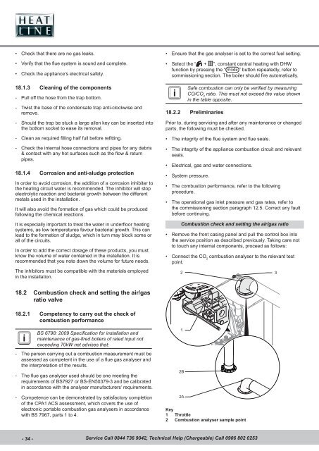
• Remove the front casing panel <strong>and</strong> pull the control box into<br />
the service position as described previously. Taking care not<br />
to touch any internal components, proceed as follows:<br />
• Connect the CO 2<br />
combustion analyser to the relevant test<br />
point.<br />
2 3<br />
18.2 Combustion check <strong>and</strong> setting the air/gas<br />
ratio valve<br />
18.2.1 Competency to carry out the check of<br />
combustion per<strong>for</strong>mance<br />
BS 6798: 2009 Specifi cation <strong>for</strong> installation <strong>and</strong><br />
maintenance of gas-fi red boilers of rated input not<br />
exceeding 70kW net advises that:<br />
- The person carrying out a combustion measurement must be<br />
assessed as competent in the <strong>use</strong> of a fl ue gas analyser <strong>and</strong><br />
the interpretation of the results.<br />
- The fl ue gas analyser <strong>use</strong>d should be one meeting the<br />
requirements of BS7927 or BS-EN50379-3 <strong>and</strong> be calibrated<br />
in accordance with the analyser manufacturers’ requirements.<br />
1<br />
2B<br />
<strong>24</strong><br />
- Competence can be demonstrated by satisfactory completion<br />
of the CPA1 ACS assessment, which covers the <strong>use</strong> of<br />
electronic portable combustion gas analysers in accordance<br />
with BS 7967, parts 1 to 4.<br />
2A<br />
Key<br />
1 Throttle<br />
2 Combustion analyser sample point<br />
- 34 - Service Call 0844 736 9042, Technical Help (Chargeable) Call 0906 802 0253