CONSOLE (CCE) SERIES - HVAC Tech Support
CONSOLE (CCE) SERIES - HVAC Tech Support
CONSOLE (CCE) SERIES - HVAC Tech Support

Create successful ePaper yourself
Turn your PDF publications into a flip-book with our unique Google optimized e-Paper software.
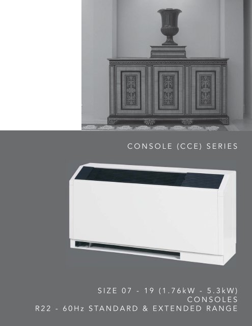
<strong>CONSOLE</strong> (<strong>CCE</strong>) <strong>SERIES</strong><br />
SIZE 07 - 19 (1.76kW - 5.3kW)<br />
<strong>CONSOLE</strong>S<br />
R22 - 60Hz STANDARD & EXTENDED RANGE
R22 - 60Hz STANDARD & EXTENDED RANGE<br />
SIZE 07 - 19 (1.76kW - 5.3kW)<br />
<strong>CONSOLE</strong>S<br />
<strong>CONSOLE</strong> (<strong>CCE</strong>) <strong>SERIES</strong>
THE SMART SOLUTION FOR ENERGY EFFICIENCY<br />
Console (<strong>CCE</strong>) Series<br />
Rev.: 05/23/07D<br />
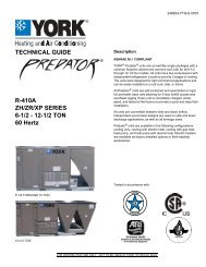
THE <strong>CONSOLE</strong> (<strong>CCE</strong>) <strong>SERIES</strong><br />
The <strong>CCE</strong> series console unit provides a high efficiency<br />
WSHP “ductless” solution for spaces where individual,<br />
quiet control of the heating and cooling system is<br />
important. <strong>CCE</strong> units are especially ideal where ceiling<br />
height and space are limited, or when preserving the<br />
integrity of an existing structure. The <strong>CCE</strong> series<br />
meets ASHRAE 90.1 efficiencies, yet maintains small<br />
cabinet dimensions.<br />
Available in sizes 1/2 ton (1.76 kW) through 1-1/2 tons<br />
(5.3 kW) with numerous cabinet, water piping and<br />
control choices, the <strong>CCE</strong> series offers a wide range<br />
of units for most any installation. The <strong>CCE</strong> has an<br />
extended range refrigerant circuit, capable of ground<br />
loop (geothermal) applications as well as water loop<br />
(boiler-tower) applications. Standard features are many.<br />
Microprocessor controls, galvanized steel cabinet,<br />
polyester powder coat paint and TXV refrigerant<br />
metering device are just some of the features of the<br />
flexible <strong>CCE</strong> series.<br />
ClimateMaster’s exclusive double isolation compressor<br />
mounting system makes the <strong>CCE</strong> series one of the<br />
quietest console units on the market. Compressors are<br />
mounted on vibration isolation springs to a heavy gauge<br />
mounting plate, which is then isolated from the cabinet<br />
base with rubber grommets for maximized vibration/<br />
sound attenuation. Options such as e-coated air coil,<br />
DDC controls, internal pump and factory-installed water<br />
solenoid valves allow customized design solutions.<br />
UNIT FEATURES<br />
• Sizes 007 (1/2 ton, 1.76 kW) through 019 (1-1/2 ton,<br />
5.3 kW)<br />
• Efficient Rotary compressors<br />
• Meets ASHRAE 90.1 efficiencies<br />
• Two-piece chassis/cabinet design<br />
• Galvanized steel cabinet with durable Polar Ice powder<br />
coat finish<br />
• Slope top/aluminum rigid bar supply air grille<br />
• Unique double isolation compressor mounting for<br />
quiet operation<br />
• TXV metering device<br />
• Extended range (20 to 120°F, -6.7 to 48.9°C) operation<br />
• ADA approved unit mounted controls, auto or manualchange-over<br />
• Remote-mounted controls available<br />
• Microprocessor controls standard (optional DXM and/or<br />
DDC controls)<br />
• LonWorks, BACnet, Modbus and Johnson N2<br />
compatibility options for DDC controls<br />
• Factory-mounted hanger brackets for horizontal units<br />
• Right or left-hand piping arrangement<br />
• Front or bottom return<br />
• Unit Performance Sentinel performance monitoring<br />
system (remote controls)<br />
• Eight Safeties Standard<br />
• Wide variety of options including e-coated air coils<br />
and internal pumps<br />
The <strong>CCE</strong> Series console water-source heat pumps<br />
are designed to meet the challenges of today’s <strong>HVAC</strong><br />
demands with a low cost/high value “ductless” solution.<br />
New EarthPure® HFC-410A<br />
console chassis available in<br />
the new Tranquility Console<br />
(TRC) Series.<br />
www.climatemaster.com<br />
<strong>CCE</strong><br />
3
CLIMATEMASTER WATER-SOURCE HEAT PUMPS<br />
Console (<strong>CCE</strong>) Series<br />
Rev.: 05/23/07D<br />
Selection Procedure<br />
Reference Calculations<br />
Heating<br />
LWT = EWT -<br />
LAT = EAT +<br />
HE<br />
GPM x 500<br />
HC<br />
CFM x1.08<br />
HR<br />
LWT = EWT +<br />
GPM x 500<br />
LAT (DB) = EAT (DB) -<br />
Cooling<br />
SC<br />
CFM x1.08<br />
LC = TC - SC<br />
S/T = SC<br />
TC<br />
Legend and Glossary of Abbreviations<br />
BTUH = BTU( British Thermal Unit) per hour<br />
CFM = airfl ow, cubic feet/minute<br />
COP = coeffi cient of performance = BTUH output/BTUH input<br />
DB = dry bulb temperature (°F)<br />
EAT = entering air temperature, Fahrenheit (dry bulb/wet bulb)<br />
EER = energy effi ciency ratio = BTUH output/Watt input<br />
EPT = external pipe thread<br />
ESP = external static pressure (inches w.g.)<br />
EWT = entering water temperature<br />
GPM = water fl ow in U.S. gallons/minute<br />
HE = total heat of extraction, BTUH<br />
HC = air heating capacity, BTUH<br />
HR = total heat of rejection, BTUH<br />
HWC = hot water generator (desuperheater) capacity, Mbtuh<br />
IPT = internal pipe thread<br />
KW = total power unit input, kilowatts<br />
LAT = leaving air temperature, °F<br />
LC = latent cooling capacity, BTUH<br />
LWT = leaving water temperature, °F<br />
MBTUH = 1000 BTU per hour<br />
S/T = sensible to total cooling ratio<br />
SC = sensible cooling capacity, BTUH<br />
TC = total cooling capacity, BTUH<br />
WB = wet bulb temperature (°F)<br />
WPD = waterside pressure drop (psi & ft. of hd.)<br />
Conversion Table - to convert inch-pound (English) to SI (Metric)<br />
Air Flow Water Flow Ext Static Pressure Water Pressure Drop<br />
Airflow (L/s) = CFM x 0.472 Water Flow (L/s) = gpm x 0.0631 ESP (Pa) = ESP (in of wg) x 249 PD (kPa) = PD (ft of hd) x 2.99<br />
<strong>CCE</strong><br />
4<br />
ClimateMaster Water-Source Heating and Cooling Systems
THE SMART SOLUTION FOR ENERGY EFFICIENCY<br />
Console (<strong>CCE</strong>) Series<br />
Rev.: 05/23/07D<br />
Selection Procedure<br />
Step 1 Determine the actual heating and cooling loads at the<br />
desired dry bulb and wet bulb conditions.<br />
Step 2 Obtain the following de sign parameters: Entering water<br />
temperature, water flow rate in GPM, air flow in CFM,<br />
water fl ow pressure drop and design wet and dry bulb<br />
temperatures. Air flow CFM should be between 300 and<br />
450 CFM per ton. Unit water pressure drop should be<br />
kept as close as possible to each other to make water<br />
balancing easier. Go to the ap pro pri ate tables and find<br />
the proper indicated water flow and water tem per a ture.<br />
Step 3 Select a unit based on total and sensible cooling<br />
conditions. Select a unit which is closest to, but no<br />
larger than, the actual cooling load.<br />
Step 4 Enter tables at the design water fl ow and water<br />
temperature. Read the total and sensible cooling<br />
capacities (Note: interpolation is per mis si ble,<br />
ex trap o la tion is not).<br />
Step 5 Read the heating capacity. If it exceeds the design<br />
criteria it is acceptable. It is quite normal for Water-<br />
Source Heat Pumps to be selected on cooling capacity<br />
only since the heating output is usually greater than the<br />
cooling capacity.<br />
Step 6 Determine the correction factors associated with the<br />
variable factors of dry bulb and wet bulb (page 14).<br />
Corrected Total Cooling =<br />
tabulated total cooling x wet bulb correction.<br />
Corrected Sensible Cooling =<br />
tabulated sensible cooling x wet/dry bulb correction.<br />
Step 7 Compare the corrected capacities to the load<br />
re quire ments. Normally if the capacities are within 10%<br />
of the loads, the equipment is ac cept able. It is better<br />
to undersize than oversize, as undersizing improves<br />
humidity control, reduces sound levels and extends the<br />
life of the equip ment.<br />
Step 8 When completed, calculate water temperature rise<br />
and assess the selection. If the units selected are not<br />
within 10% of the load cal cu la tions, then review what<br />
effect chang ing the GPM, water temperature and/or air<br />
fl ow and air tem per a ture would have on the corrected<br />
capacities. If the desired capacity cannot be achieved,<br />
select the next larger or smaller unit and repeat the<br />
procedure. Remember, when in doubt, undersize<br />
slightly for best performance.<br />
Example Equipment Selection For Cool ing<br />
Step 1 Load Determination:<br />
Assume we have determined that the appropriate cooling load<br />
at the desired dry bulb 80°F and wet bulb 65°F con di tions is<br />
as follows:<br />
Total Cooling ...................................... 11,500 BTUH<br />
Sensible Cooling ................................... 9,000 BTUH<br />
Entering Air Temp .... 80°F Dry Bulb / 65°F Wet Bulb<br />
Step 2 Design Conditions:<br />
Similarly, we have also obtained the following design pa ram e ters:<br />
Entering Water Temp ....................................... 90°F<br />
Water Flow (Based upon 12°F rise in temp.) 2.3 GPM<br />
Air Flow .................................................... 350 CFM<br />
Step 3, 4 & 5 HP Selection:<br />
After making our preliminary selection (<strong>CCE</strong>12), we enter the<br />
tables at design water fl ow and water tem per a ture and read<br />
Total Cooling, Sens. Cooling and Heat of Rej. ca pac i ties:<br />
Total Cooling ....................................... 12,000 BTUH<br />
Sensible Cooling ................................... 8,800 BTUH<br />
Heat of Rejection ................................ 15,000 BTUH<br />
Step 6 & 7 Entering Air and Airfl ow Corrections:<br />
Next, we determine our correction factors.<br />
Table Ent Air Air Flow Cor rect ed<br />
Corrected Total Cooling = 12,000 x 0.964 x 1.000 = 11,568<br />
Corrected Sens Cooling = 8,800 x 1.085 x 1.000 = 9,548<br />
Corrected Heat of Reject = 15,800 x 0.967 x 1.000 = 15,279<br />
Step 8 Water Temperature Rise Calculation & As sess ment:<br />
Actual Temperature Rise<br />
13.2°F<br />
When we compare the Corrected Total Cooling and Corrected<br />
Sensible Cooling fi gures with our load re quire ments stated<br />
in Step 1, we discover that our selection is within +/- 10%<br />
of our sensible load requirement. Fur ther more, we see that<br />
our Cor rect ed Total Cooling fi gure is slightly undersized as<br />
recommended, when compared to the actual in di cat ed load.<br />
www.climatemaster.com<br />
<strong>CCE</strong><br />
5
CLIMATEMASTER WATER-SOURCE HEAT PUMPS<br />
Console (<strong>CCE</strong>) Series<br />
Rev.: 05/23/07D<br />
<strong>CCE</strong> Series Nomenclature<br />
Model Type<br />
<strong>CCE</strong> = Console<br />
1 2 3<br />
C C E<br />
4 5 6 7 8 9 10 11 12 13 14 15<br />
0 7 B G C<br />
A<br />
S S C S R S<br />
Standard<br />
S = Standard<br />
Digital Display Controls<br />
Unit Size<br />
07<br />
09<br />
12<br />
15<br />
19<br />
Revision Level<br />
B = Current Revision<br />
Voltage<br />
A = 115/60/1<br />
E = 265/60/1<br />
G = 208-230/60/1<br />
Controls<br />
A = MCO Unit Mounted Tstat w/CXM<br />
B = MCO Unit Mounted Tstat w/DXM<br />
C = ACO Unit Mounted Tstat w/CXM<br />
D = ACO Unit Mounted Tstat w/DXM<br />
R = Remote Mounted Tstat w/CXM<br />
S = Remote Mounted Tstat w/DXM<br />
L = Remote Mounted w/CXM & LON<br />
M = Remote Mounted w/DXM & LON<br />
N = Remote Mounted w/CXM & MPC<br />
P = Remote Mounted w/DXM & MPC<br />
Power Termination<br />
A = Field Connected (Hard Wire)<br />
B = 20Amp Plug & Cord<br />
D = Disconnect Switch & 15Amp Fuse<br />
F = Disconnect Switch (Non Fused)<br />
H = 20Amp Plug, Cord, Receptacle,<br />
Disconnect Switch & 15Amp Fuse<br />
K = 20Amp Plug, Cord, Receptacle &<br />
Disconnect Switch (Non Fused)<br />
Heat Exchanger Options<br />
A = Copper Water Coil w/E-Coated Air Coil<br />
C = Copper Water Coil<br />
J = Cupro-Nickel Water Coil w/E-Coated Air Coil<br />
Subbase<br />
Cabinet Insulation<br />
Piping Connections<br />
R = Right Piping<br />
L = Left Piping<br />
Water Circuit Options Sweat IPT EPT<br />
None S F M<br />
Motorized Water Valve A G N<br />
Autoflow (2.25 Gpm/Ton) B H P<br />
Autoflow (3.0 Gpm/Ton) C J Q<br />
Motorized Water Valve & Afr (2.25) D K R<br />
Motorized Water Valve & Afr (3.0) E L T<br />
Secondary Circulation Pump U V W<br />
N = Cupro-Nickel Water Coil<br />
V = Copper Water Coil w/E-Coated Air Coil & Extended Range Insulation<br />
E = Copper Water Coil w/Extended Range Insulation<br />
M = Cupro-nickel Water Coil w/E-Coated Air Coil & Extended Range Insulation<br />
F = Cupro-nickel Water Coil w/Extended Range Insulation<br />
S = 3” Subbase<br />
D = 3” Subbase w/Motorized Damper<br />
G = 5” Subbase<br />
H = 5” Subbase w/Motorized Damper<br />
N = None<br />
S = Bottom Return<br />
M = Bottom Return w/UltraQuiet<br />
L = Bottom Return w/Locking Control Door<br />
D = Bottom Return w/Locking Control Door & UltraQuiet<br />
F = Front Return<br />
B = Front Return w/UltraQuiet<br />
G = Front Return w/Locking Control Door<br />
E = Front Return w/Locking Control Door & UltraQuiet<br />
N = No Cabinet Chassis Only<br />
C = No Cabinet Chassis Only w/UltraQuiet<br />
Rev.: 06/01/06D<br />
<strong>CCE</strong><br />
6<br />
ClimateMaster Water-Source Heating and Cooling Systems
THE SMART SOLUTION FOR ENERGY EFFICIENCY<br />
Console (<strong>CCE</strong>) Series<br />
Rev.: 05/23/07D<br />
ASHRAE/ARI/ISO 13256-1. English (IP) Units<br />
Model<br />
Performance Data<br />
ARI/ASHRAE/ISO 13256-1<br />
Water Loop Heat Pump Ground Water Heat Pump Ground Loop Heat Pump<br />
Cooling 86°F Heating 68°F Cooling 59°F Heating 50°F Cooling 77°F Heating 32°F<br />
Capacity<br />
Btuh<br />
EER<br />
Btuh/W<br />
Capacity<br />
Btuh<br />
COP<br />
Capacity<br />
Btuh<br />
EER<br />
Btuh/W<br />
Capacity<br />
Btuh<br />
COP<br />
Capacity<br />
Btuh<br />
EER<br />
Btuh/W<br />
Capacity<br />
Btuh<br />
<strong>CCE</strong>07 7,800 12.1 10,400 4.9 8,900 19.5 8,400 4.3 8,000 14.0 6,500 3.6<br />
<strong>CCE</strong>09 9,300 12.0 12,000 4.4 10,300 18.1 9,700 3.8 10,000 14.0 7,800 3.4<br />
<strong>CCE</strong>12 12,300 11.6 15,000 4.4 13,700 17.8 12,400 3.8 12,800 13.4 9,800 3.3<br />
<strong>CCE</strong>15 13,800 11.8 17,300 4.4 15,200 17.3 14,000 3.8 14,100 13.5 11,000 3.3<br />
<strong>CCE</strong>19 16,000 12.0 19,300 4.2 17,800 17.3 16,000 3.7 16,400 13.4 12,500 3.1<br />
Cooling capacities based upon 80.6°F DB, 66.2°F WB entering air temperature<br />
Heating capacities based upon 68°F DB, 59°F WB entering air temperature<br />
All air fl ow is rated on high speed<br />
All ratings based upon operation at lower voltage of dual voltage rated models<br />
COP<br />
ASHRAE/ARI/ISO 13256-1. Metric (SI) Units<br />
Model<br />
Water Loop Heat Pump Ground Water Heat Pump Ground Loop Heat Pump<br />
Cooling 30°C Heating 20°C Cooling 15°C Heating 10°C Cooling 25°C Heating 0°C<br />
Capacity<br />
Watts<br />
EER<br />
W/W<br />
Capacity<br />
Watts<br />
COP<br />
Capacity<br />
Watts<br />
EER<br />
W/W<br />
Capacity<br />
Watts<br />
COP<br />
Capacity<br />
Watts<br />
EER<br />
W/W<br />
Capacity<br />
Watts<br />
<strong>CCE</strong>07 2,286 3.5 3,048 4.9 2,608 5.7 2,462 4.3 2,345 4.1 1,905 3.6<br />
<strong>CCE</strong>09 2,726 3.5 3,517 4.4 3,019 5.3 2,843 3.8 2,931 4.1 2,286 3.4<br />
<strong>CCE</strong>12 3,605 3.4 4,396 4.4 4,015 5.2 3,634 3.8 3,751 3.9 2,872 3.3<br />
<strong>CCE</strong>15 4,045 3.5 5,070 4.4 4,455 5.1 4,103 3.8 4,132 4.0 3,224 3.3<br />
<strong>CCE</strong>19 4,689 3.5 5,657 4.2 5,217 5.1 4,689 3.7 4,807 3.9 3,664 3.1<br />
Cooling capacities based upon 27°C DB, 19°C WB entering air temperature<br />
Heating capacities based upon 20°C DB, 15°C WB entering air temperature<br />
All air fl ow is rated on high speed<br />
All ratings based upon operation at lower voltage of dual voltage rated models<br />
COP<br />
www.climatemaster.com<br />
<strong>CCE</strong><br />
7
CLIMATEMASTER WATER-SOURCE HEAT PUMPS<br />
Console (<strong>CCE</strong>) Series<br />
Rev.: 05/23/07D<br />
Performance Data<br />
Selection Notes<br />
For operation in the shaded area when water is used<br />
in lieu of an anti-freeze solution, the LWT (Leaving<br />
Water Temperature) must be calculated. Flow must be<br />
maintained to a level such that the LWT is maintained<br />
above 42°F [5.6°C] when the JW3 jumper is not clipped<br />
(see example below). This is due to the potential of the<br />
refrigerant temperature being as low as 32°F [0°C] with<br />
40°F [4.4°C] LWT, which may lead to a nuisance cutout<br />
due to the activation of the Low Temperature Protection.<br />
JW3 should never be clipped for standard range<br />
equipment or systems without antifreeze.<br />
Example:<br />
At 50°F EWT (Entering Water Temperature) and 1.5 gpm/<br />
ton, a 3 ton unit has a HE of 22,500 Btuh. To calculate<br />
LWT, rearrange the formula for HE as follows:<br />
HE = TD x GPM x 500, where HE = Heat of Extraction<br />
(Btuh); TD = temperature difference (EWT - LWT) and<br />
GPM = U.S. Gallons per Minute.<br />
TD = HE / (GPM x 500)<br />
7°F Heating - EAT 70°F<br />
HR EER HC kW HE LAT COP<br />
ended 5.5 0.50 3.8 91.0 3.22<br />
10.9 26.7 6.0 0.51 4.3 93.1 3.44<br />
10.9 29.9 6.3 0.52 4.5 94.1 3.55<br />
10.9 31.7 6.4 0.52 4.7 94.8 3.62<br />
10.8 22.9 6.9 0.53 5.1 96.5 3.79<br />
10.9 25.8 7.2 0.54 5.4 97.9 3.91<br />
10.9 27.4 7.4 0.55 5.6 98.6 3.97<br />
10.6 19.6 7.8 0.56 5.9 100.0 4.10<br />
10.8 22.1 8.2 0.57 6.3 101.6 4.23<br />
10.8 23.4 8.4 0.57 6.5 102.4 4.30<br />
10.4 16.6 8.7 0.58 6.7 103.6 4.39<br />
10 5 18 8 9 2 0 59 7 2 105 4 4 53<br />
TD = 22,500 / (4.5 x 500)<br />
TD = 10°F<br />
LWT = EWT - TD<br />
LWT = 50 - 10 = 40°F<br />
In this example, a higher fl ow rate will be required for EWTs at or below 50°F without antifreeze. At 2 gpm/ton, the<br />
calculation above results in a TD of 7.5. LWT = 50 - 7.5 = 42.5°F, which is above 42°F EWT, and is acceptable for<br />
this application.<br />
<strong>CCE</strong><br />
8<br />
ClimateMaster Water-Source Heating and Cooling Systems
THE SMART SOLUTION FOR ENERGY EFFICIENCY<br />
Console (<strong>CCE</strong>) Series<br />
Rev.: 05/23/07D<br />
Performance Data<br />
<strong>CCE</strong>07B<br />
*WPD Adder for<br />
Motorized Valve,<br />
<strong>CCE</strong>07<br />
(Cv = 4.9,<br />
MOPD = 125 psi)<br />
GPM<br />
WPD Adder<br />
PSI<br />
FT<br />
1.0 0.20 0.47<br />
1.4 0.44 1.00<br />
1.9 0.87 2.00<br />
240 CFM Nominal (Rated) Airfl ow<br />
EWT<br />
°F<br />
GPM<br />
WPD* Cooling - EAT 80/67°F Heating - EAT 70°F<br />
PSI FT TC SC Sens/Tot<br />
Ratio<br />
kW HR EER HC kW HE LAT COP<br />
20 1.9 3.7 8.5 Operation Not Recommended 5.5 0.50 3.8 91.0 3.22<br />
30<br />
40<br />
Performance capacities shown in thousands of Btuh<br />
1.0 1.4 3.2 9.7 6.9 0.71 0.36 10.9 26.7 6.0 0.51 4.3 93.1 3.44<br />
1.4 2.2 5.1 9.8 6.9 0.70 0.33 10.9 29.9 6.3 0.52 4.5 94.1 3.55<br />
1.9 3.3 7.6 9.9 6.9 0.70 0.31 10.9 31.7 6.4 0.52 4.7 94.8 3.62<br />
1.0 1.0 2.3 9.4 6.8 0.72 0.41 10.8 22.9 6.9 0.53 5.1 96.5 3.79<br />
1.4 1.5 3.5 9.6 6.9 0.71 0.37 10.9 25.8 7.2 0.54 5.4 97.9 3.91<br />
1.9 2.1 4.9 9.7 6.9 0.71 0.36 10.9 27.4 7.4 0.55 5.6 98.6 3.97<br />
1.0 0.9 2.1 9.0 6.7 0.74 0.46 10.6 19.6 7.8 0.56 5.9 100.0 4.10<br />
50<br />
1.4 1.4 3.2 9.3 6.8 0.73 0.42 10.8 22.1 8.2 0.57 6.3 101.6 4.23<br />
1.9 2.0 4.6 9.5 6.8 0.72 0.40 10.8 23.4 8.4 0.57 6.5 102.4 4.30<br />
1.0 0.8 1.8 8.6 6.5 0.76 0.52 10.4 16.6 8.7 0.58 6.7 103.6 4.39<br />
60<br />
1.4 1.3 3.0 8.9 6.6 0.74 0.48 10.5 18.8 9.2 0.59 7.2 105.4 4.53<br />
1.9 1.9 4.4 9.1 6.7 0.74 0.46 10.6 20.0 9.4 0.60 7.4 106.3 4.61<br />
1.0 0.7 1.6 8.1 6.3 0.78 0.58 10.1 14.0 9.6 0.61 7.6 107.1 4.67<br />
70<br />
1.4 1.2 2.8 8.5 6.5 0.76 0.53 10.3 15.9 10.2 0.62 8.1 109.1 4.82<br />
1.9 1.8 4.2 8.6 6.5 0.76 0.51 10.4 16.9 10.5 0.63 8.3 110.2 4.90<br />
1.0 0.7 1.6 7.6 6.1 0.79 0.65 9.8 11.8 10.6 0.63 8.4 110.7 4.93<br />
80<br />
1.4 1.1 2.5 8.0 6.2 0.78 0.60 10.0 13.3 11.1 0.64 9.0 112.9 5.10<br />
1.9 1.6 3.7 8.1 6.3 0.78 0.57 10.1 14.2 11.5 0.65 9.3 114.1 5.19<br />
1.0 0.6 1.4 7.4 5.9 0.80 0.68 9.7 10.8 11.0 0.64 8.9 112.5 5.06<br />
85<br />
1.4 1.0 2.3 7.7 6.1 0.79 0.63 9.9 12.2 11.6 0.65 9.4 114.8 5.24<br />
1.9 1.5 3.5 7.9 6.2 0.78 0.61 10.0 13.0 12.0 0.66 9.7 116.1 5.33<br />
1.0 0.6 1.4 7.2 5.8 0.81 0.72 9.6 9.9 11.5 0.65 9.3 114.2 5.19<br />
90<br />
1.4 1.0 2.3 7.5 6.0 0.80 0.67 9.8 11.1 12.1 0.66 9.9 116.7 5.38<br />
1.9 1.4 3.2 7.6 6.1 0.79 0.64 9.8 11.9 12.5 0.67 10.2 118.0 5.48<br />
1.0 0.5 1.2 6.7 5.5 0.81 0.81 9.5 8.3<br />
100<br />
1.4 0.9 2.1 7.0 5.7 0.81 0.75 9.6 9.3<br />
1.9 1.3 3.0 7.2 5.8 0.81 0.72 9.6 9.9<br />
1.0 0.5 1.2 6.4 5.2 0.81 0.91 9.5 7.0<br />
Operation Not Recommended<br />
110<br />
1.4 0.9 2.1 6.6 5.4 0.81 0.84 9.5 7.8<br />
1.9 1.3 3.0 6.7 5.5 0.81 0.81 9.5 8.3<br />
Interpolation is permissible; extrapolation is not.<br />
All entering air conditions are 80°F DB and 67°F WB in cooling, and 70°F DB in heating.<br />
ARI/ISO certifi ed conditions are 80.6°F DB and 66.2°F WB in cooling and 68°F DB in heating.<br />
Table does not refl ect fan or pump power corrections for ARI/ISO conditions.<br />
All performance is based upon the lower voltage of dual voltage rated units.<br />
Performance stated is at the rated power supply; performance may vary as the power supply varies from the rated.<br />
Operation below 40°F EWT is based upon a 15% antifreeze solution.<br />
Operation below 60°F EWT requires optional insulated water/refrigerant circuit.<br />
See performance correction tables for operating conditions other than those listed above.<br />
See Performance Data Selection Notes for operation in shaded areas.<br />
www.climatemaster.com<br />
<strong>CCE</strong><br />
9
CLIMATEMASTER WATER-SOURCE HEAT PUMPS<br />
Console (<strong>CCE</strong>) Series<br />
Rev.: 05/23/07D<br />
Performance Data<br />
<strong>CCE</strong>09B<br />
*WPD Adder for<br />
Motorized Valve,<br />
<strong>CCE</strong>09<br />
(Cv = 4.9,<br />
MOPD = 125 psi)<br />
GPM<br />
WPD Adder<br />
PSI<br />
FT<br />
1.3 0.34 0.80<br />
1.9 0.80 1.85<br />
2.5 1.50 3.46<br />
300 CFM Nominal (Rated) Airfl ow<br />
EWT<br />
°F<br />
GPM<br />
WPD* Cooling - EAT 80/67°F Heating - EAT 70°F<br />
PSI FT TC SC Sens/Tot<br />
Ratio<br />
kW HR EER HC kW HE LAT COP<br />
20 2.5 6.2 14.3 Operation Not Recommended 7.2 0.63 5.1 92.3 3.35<br />
30<br />
40<br />
Performance capacities shown in thousands of Btuh<br />
1.3 1.8 4.2 11.3 7.6 0.67 0.48 13.0 23.8 7.5 0.66 5.2 93.0 3.34<br />
1.9 3.2 7.4 11.7 7.7 0.66 0.44 13.2 26.5 7.6 0.67 5.4 93.5 3.36<br />
2.5 5.0 11.6 11.9 7.8 0.66 0.42 13.3 28.1 7.7 0.67 5.4 93.8 3.38<br />
1.3 1.5 3.5 10.9 7.4 0.68 0.54 12.8 20.4 8.1 0.69 5.8 95.1 3.46<br />
1.9 2.6 6.0 11.2 7.5 0.67 0.49 12.9 22.6 8.4 0.70 6.0 95.9 3.52<br />
2.5 4.0 9.2 11.3 7.6 0.67 0.47 13.0 23.9 8.6 0.71 6.2 96.4 3.56<br />
1.3 1.3 3.0 10.6 7.2 0.68 0.60 12.6 17.6 9.1 0.72 6.6 97.9 3.67<br />
50<br />
1.9 2.5 5.8 10.8 7.3 0.68 0.56 12.7 19.4 9.4 0.73 6.9 99.1 3.77<br />
2.5 3.9 9.0 10.9 7.4 0.67 0.53 12.8 20.5 9.7 0.74 7.1 99.7 3.82<br />
1.3 1.2 2.8 10.2 7.1 0.69 0.67 12.5 15.2 10.1 0.75 7.6 101.2 3.94<br />
60<br />
1.9 2.4 5.5 10.4 7.2 0.69 0.62 12.6 16.8 10.6 0.77 8.0 102.7 4.05<br />
2.5 3.7 8.5 10.6 7.2 0.68 0.60 12.6 17.6 10.9 0.77 8.2 103.5 4.12<br />
1.3 1.2 2.8 9.8 6.9 0.71 0.75 12.4 13.1 11.3 0.79 8.6 104.8 4.21<br />
70<br />
1.9 2.2 5.1 10.1 7.0 0.70 0.70 12.5 14.4 11.9 0.80 9.1 106.6 4.34<br />
2.5 3.5 8.1 10.2 7.1 0.69 0.67 12.5 15.2 12.2 0.81 9.4 107.5 4.42<br />
1.3 1.1 2.5 9.3 6.8 0.73 0.83 12.1 11.2 12.5 0.82 9.7 108.4 4.48<br />
80<br />
1.9 2.1 4.9 9.6 6.9 0.71 0.78 12.3 12.4 13.1 0.83 10.3 110.4 4.61<br />
2.5 3.2 7.5 9.8 6.9 0.71 0.75 12.4 13.1 13.5 0.84 10.6 111.5 4.68<br />
1.3 1.1 2.5 9.0 6.7 0.74 0.87 12.0 10.3 13.1 0.83 10.2 110.3 4.60<br />
85<br />
1.9 2.0 4.6 9.4 6.8 0.72 0.82 12.2 11.5 13.7 0.85 10.8 112.3 4.73<br />
2.5 3.1 7.2 9.6 6.9 0.72 0.79 12.3 12.1 14.1 0.86 11.2 113.4 4.79<br />
1.3 1.0 2.3 8.7 6.5 0.75 0.92 11.8 9.4 13.7 0.85 10.8 112.1 4.71<br />
90<br />
1.9 2.0 4.6 9.1 6.7 0.74 0.86 12.0 10.5 14.3 0.87 11.4 114.1 4.83<br />
2.5 3.0 6.9 9.3 6.8 0.73 0.83 12.1 11.1 14.7 0.88 11.7 115.2 4.89<br />
1.3 1.0 2.3 7.9 6.2 0.79 1.01 11.3 7.8<br />
100<br />
1.9 1.9 4.4 8.4 6.4 0.77 0.95 11.6 8.8<br />
2.5 3.0 6.9 8.6 6.5 0.76 0.92 11.8 9.4<br />
1.3 1.0 2.3 6.9 5.7 0.83 1.10 10.7 6.3<br />
Operation Not Recommended<br />
110<br />
1.9 1.9 4.4 7.5 6.0 0.80 1.04 11.1 7.2<br />
2.5 3.0 6.9 7.8 6.2 0.79 1.02 11.3 7.7<br />
Interpolation is permissible; extrapolation is not.<br />
All entering air conditions are 80°F DB and 67°F WB in cooling, and 70°F DB in heating.<br />
ARI/ISO certifi ed conditions are 80.6°F DB and 66.2°F WB in cooling and 68°F DB in heating.<br />
Table does not refl ect fan or pump power corrections for ARI/ISO conditions.<br />
All performance is based upon the lower voltage of dual voltage rated units.<br />
Performance stated is at the rated power supply; performance may vary as the power supply varies from the rated.<br />
Operation below 40°F EWT is based upon a 15% antifreeze solution.<br />
Operation below 60°F EWT requires optional insulated water/refrigerant circuit.<br />
See performance correction tables for operating conditions other than those listed above.<br />
See Performance Data Selection Notes for operation in shaded areas.<br />
<strong>CCE</strong><br />
10<br />
ClimateMaster Water-Source Heating and Cooling Systems
THE SMART SOLUTION FOR ENERGY EFFICIENCY<br />
Console (<strong>CCE</strong>) Series<br />
Rev.: 05/23/07D<br />
Performance Data<br />
<strong>CCE</strong>12B<br />
*WPD Adder for<br />
Motorized Valve,<br />
<strong>CCE</strong>12<br />
(Cv = 4.9,<br />
MOPD = 125 psi)<br />
GPM<br />
WPD Adder<br />
PSI<br />
FT<br />
1.6 0.52 1.21<br />
2.3 1.17 2.71<br />
3.1 2.31 5.33<br />
350 CFM Nominal (Rated) Airfl ow<br />
EWT<br />
°F<br />
GPM<br />
WPD* Cooling - EAT 80/67°F Heating - EAT 70°F<br />
PSI FT TC SC Sens/Tot<br />
Ratio<br />
kW HR EER HC kW HE LAT COP<br />
20 3.1 9.1 21.0 Operation Not Recommended 8.7 0.78 6.0 93.0 3.26<br />
30<br />
40<br />
Performance capacities shown in thousands of Btuh<br />
1.6 2.5 5.8 14.8 9.8 0.66 0.60 16.8 24.6 9.4 0.81 6.6 94.8 3.39<br />
2.3 4.4 10.2 14.9 9.9 0.66 0.55 16.8 27.1 9.7 0.83 6.9 95.7 3.46<br />
3.1 7.2 16.6 15.0 9.9 0.66 0.53 16.8 28.4 9.9 0.83 7.1 96.2 3.49<br />
1.6 2.0 4.6 14.4 9.6 0.67 0.68 16.7 21.3 10.6 0.86 7.7 97.9 3.63<br />
2.3 3.5 8.1 14.7 9.7 0.66 0.62 16.8 23.7 11.0 0.87 8.0 99.1 3.71<br />
3.1 5.7 13.2 14.8 9.8 0.66 0.59 16.8 24.9 11.2 0.88 8.3 99.7 3.76<br />
1.6 1.9 4.4 14.0 9.5 0.68 0.76 16.6 18.3 11.8 0.89 8.8 101.2 3.88<br />
50<br />
2.3 3.4 7.9 14.3 9.6 0.67 0.70 16.7 20.4 12.3 0.91 9.2 102.5 3.98<br />
3.1 5.5 12.7 14.5 9.6 0.67 0.67 16.7 21.6 12.6 0.92 9.5 103.2 4.03<br />
1.6 1.8 4.2 13.5 9.3 0.69 0.86 16.4 15.6 13.1 0.93 9.9 104.5 4.13<br />
60<br />
2.3 3.4 7.9 13.8 9.4 0.68 0.79 16.5 17.5 13.6 0.94 10.4 106.0 4.24<br />
3.1 5.3 12.2 14.0 9.5 0.68 0.76 16.6 18.5 13.9 0.95 10.7 106.8 4.30<br />
1.6 1.7 3.9 12.9 9.1 0.71 0.97 16.2 13.2 14.3 0.96 11.0 107.8 4.38<br />
70<br />
2.3 3.0 6.9 13.3 9.2 0.69 0.90 16.3 14.8 14.9 0.97 11.6 109.3 4.50<br />
3.1 4.6 10.6 13.5 9.3 0.69 0.86 16.4 15.7 15.2 0.98 11.9 110.1 4.56<br />
1.6 1.6 3.7 12.2 8.9 0.73 1.10 15.9 11.1 15.5 0.98 12.1 110.8 4.62<br />
80<br />
2.3 2.8 6.5 12.7 9.0 0.71 1.01 16.1 12.5 16.0 0.99 12.7 112.4 4.74<br />
3.1 4.4 10.2 12.9 9.1 0.71 0.97 16.2 13.3 16.3 1.00 12.9 113.1 4.80<br />
1.6 1.5 3.5 11.8 8.8 0.74 1.16 15.8 10.2 16.0 0.99 12.6 112.2 4.73<br />
85<br />
2.3 2.7 6.2 12.3 8.9 0.72 1.07 16.0 11.5 16.6 1.00 13.2 113.7 4.85<br />
3.1 4.4 10.2 12.6 9.0 0.72 1.03 16.1 12.2 16.9 1.01 13.4 114.5 4.91<br />
1.6 1.4 3.2 11.5 8.6 0.75 1.23 15.7 9.3 16.5 1.00 13.1 113.6 4.83<br />
90<br />
2.3 2.6 6.0 12.0 8.8 0.73 1.14 15.8 10.5 17.1 1.01 13.6 115.0 4.95<br />
3.1 4.3 9.9 12.2 8.9 0.73 1.09 15.9 11.2 17.3 1.01 13.9 115.7 5.01<br />
1.6 1.4 3.2 10.7 8.4 0.78 1.37 15.4 7.8<br />
100<br />
2.3 2.6 6.0 11.2 8.6 0.76 1.27 15.6 8.8<br />
3.1 4.3 9.9 11.5 8.6 0.75 1.23 15.7 9.4<br />
1.6 1.4 3.2 9.9 8.1 0.82 1.52 15.1 6.5<br />
Operation Not Recommended<br />
110<br />
2.3 2.6 6.0 10.4 8.3 0.79 1.42 15.3 7.3<br />
3.1 4.3 9.9 10.7 8.4 0.78 1.37 15.4 7.8<br />
Interpolation is permissible; extrapolation is not.<br />
All entering air conditions are 80°F DB and 67°F WB in cooling, and 70°F DB in heating.<br />
ARI/ISO certifi ed conditions are 80.6°F DB and 66.2°F WB in cooling and 68°F DB in heating.<br />
Table does not refl ect fan or pump power corrections for ARI/ISO conditions.<br />
All performance is based upon the lower voltage of dual voltage rated units.<br />
Performance stated is at the rated power supply; performance may vary as the power supply varies from the rated.<br />
Operation below 40°F EWT is based upon a 15% antifreeze solution.<br />
Operation below 60°F EWT requires optional insulated water/refrigerant circuit.<br />
See performance correction tables for operating conditions other than those listed above.<br />
See Performance Data Selection Notes for operation in shaded areas.<br />
www.climatemaster.com<br />
<strong>CCE</strong><br />
11
CLIMATEMASTER WATER-SOURCE HEAT PUMPS<br />
Console (<strong>CCE</strong>) Series<br />
Rev.: 05/23/07D<br />
Performance Data<br />
<strong>CCE</strong>15B<br />
*WPD Adder for<br />
Motorized Valve,<br />
<strong>CCE</strong>15<br />
(Cv = 4.9,<br />
MOPD = 125 psi)<br />
GPM<br />
WPD Adder<br />
PSI<br />
FT<br />
1.8 0.66 1.53<br />
2.7 1.62 3.74<br />
3.6 3.11 7.18<br />
400 CFM Nominal (Rated) Airfl ow<br />
EWT<br />
°F<br />
GPM<br />
WPD* Cooling - EAT 80/67°F Heating - EAT 70°F<br />
PSI FT TC SC Sens/Tot<br />
Ratio<br />
kW HR EER HC kW HE LAT COP<br />
20 3.6 4.9 11.3 Operation Not Recommended 9.9 0.93 6.7 92.8 3.10<br />
30<br />
40<br />
Performance capacities shown in thousands of Btuh<br />
1.8 1.2 2.8 16.5 11.2 0.67 0.68 18.8 24.5 10.4 0.95 7.2 94.1 3.20<br />
2.7 2.6 6.0 16.6 11.1 0.67 0.62 18.7 26.6 10.7 0.96 7.4 94.8 3.26<br />
3.6 4.2 9.7 16.6 11.0 0.67 0.60 18.6 27.6 10.9 0.97 7.6 95.2 3.29<br />
1.8 1.3 3.0 16.3 11.1 0.68 0.76 18.9 21.5 11.6 0.99 8.2 96.9 3.44<br />
2.7 2.3 5.3 16.5 11.2 0.68 0.70 18.9 23.6 12.1 1.00 8.7 97.9 3.53<br />
3.6 3.6 8.3 16.5 11.2 0.67 0.67 18.8 24.6 12.3 1.01 8.9 98.5 3.57<br />
1.8 1.2 2.8 15.8 11.0 0.70 0.85 18.7 18.7 13.1 1.03 9.6 100.2 3.72<br />
50<br />
2.7 2.2 5.1 16.2 11.1 0.69 0.78 18.8 20.6 13.7 1.05 10.1 101.6 3.84<br />
3.6 3.5 8.1 16.3 11.1 0.68 0.75 18.9 21.6 14.0 1.05 10.4 102.4 3.90<br />
1.8 1.2 2.8 15.2 10.8 0.71 0.94 18.4 16.1 14.7 1.07 11.1 104.0 4.03<br />
60<br />
2.7 2.1 4.9 15.6 10.9 0.70 0.87 18.6 17.9 15.4 1.09 11.7 105.7 4.17<br />
3.6 3.4 7.9 15.8 11.0 0.69 0.84 18.7 18.8 15.8 1.09 12.1 106.6 4.24<br />
1.8 1.1 2.5 14.3 10.5 0.73 1.04 17.9 13.7 16.4 1.10 12.6 107.8 4.34<br />
70<br />
2.7 2.0 4.6 14.9 10.7 0.72 0.97 18.2 15.3 17.2 1.12 13.4 109.7 4.50<br />
3.6 3.2 7.4 15.2 10.8 0.71 0.94 18.4 16.1 17.6 1.13 13.8 110.7 4.58<br />
1.8 1.1 2.5 13.4 10.2 0.76 1.16 17.3 11.6 18.0 1.13 14.1 111.6 4.65<br />
80<br />
2.7 2.0 4.6 14.0 10.4 0.74 1.08 17.7 13.0 18.8 1.15 14.9 113.5 4.82<br />
3.6 3.1 7.2 14.3 10.5 0.73 1.05 17.9 13.7 19.3 1.15 15.3 114.5 4.91<br />
1.8 1.1 2.5 12.9 10.0 0.78 1.21 17.0 10.6 18.8 1.14 14.8 113.3 4.80<br />
85<br />
2.7 1.9 4.4 13.5 10.3 0.76 1.14 17.4 11.9 19.6 1.15 15.6 115.2 4.98<br />
3.6 3.0 6.9 13.9 10.4 0.75 1.10 17.6 12.6 20.0 1.16 16.0 116.1 5.07<br />
1.8 1.0 2.3 12.3 9.9 0.80 1.27 16.7 9.7 19.5 1.15 15.5 115.0 4.95<br />
90<br />
2.7 1.9 4.4 13.0 10.1 0.78 1.20 17.1 10.9 20.2 1.16 16.3 116.7 5.13<br />
3.6 3.0 6.9 13.4 10.2 0.76 1.16 17.3 11.5 20.6 1.16 16.6 117.6 5.22<br />
1.8 1.0 2.3 11.1 9.4 0.85 1.40 15.9 8.0<br />
100<br />
2.7 1.8 4.2 11.9 9.7 0.82 1.32 16.4 9.0<br />
3.6 2.9 6.7 12.2 9.8 0.80 1.28 16.6 9.5<br />
1.8 1.0 2.3 9.8 8.9 0.91 1.53 15.0 6.4<br />
Operation Not Recommended<br />
110<br />
2.7 1.8 4.2 10.6 9.2 0.87 1.45 15.5 7.3<br />
3.6 2.9 6.7 11.0 9.4 0.85 1.41 15.8 7.8<br />
Interpolation is permissible; extrapolation is not.<br />
All entering air conditions are 80°F DB and 67°F WB in cooling, and 70°F DB in heating.<br />
ARI/ISO certifi ed conditions are 80.6°F DB and 66.2°F WB in cooling and 68°F DB in heating.<br />
Table does not refl ect fan or pump power corrections for ARI/ISO conditions.<br />
All performance is based upon the lower voltage of dual voltage rated units.<br />
Performance stated is at the rated power supply; performance may vary as the power supply varies from the rated.<br />
Operation below 40°F EWT is based upon a 15% antifreeze solution.<br />
Operation below 60°F EWT requires optional insulated water/refrigerant circuit.<br />
See performance correction tables for operating conditions other than those listed above.<br />
See Performance Data Selection Notes for operation in shaded areas.<br />
<strong>CCE</strong><br />
12<br />
ClimateMaster Water-Source Heating and Cooling Systems
THE SMART SOLUTION FOR ENERGY EFFICIENCY<br />
Console (<strong>CCE</strong>) Series<br />
Rev.: 05/23/07D<br />
Performance Data<br />
<strong>CCE</strong>19B<br />
*WPD Adder for<br />
Motorized Valve,<br />
<strong>CCE</strong>19<br />
(Cv = 4.9,<br />
MOPD = 125 psi)<br />
GPM<br />
WPD Adder<br />
PSI<br />
FT<br />
2.4 1.17 2.71<br />
3.6 2.88 6.64<br />
4.8 5.53 12.77<br />
460 CFM Nominal (Rated) Airfl ow<br />
EWT<br />
°F<br />
GPM<br />
WPD* Cooling - EAT 80/67°F Heating - EAT 70°F<br />
PSI FT TC SC Sens/Tot<br />
Ratio<br />
kW HR EER HC kW HE LAT COP<br />
20 4.8 7.9 18.2 Operation Not Recommended 11.2 1.05 7.6 92.5 3.13<br />
30<br />
40<br />
Performance capacities shown in thousands of Btuh<br />
2.4 2.1 4.9 20.1 13.2 0.66 0.81 22.8 24.7 12.2 1.09 8.5 94.6 3.30<br />
3.6 4.2 9.7 20.5 13.4 0.66 0.76 23.1 26.9 12.6 1.10 8.9 95.3 3.36<br />
4.8 6.8 15.7 20.7 13.5 0.65 0.74 23.2 28.1 12.8 1.11 9.0 95.7 3.40<br />
2.4 2.0 4.6 19.4 12.9 0.66 0.90 22.5 21.6 13.8 1.14 9.9 97.8 3.54<br />
3.6 3.8 8.8 19.8 13.1 0.66 0.84 22.7 23.5 14.3 1.16 10.3 98.7 3.61<br />
4.8 6.2 14.3 20.0 13.2 0.66 0.82 22.8 24.6 14.5 1.17 10.6 99.2 3.64<br />
2.4 2.0 4.6 18.7 12.5 0.67 1.00 22.1 18.8 15.5 1.21 11.4 101.1 3.76<br />
50<br />
3.6 3.7 8.5 19.2 12.7 0.66 0.94 22.4 20.5 16.0 1.23 11.9 102.2 3.83<br />
4.8 6.0 13.9 19.4 12.8 0.66 0.91 22.5 21.4 16.3 1.24 12.1 102.8 3.86<br />
2.4 1.9 4.4 18.0 12.1 0.67 1.11 21.8 16.2 17.2 1.27 12.8 104.5 3.96<br />
60<br />
3.6 3.5 8.1 18.5 12.4 0.67 1.04 22.0 17.8 17.8 1.30 13.4 105.7 4.02<br />
4.8 5.8 13.4 18.7 12.5 0.67 1.01 22.1 18.6 18.1 1.31 13.6 106.4 4.06<br />
2.4 1.8 4.2 17.2 11.8 0.68 1.23 21.4 14.0 18.8 1.34 14.2 107.8 4.13<br />
70<br />
3.6 3.3 7.6 17.7 12.0 0.68 1.16 21.6 15.3 19.4 1.36 14.8 109.0 4.19<br />
4.8 5.5 12.7 17.9 12.1 0.67 1.12 21.8 16.0 19.8 1.37 15.1 109.7 4.22<br />
2.4 1.7 3.9 16.3 11.4 0.70 1.36 20.9 12.0 20.3 1.40 15.6 110.8 4.27<br />
80<br />
3.6 3.2 7.4 16.8 11.6 0.69 1.28 21.2 13.1 20.9 1.42 16.1 112.1 4.33<br />
4.8 5.2 12.0 17.1 11.7 0.69 1.24 21.3 13.8 21.3 1.43 16.4 112.7 4.35<br />
2.4 1.6 3.7 15.8 11.2 0.71 1.43 20.7 11.1 21.0 1.42 16.2 112.2 4.33<br />
85<br />
3.6 3.1 7.2 16.4 11.4 0.70 1.35 21.0 12.2 21.6 1.44 16.7 113.4 4.39<br />
4.8 5.0 11.6 16.7 11.5 0.69 1.31 21.1 12.7 21.9 1.46 16.9 114.0 4.41<br />
2.4 1.6 3.7 15.3 11.0 0.72 1.50 20.4 10.2 21.7 1.45 16.7 113.5 4.39<br />
90<br />
3.6 3.0 6.9 15.9 11.2 0.71 1.42 20.7 11.2 22.2 1.47 17.2 114.6 4.44<br />
4.8 4.9 11.3 16.2 11.3 0.70 1.38 20.9 11.7 22.5 1.48 17.4 115.2 4.46<br />
2.4 1.6 3.7 14.1 10.5 0.75 1.65 19.8 8.6<br />
100<br />
3.6 2.9 6.7 14.8 10.8 0.73 1.56 20.1 9.5<br />
4.8 4.8 11.1 15.1 10.9 0.72 1.52 20.3 9.9<br />
2.4 1.6 3.7 12.8 10.0 0.78 1.81 19.0 7.1<br />
Operation Not Recommended<br />
110<br />
3.6 2.9 6.7 13.6 10.3 0.76 1.72 19.4 7.9<br />
4.8 4.8 11.1 13.9 10.5 0.75 1.68 19.6 8.3<br />
Interpolation is permissible; extrapolation is not.<br />
All entering air conditions are 80°F DB and 67°F WB in cooling, and 70°F DB in heating.<br />
ARI/ISO certifi ed conditions are 80.6°F DB and 66.2°F WB in cooling and 68°F DB in heating.<br />
Table does not refl ect fan or pump power corrections for ARI/ISO conditions.<br />
All performance is based upon the lower voltage of dual voltage rated units.<br />
Performance stated is at the rated power supply; performance may vary as the power supply varies from the rated.<br />
Operation below 40°F EWT is based upon a 15% antifreeze solution.<br />
Operation below 60°F EWT requires optional insulated water/refrigerant circuit.<br />
See performance correction tables for operating conditions other than those listed above.<br />
See Performance Data Selection Notes for operation in shaded areas.<br />
www.climatemaster.com<br />
<strong>CCE</strong><br />
13
CLIMATEMASTER WATER-SOURCE HEAT PUMPS<br />
Console (<strong>CCE</strong>) Series<br />
Rev.: 05/23/07D<br />
Performance Data<br />
Correction Tables<br />
Air Flow Correction Table<br />
Airfl ow Cooling Heating<br />
% of<br />
Rated<br />
Total<br />
Capacity<br />
Sensible<br />
Capacity<br />
Power<br />
Heat of<br />
Rejection<br />
Heating<br />
Capacity<br />
Power<br />
Heat of<br />
Extraction<br />
75% 0.951 0.860 0.963 0.952 0.990 1.054 0.966<br />
81% 0.964 0.894 0.973 0.965 0.993 1.035 0.977<br />
88% 0.979 0.936 0.984 0.979 0.996 1.019 0.987<br />
94% 0.990 0.969 0.992 0.990 0.998 1.008 0.994<br />
100% 1.000 1.000 1.000 1.000 1.000 1.000 1.000<br />
106% 1.010 1.033 1.008 1.010 1.002 0.994 1.005<br />
113% 1.019 1.069 1.016 1.019 1.003 0.988 1.011<br />
Entering Air Correction Table<br />
Entering<br />
Air DB°F<br />
Heating<br />
Heating<br />
Capacity<br />
Power<br />
Heat of<br />
Extraction<br />
60 1.011 0.989 1.007<br />
65 1.004 0.994 1.004<br />
68 1.002 0.997 1.002<br />
70 1.000 1.000 1.000<br />
75 0.996 1.007 0.995<br />
80 0.991 1.018 0.990<br />
Entering<br />
Air WB°F<br />
Total<br />
Capacity<br />
Cooling<br />
Sensible Cooling Capacity Multiplier -<br />
Entering DB °F<br />
70 75 80 80.6 85 90 95<br />
Power<br />
Heat of<br />
Rejection<br />
60 0.893 0.889 1.087 * * * * * 0.964 0.902<br />
65 0.964 0.692 0.884 1.085 1.108 * * * 0.988 0.967<br />
66.2 0.983 0.645 0.838 1.036 1.059 1.231 * * 0.995 0.985<br />
67 1.000 0.613 0.806 1.000 1.027 1.199 * * 1.000 1.000<br />
70 1.049 * 0.683 0.879 0.902 1.077 1.274 1.415 1.016 1.046<br />
75 1.118 * * 0.676 0.698 0.866 1.068 1.266 1.037 1.106<br />
* = Sensible capacity equals total capacity<br />
ARI/ISO/ASHRAE 13256-1 uses entering air conditions of Cooling - 80.6°F DB/66.2°F WB, 1<br />
and Heating - 68°F DB/59°F WB entering air temperature<br />
<strong>CCE</strong><br />
14<br />
ClimateMaster Water-Source Heating and Cooling Systems
THE SMART SOLUTION FOR ENERGY EFFICIENCY<br />
Console (<strong>CCE</strong>) Series<br />
Rev.: 05/23/07D<br />
Antifreeze Correction Table<br />
Antifreeze<br />
%<br />
Cooling<br />
Heating<br />
WPD<br />
Corr. Fct.<br />
EWT 30°F<br />
Antifreeze Type<br />
EWT 90°F EWT 30°F<br />
Total Cap Sens Cap Power Htg Cap Power<br />
Water 0 1.000 1.000 1.000 1.000 1.000 1.000<br />
5 0.995 0.995 1.003 0.989 0.997 1.070<br />
Propylene Glycol<br />
15 0.986 0.986 1.009 0.968 0.990 1.210<br />
25 0.978 0.978 1.014 0.947 0.983 1.360<br />
5 0.997 0.997 1.002 0.989 0.997 1.070<br />
Methanol<br />
15 0.990 0.990 1.007 0.968 0.990 1.160<br />
25 0.982 0.982 1.012 0.949 0.984 1.220<br />
5 0.998 0.998 1.002 0.981 0.994 1.140<br />
Ethanol<br />
15 0.994 0.994 1.005 0.944 0.983 1.300<br />
25 0.986 0.986 1.009 0.917 0.974 1.360<br />
5 0.998 0.998 1.002 0.993 0.998 1.040<br />
Ethylene Glycol<br />
15 0.994 0.994 1.004 0.980 0.994 1.120<br />
25 0.988 0.988 1.008 0.966 0.990 1.200<br />
www.climatemaster.com<br />
<strong>CCE</strong><br />
15
CLIMATEMASTER WATER-SOURCE HEAT PUMPS<br />
Console (<strong>CCE</strong>) Series<br />
Rev.: 05/23/07D<br />
Blower Performance &<br />
Electrical Data<br />
Blower Performance<br />
Model<br />
Rated<br />
CFM<br />
Low<br />
Speed<br />
SCFM<br />
High<br />
Speed<br />
<strong>CCE</strong>07 240 190 240<br />
<strong>CCE</strong>09 300 240 300<br />
<strong>CCE</strong>12 350 300 350<br />
<strong>CCE</strong>15 400 340 400<br />
<strong>CCE</strong>19 460 400 460<br />
Fan speed is user selectable<br />
All airfl ow is rated at lowest Voltage if unit is dual Voltage rated, i.e. 208V for 208-230V units<br />
All units ARI/ISO/ASHRAE 13256-1 rated on high fan speed<br />
All units are designed and rated for zero external static pressure (non-ducted) application<br />
Electrical Data<br />
Model<br />
Voltage<br />
Code<br />
Voltage<br />
Min/Max<br />
Voltage<br />
Compressor<br />
QTY RLA LRA<br />
Fan<br />
Motor<br />
FLA<br />
Total<br />
Unit<br />
FLA<br />
Min<br />
Circuit<br />
Amps<br />
<strong>CCE</strong>07 A 115/60/1 104-126 1 7.1 46.5 0.50 7.6 9.3 15<br />
<strong>CCE</strong>07 G 208-230/60/1 197-254 1 3.7 19.0 0.33 4.0 5.0 15<br />
<strong>CCE</strong>07 E 265/60/1 239-292 1 2.8 16.0 0.35 3.1 3.8 15<br />
<strong>CCE</strong>09 A 115/60/1 104-126 1 9.0 46.5 1.30 10.3 12.5 20<br />
<strong>CCE</strong>09 G 208-230/60/1 197-254 1 4.7 23.0 0.50 5.2 6.3 15<br />
<strong>CCE</strong>09 E 265/60/1 239-292 1 3.8 16.0 0.50 4.3 5.3 15<br />
<strong>CCE</strong>12 A 115/60/1 104-126 1 10.6 63.0 1.30 11.9 14.6 25<br />
<strong>CCE</strong>12 G 208-230/60/1 197-254 1 6.1 29.0 0.50 6.6 8.1 15<br />
<strong>CCE</strong>12 E 265/60/1 239-292 1 4.8 21.6 0.50 5.3 6.5 15<br />
<strong>CCE</strong>15 G 208-230/60/1 197-254 1 7.0 33.2 1.10 8.1 9.8 15<br />
<strong>CCE</strong>15 E 265/60/1 239-292 1 5.4 29.0 1.00 6.4 7.8 15<br />
<strong>CCE</strong>19 G 208-230/60/1 197-254 1 7.7 38.0 1.10 8.8 10.7 15<br />
<strong>CCE</strong>19 E 265/60/1 239-292 1 5.8 29.0 1.00 6.8 8.2 15<br />
Max<br />
Fuse/<br />
HACR<br />
<strong>CCE</strong><br />
16<br />
ClimateMaster Water-Source Heating and Cooling Systems
THE SMART SOLUTION FOR ENERGY EFFICIENCY<br />
Console (<strong>CCE</strong>) Series<br />
Rev.: 05/23/07D<br />
Physical Data<br />
Model 07 09 12 15 19<br />
Compressor (1 Each)<br />
Rotary<br />
Factory Charge R22 (oz) [kg] 16 [0.454] 16 [0.454] 21 [0.595] 27 [0.765] 24 [0.680]<br />
PSC Fan Motor & Blower (3 Speeds)<br />
Fan Motor (hp) [W] 1/20 [27] 1/15 [50] 1/15 [50] 1/6 [124] 1/6 [124]<br />
Blower Wheel Size (dia x w) -<br />
(in) [mm]<br />
Water Connection Size<br />
5-1/4 x 6-1/4<br />
[133 x 159]<br />
5-1/4 x 6-1/4<br />
[133 x 159]<br />
5-1/4 x 6-1/4<br />
[133 x 159]<br />
5-1/4 x 6-1/4<br />
[133 x 159]<br />
5-1/4 x 6-1/4<br />
[133 x 159]<br />
O.D. Sweat (in) [mm] 5/8 [15.9] 5/8 [15.9] 5/8 [15.9] 5/8 [15.9] 5/8 [15.9]<br />
Optional IPT Fittings (in) 1/2 1/2 1/2 1/2 1/2<br />
Optional EPT Fittings (in) 1/2 1/2 1/2 1/2 1/2<br />
Condensate Connection Size<br />
I.D. Vinyl Hose (In) [mm] 5/8 [15.9] 5/8 [15.9] 5/8 [15.9] 5/8 [15.9] 5/8 [15.9]<br />
Air Coil Size<br />
Dimensions (h x w) - (in) [mm] 8 x 26 [20.3 x 66.0] 10 x 26 [25.4 x 66.0]<br />
Filter Size<br />
Bottom Return (in) [cm] 1 - 8 x 29-1/2 x 3/8 [20.3 x 74.9 x 0.95]<br />
Front Return (In) [cm] 1 - 7 x 29-1/2 x 1/8 [17.8 x 74.9 x 0.32]<br />
Cabinet Size<br />
Bottom Return (Std. 3" Base)<br />
(W x H x D) - (In) [cm]<br />
48 x 24 x 12 [121.9 x 61.0 x 30.5]<br />
Bottom Return (Std. 5" Base)<br />
(W x H x D) - (In) [cm]<br />
48 x 26 x 12 [121.9 x 66.0 x 30.5]<br />
Bottom Return (No Subbase)<br />
(W x H x D) - (In) [cm]<br />
48 x 21 x 12 [121.9 x 53.3 x 30.5]<br />
Unit Weight<br />
Weight - Operating, (lbs) [kg] 173 [78.5] 177 [80.3] 187 [84.5] 193 [87.5] 198 [89.8]<br />
Weight - Packaged, (lbs) [kg] 181 [82.1] 185 [83.9] 195 [88.5] 201 [91.2] 206 [93.4]<br />
www.climatemaster.com<br />
<strong>CCE</strong><br />
17
CLIMATEMASTER WATER-SOURCE HEAT PUMPS<br />
Console (<strong>CCE</strong>) Series<br />
Rev.: 05/23/07D<br />
Console Cabinet Dimensions<br />
Bottom Return - Left Hand Piping<br />
Left Hand Bottom Return<br />
12.6<br />
(320)<br />
1.5<br />
(38)<br />
Discharge<br />
Air<br />
3.5<br />
(88.9)<br />
30°<br />
Control Access Door<br />
Filter located inside and at<br />
top of air inlet area. Push<br />
tabs back and down to release<br />
filter for replacement.<br />
FRONT VIEW<br />
SIDE<br />
VIEW<br />
*23.9<br />
(607)<br />
1.9<br />
(48)<br />
1.75<br />
(44.5)<br />
AIR INLET AREA<br />
33.5<br />
(851)<br />
48.0<br />
(1219)<br />
Air<br />
Inlet<br />
11.5<br />
(292) *2.9<br />
(74)<br />
12.0<br />
(305)<br />
48.0<br />
(1219)<br />
10.0<br />
(254)<br />
L.H. Pipe &<br />
Electric Area<br />
0.75<br />
(19)<br />
BOTTOM VIEW<br />
1.56<br />
(40)<br />
3.5<br />
(89)<br />
4.5<br />
(114)<br />
1(25)<br />
1 (25)<br />
REAR VIEW<br />
1.63<br />
(41)<br />
REAR<br />
A<strong>CCE</strong>SS<br />
20.0<br />
(508)<br />
21.0<br />
(533)<br />
DAMPER OPENING*<br />
48.0<br />
(1219)<br />
11.75<br />
(298)<br />
0.59<br />
(15)<br />
9.9<br />
(251)<br />
*2.9<br />
(74)<br />
Notes:<br />
All Dimensions are in inches (mm)<br />
* Dimension with 3" (76.2 mm) subbase. Add 2" (50.8 mm) to dimension shown for 5"(127 mm) subbase.<br />
Optional autoflow valve, motorized water valve and disconnect box are shown.<br />
<strong>CCE</strong><br />
18<br />
ClimateMaster Water-Source Heating and Cooling Systems
THE SMART SOLUTION FOR ENERGY EFFICIENCY<br />
Console (<strong>CCE</strong>) Series<br />
Rev.: 05/23/07D<br />
Right Hand Bottom Return<br />
Console Cabinet Dimensions<br />
Bottom Return - Right Hand Piping<br />
16<br />
(406)<br />
5<br />
(127)<br />
Discharge<br />
Air<br />
3.5<br />
(88.9)<br />
30°<br />
Filter located inside and at<br />
top of air inlet area. Push<br />
tabs back and down to release<br />
filter for replacement.<br />
Control Access Door<br />
FRONT VIEW<br />
SIDE<br />
VIEW<br />
*23.9<br />
(607)<br />
1.9<br />
(48)<br />
1.75<br />
(44.5)<br />
AIR INLET AREA<br />
33.5<br />
(851)<br />
48.0<br />
(1219)<br />
Air<br />
Inlet<br />
11.5<br />
(292) 2.9*<br />
12.0<br />
(79)<br />
(305)<br />
48.0<br />
(1219)<br />
BOTTOM VIEW<br />
10.0<br />
(254)<br />
R.H. Pipe &<br />
Electric Area<br />
0.75<br />
(19)<br />
1(25)<br />
4.5<br />
(114)<br />
3.5<br />
(89)<br />
1.56<br />
(40)<br />
1 (25)<br />
REAR<br />
A<strong>CCE</strong>SS<br />
20<br />
(508)<br />
REAR VIEW<br />
21<br />
(533)<br />
1.63<br />
(41)<br />
DAMPER OPENING*<br />
48<br />
(1219)<br />
11.75<br />
(298)<br />
0.59<br />
(15)<br />
9.81<br />
(249)<br />
2.9<br />
(79)<br />
Notes:<br />
All Dimensions are in inches (mm)<br />
* Dimension with 3" (76.2mm) subbase. Add 2" (50.8mm) to dimensions shown for 5" (127mm) subbase.<br />
Optional autoflow valve, motorized water valve and disconnect box are shown.<br />
Rev.: 08/06/05D<br />
www.climatemaster.com<br />
<strong>CCE</strong><br />
19
CLIMATEMASTER WATER-SOURCE HEAT PUMPS<br />
Console (<strong>CCE</strong>) Series<br />
Rev.: 05/23/07D<br />
Console Cabinet Dimensions<br />
Front Return - Left Hand Piping<br />
Left Hand Front Return<br />
12.6<br />
(320)<br />
1.5<br />
(38.1)<br />
Discharge<br />
Air<br />
3.5<br />
(88.9)<br />
30°<br />
Control Access Door<br />
21.0<br />
(533)<br />
FRONT VIEW<br />
7.9<br />
(201)<br />
Air<br />
Inlet<br />
SIDE<br />
VIEW<br />
21.0<br />
(533)<br />
48.0<br />
(1219)<br />
43.7<br />
(1110)<br />
Filter located behind return<br />
air grille and requires removal of<br />
cabinet front for access.<br />
12.0<br />
(305)<br />
48.0<br />
(1219)<br />
12.0<br />
(305)<br />
L.H. Pipe &<br />
Electric Area<br />
BOTTOM VIEW<br />
4.5<br />
(114)<br />
1(25)<br />
1 (25)<br />
REAR VIEW<br />
REAR<br />
A<strong>CCE</strong>SS<br />
20.0<br />
(508)<br />
21.0<br />
(533)<br />
48.0<br />
(1219)<br />
Notes:<br />
All Dimensions are in inches (mm)<br />
Optional autoflow valve, motorized water valve and disconnect box are shown.<br />
Rev.: 07/14/06D<br />
<strong>CCE</strong><br />
20<br />
ClimateMaster Water-Source Heating and Cooling Systems
THE SMART SOLUTION FOR ENERGY EFFICIENCY<br />
Console (<strong>CCE</strong>) Series<br />
Rev.: 05/23/07D<br />
Right Hand Front Return<br />
Console Cabinet Dimensions<br />
Front Return - Right Hand Piping<br />
16.0<br />
(406)<br />
5.0<br />
(127)<br />
Discharge<br />
Air<br />
3.5<br />
(88.9)<br />
30°<br />
21.0<br />
(533)<br />
Control Access Door<br />
FRONT VIEW<br />
7.9<br />
(201)<br />
Air<br />
Inlet<br />
SIDE<br />
VIEW<br />
21.0<br />
(533)<br />
48.0<br />
(1219)<br />
43.7<br />
(1110)<br />
Filter located behind return<br />
air grille and requires removal of<br />
cabinet front for access.<br />
12.0<br />
(305)<br />
48.0<br />
(1219)<br />
12.0<br />
(305) BOTTOM VIEW<br />
R.H. Pipe &<br />
Electric Area<br />
1.0 (25)<br />
4.5<br />
(114)<br />
1.0 (25)<br />
20.0<br />
(508)<br />
REAR VIEW<br />
21.0<br />
(533)<br />
REAR<br />
A<strong>CCE</strong>SS<br />
48.0<br />
(1219)<br />
Notes:<br />
All Dimensions are in inches (mm).<br />
Optional autoflow valve, motorized water valve and disconnect box are shown.<br />
Rev.: 07/14/06D<br />
www.climatemaster.com<br />
<strong>CCE</strong><br />
21
CLIMATEMASTER WATER-SOURCE HEAT PUMPS<br />
Console (<strong>CCE</strong>) Series<br />
Rev.: 05/23/07D<br />
Console Chassis Dimensions<br />
20.50<br />
(521)<br />
40.98<br />
(1040)<br />
1.84<br />
(47)<br />
3.28<br />
(83)<br />
Power Supply<br />
5.36<br />
(136)<br />
3.01<br />
(76)<br />
Control Box<br />
Water Out<br />
Water In<br />
30°<br />
0.87<br />
(22)<br />
0.75<br />
(19)<br />
Blower Deck<br />
Blower Access Panel<br />
Compressor<br />
Access<br />
Panel<br />
4.46<br />
(113)<br />
0.75<br />
(19)<br />
*16.66<br />
(423)<br />
Condensate<br />
5/8" (15.9 mm)<br />
ID Vinyl Hose<br />
*1.94<br />
(49)<br />
*7.06<br />
(179)<br />
3.88<br />
(99)<br />
11.54<br />
(293)<br />
3.43<br />
(87)<br />
Right Hand Configuration<br />
7.5<br />
(191)<br />
3.56<br />
(90)<br />
0.99<br />
(25)<br />
Optional<br />
Autoflow<br />
Valve<br />
Optional<br />
Motorized<br />
Water Valve<br />
Water Connections<br />
5/8" (15.9 mm)<br />
OD Copper,<br />
1/2" IPT or<br />
1/2" EPT<br />
Optional<br />
Autoflow<br />
Valve<br />
0.87<br />
(22)<br />
3.01<br />
(76)<br />
5.36<br />
(136)<br />
Power Supply<br />
30°<br />
Water Out<br />
Water In<br />
3.50<br />
(89)<br />
1.93<br />
(49)<br />
40.98<br />
(1041)<br />
Optional<br />
Motorized<br />
Water Valve<br />
3.42<br />
(87)<br />
*16.66<br />
(423)<br />
Blower Deck<br />
Optional<br />
Disconnect Box<br />
(mounted to cabinet<br />
not chassis)<br />
Water Connections<br />
5/8" (15.9 mm)<br />
OD Copper,<br />
1/2" IPT or<br />
1/2" EPT<br />
7.5<br />
(191)<br />
3.56<br />
(90)<br />
3.22<br />
(82)<br />
11.54<br />
(293)<br />
3.88<br />
(99)<br />
*1.94<br />
(49)<br />
*7.06<br />
(179)<br />
Condensate<br />
5/8" (15.9 mm)<br />
ID Vinyl Hose<br />
4.49<br />
(114)<br />
0.75<br />
(19)<br />
Blower Access Panel<br />
Left Hand Configuration<br />
Notes:<br />
All Dimensions are in inches (mm)<br />
* For installed dimension, add to dimension shown 2.9" [74mm] with 3" subbase and 4.9" [124mm] for 5" subbase.<br />
Optional autoflow valve, motorized water valve and disconnect box are shown.<br />
Water connection in same location regardless of connection type.<br />
Optional<br />
Disconnect Box<br />
(mounted to cabinet<br />
not chassis)<br />
Control Box<br />
Compressor<br />
Access<br />
Panel<br />
0.75<br />
(19)<br />
20.44<br />
(52)<br />
<strong>CCE</strong><br />
22<br />
ClimateMaster Water-Source Heating and Cooling Systems
THE SMART SOLUTION FOR ENERGY EFFICIENCY<br />
Console (<strong>CCE</strong>) Series<br />
Rev.: 05/23/07D<br />
Piping Detail<br />
1.84<br />
(47)<br />
3.28<br />
(83)<br />
Power Supply<br />
5.36<br />
(136)<br />
3.01<br />
(76)<br />
Control Box<br />
Water Out<br />
Water In<br />
30°<br />
0.87<br />
(22)<br />
Compressor<br />
Access<br />
Panel<br />
4.46<br />
(113)<br />
0.75<br />
(19)<br />
*16.66<br />
(423)<br />
Condensate<br />
5/8" (15.9 mm)<br />
ID Vinyl Hose<br />
*1.94<br />
(49)<br />
*7.06<br />
(179)<br />
3.88<br />
(99)<br />
11.54<br />
(293)<br />
3.43<br />
(87)<br />
7.5<br />
(191)<br />
3.56<br />
(90)<br />
0.99<br />
(25)<br />
Optional<br />
Autoflow<br />
Valve<br />
Optional<br />
Motorized<br />
Water Valve<br />
Water Connections<br />
5/8" (15.9 mm)<br />
OD Copper,<br />
1/2" IPT or<br />
1/2" EPT<br />
Right Hand Configuration<br />
Optional<br />
Disconnect Box<br />
(mounted to cabinet<br />
not chassis)<br />
Optional<br />
Autoflow<br />
Valve<br />
0.87<br />
(22)<br />
5.36<br />
(136)<br />
3.01<br />
(76)<br />
Power Supply<br />
Water Out<br />
Water In<br />
30°<br />
3.50<br />
(89)<br />
1.93<br />
(49)<br />
Optional<br />
Motorized<br />
Water Valve<br />
3.42<br />
(87)<br />
*16.66<br />
(423)<br />
Blower Deck<br />
Optional<br />
Disconnect Box<br />
(mounted to cabinet<br />
not chassis)<br />
Water Connections<br />
5/8" (15.9 mm)<br />
OD Copper,<br />
1/2" IPT or<br />
1/2" EPT<br />
Left Hand Configuration<br />
Notes:<br />
All Dimensions are in inches (mm)<br />
* For installed dimension, add to dimension shown 2.9" [74mm] with 3" subbase and 4.9" [124mm] for 5" subbase.<br />
Optional autoflow valve, motorized water valve and disconnect box are shown.<br />
Water connection in same location regardless of connection type.<br />
7.5<br />
(191)<br />
3.56<br />
(90)<br />
3.22<br />
(82)<br />
11.54<br />
(293)<br />
3.88<br />
(99)<br />
*1.94<br />
(49)<br />
*7.06<br />
(179)<br />
Condensate<br />
5/8" (15.9 mm)<br />
ID Vinyl Hose<br />
4.49<br />
(114)<br />
0.75<br />
(19)<br />
Blower Access Panel<br />
www.climatemaster.com<br />
<strong>CCE</strong><br />
23
CLIMATEMASTER WATER-SOURCE HEAT PUMPS<br />
Console (<strong>CCE</strong>) Series<br />
Rev.: 05/23/07D<br />
<strong>CCE</strong> Series Wiring Diagram Matrix<br />
Only CXM and DXM diagrams, with a representative diagram of LON and MPC Options are pre sent ed in this submittal.<br />
Other diagrams can be lo cat ed online at www.climatemaster.com using the part num bers presented below.<br />
Model<br />
<strong>CCE</strong>07 -<br />
<strong>CCE</strong>19<br />
Refrigerant<br />
Wiring Diagram<br />
Part Number<br />
Electrical Control Agency<br />
R22<br />
96B0099N50<br />
MCO/ACO -<br />
R22 96B0099N03<br />
115/60/1,<br />
REM -<br />
208-230/60/1,<br />
R22 96B0099N04<br />
265/60/1<br />
LON -<br />
R22 96B0099N05 MPC -<br />
R407C<br />
96B0099N07<br />
CXM MCO CE<br />
R407C 96B0099N08 ACO CE<br />
R407C 96B0099N09 220-240/50/1<br />
REM CE<br />
R407C 96B0099N10 LON CE<br />
R407C 96B0099N11 MPC CE<br />
R22<br />
96B0100N50<br />
MCO/ACO -<br />
R22 96B0100N03<br />
115/60/1,<br />
REM -<br />
208-230/60/1,<br />
R22 96B0100N04<br />
265/60/1<br />
LON -<br />
R22 96B0100N05 MPC -<br />
R407C<br />
96B0100N07<br />
DXM MCO CE<br />
R407C 96B0100N08 ACO CE<br />
R407C 96B0100N09 220-240/50/1<br />
REM CE<br />
R407C 96B0100N10 LON CE<br />
R407C 96B0100N11 MPC CE<br />
All wiring diagrams available at www.climatemaster.com. R407C submittals will only contain CE Mark wiring diagrams<br />
<strong>CCE</strong><br />
24<br />
ClimateMaster Water-Source Heating and Cooling Systems
THE SMART SOLUTION FOR ENERGY EFFICIENCY<br />
Console (<strong>CCE</strong>) Series<br />
Rev.: 05/23/07D<br />
Typical Wiring Diagram<br />
Manual & Auto Change Over <strong>CCE</strong> Units (Rev. B)<br />
With CXM Controller<br />
www.climatemaster.com<br />
<strong>CCE</strong><br />
25
CLIMATEMASTER WATER-SOURCE HEAT PUMPS<br />
Console (<strong>CCE</strong>) Series<br />
Rev.: 05/23/07D<br />
Typical Wiring Diagram<br />
Remote Mounted Thermostat <strong>CCE</strong> Units (Rev. B)<br />
With CXM Controller<br />
<strong>CCE</strong><br />
26<br />
ClimateMaster Water-Source Heating and Cooling Systems
THE SMART SOLUTION FOR ENERGY EFFICIENCY<br />
Console (<strong>CCE</strong>) Series<br />
Rev.: 05/23/07D<br />
Typical Wiring Diagram<br />
<strong>CCE</strong> Units (Rev. B)<br />
With CXM & LON Controller<br />
www.climatemaster.com<br />
<strong>CCE</strong><br />
27
CLIMATEMASTER WATER-SOURCE HEAT PUMPS<br />
Console (<strong>CCE</strong>) Series<br />
Rev.: 05/23/07D<br />
Typical Wiring Diagram<br />
<strong>CCE</strong> Units (Rev. B)<br />
With CXM & MPC Controller<br />
<strong>CCE</strong><br />
28<br />
ClimateMaster Water-Source Heating and Cooling Systems
THE SMART SOLUTION FOR ENERGY EFFICIENCY<br />
Console (<strong>CCE</strong>) Series<br />
Rev.: 05/23/07D<br />
Typical Wiring Diagram<br />
Manual & Auto Change Over <strong>CCE</strong> Units (Rev. B)<br />
With DXM Controller<br />
www.climatemaster.com<br />
<strong>CCE</strong><br />
29
CLIMATEMASTER WATER-SOURCE HEAT PUMPS<br />
Console (<strong>CCE</strong>) Series<br />
Rev.: 05/23/07D<br />
Typical Wiring Diagram<br />
Remote Mounted Thermostat <strong>CCE</strong> Units (Rev. B)<br />
With DXM Controller<br />
<strong>CCE</strong><br />
30<br />
ClimateMaster Water-Source Heating and Cooling Systems
THE SMART SOLUTION FOR ENERGY EFFICIENCY<br />
Console (<strong>CCE</strong>) Series<br />
Rev.: 05/23/07D<br />
Typical Wiring Diagram<br />
<strong>CCE</strong> Units (Rev. B)<br />
With DXM & LON Controller<br />
www.climatemaster.com<br />
<strong>CCE</strong><br />
31
CLIMATEMASTER WATER-SOURCE HEAT PUMPS<br />
Console (<strong>CCE</strong>) Series<br />
Rev.: 05/23/07D<br />
Typical Wiring Diagram<br />
<strong>CCE</strong> Units (Rev. B)<br />
With DXM & MPC Controller<br />
<strong>CCE</strong><br />
32<br />
ClimateMaster Water-Source Heating and Cooling Systems
THE SMART SOLUTION FOR ENERGY EFFICIENCY<br />
Console (<strong>CCE</strong>) Series<br />
Rev.: 05/23/07D<br />
Console (<strong>CCE</strong>) Series 60Hz<br />
Engineering Specifications Rev.: 04/02/07<br />
General:<br />
Furnish and install ClimateMaster “Console” Water Source Heat Pumps, as indicated on the plans. Equipment shall be completely<br />
assembled, piped and internally wired. Capacities and characteristics as listed in the schedule and the specifications that follow.<br />
Console Water Source Heat Pumps:<br />
Units shall be supplied completely factory built for an entering water temperature range from 20º to 110ºF (-6.7º to 43.3ºC) as<br />
standard. Equivalent units from other manufacturers can be proposed provided approval to bid is given 10 days prior to bid<br />
closing. All equipment listed in this section must be rated and certified in accordance with American Refrigeration Institute /<br />
International Standards Organization (ARI / ISO) and Environmental Testing Laboratories for United States and Canada (ETL-US-C).<br />
The units shall have ARI / ISO and ETL-US-C labels.<br />
Basic Construction:<br />
Console Units shall have one of the following air flow and piping arrangements: Front Inlet/Right-hand Piping; Front Inlet/<br />
Left-hand piping; Bottom Inlet/Right-hand piping; or Bottom Inlet/Left-hand piping as shown on the plans. If units with<br />
these arrangements are NOT used, the contractor is responsible for any extra costs incurred by other trades. If other<br />
arrangements make servicing difficult, the contractor must provide access panels and clear routes to ease service. Architect/<br />
Engineer must approve any changes in layout.<br />
The cabinet, wall mounting hardware and subbase shall be constructed of heavy gauge galvanized steel with a baked polyester<br />
powder coat paint finish. Corrosion protection system shall meet the stringent 1000 hour salt spray test per ASTM B117. Unit<br />
corrosion protection must meet these stringent requirements or unit(s) will not be accepted. Color will be Polar Ice. Both sides<br />
of the steel shall be painted for added protection. Additionally, the wall mounting hardware shall have welded corner bracing. The<br />
easily removable cabinet enclosure allows for easy service to the chassis, piping compartment and control compartment.<br />
All interior surfaces shall be lined with 1/4 inch (6.4mm) thick, dual density, 2 lb/ft3 (32 kg/m3) acoustic flexible blanket type glass<br />
fiber insulation with a non-woven, anti-microbial treated mat face. Insulation placement shall be designed in a manner that will<br />
eliminate any exposed edges to prevent the introduction of glass fibers into the air stream.<br />
Standard insulation must meet NFPA Fire Hazard Classification requirements 25/50 per ASTM E84, UL 723, CAN/ULC S102-M88<br />
and NFPA 90A requirements; air erosion and mold growth limits of UL-181; stringent fungal resistance test per ASTM-C1071 and<br />
ASTM G21; and shall meet zero level bacteria growth per ASTM G22. Unit insulation must meet these stringent requirements<br />
or unit(s) will not be accepted.<br />
The cabinet shall have a 30º sloped top with aluminum rigid bar type discharge grille. Aluminum discharge grille shall be<br />
anodized charcoal grey in color including hinged control door. Cabinet shall have rounded edges (0.325 inch / 8.255 mm<br />
minimum radius) on all exposed corners for safety and esthetic purposes. Units not having sloped top and rounded corners<br />
(0.325 inch / 8.255 mm minimum) on front, side, top slope, and top corners shall not be accepted.<br />
Return Air Filter shall be 3/8” (9.5mm) permanent cleanable media type or 1/8” (3.2mm) for front return type units.<br />
Option: The unit shall be provided with a keyed lock on the control access door.<br />
Option: The unit shall be provided with a motorized outside air damper and damper assembly, factory mounted and wired.<br />
Option: The unit shall be provided with a 5 inch (127mm) high subbase (3 inch / 76.2mm subbase is standard).<br />
Option: The unit shall be provided without a subbase (3 inch / 76.2mm high subbase is standard).<br />
Option: The unit shall include a front return air grille integrally stamped into Cabinet (no subbase allowed).<br />
Option: The unit shall be supplied with extended range Insulation option, which adds closed cell insulation to internal water lines,<br />
and provides insulation on suction side refrigeration tubing including refrigerant to water heat exchanger.<br />
Fan and Motor Assembly:<br />
Fan and motor assembly shall be assembled on a slide out fan deck with quick electrical disconnecting means to provide and<br />
facilitate easy field servicing. The fan motor shall be multi-speed, permanently lubricated, PSC type, with internal thermal<br />
overload protection. Units supplied without permanently lubricated motors must provide external oilers for easy service. The fan<br />
motor shall include a torsionally flexible motor mounting system or saddle mount system with resilient rings to inhibit vibration<br />
www.climatemaster.com<br />
<strong>CCE</strong><br />
33
CLIMATEMASTER WATER-SOURCE HEAT PUMPS<br />
Console (<strong>CCE</strong>) Series<br />
Rev.: 05/23/07D<br />
induced high noise levels associated with “hard wire belly band” motor mounting. The airflow rating of the unit shall be based on<br />
a wet coil and a clean filter in place. Ratings based on a dry coil and / or no filter shall NOT be acceptable.<br />
Refrigerant Circuit:<br />
Units shall have a sealed refrigerant circuit including a high efficiency rotary compressor designed for heat pump operation,<br />
a thermostatic expansion valve for refrigerant metering, an enhanced corrugated aluminum lanced fin and rifled copper tube<br />
refrigerant to air heat exchanger, reversing valve, coaxial (tube in tube) refrigerant to water heat exchanger, and safety controls<br />
including a high pressure switch, low pressure switch (loss of charge), water coil low temperature sensor, and air coil low<br />
temperature sensor. Access fittings shall be factory installed on high and low pressure refrigerant lines to facilitate field service.<br />
Activation of any safety device shall prevent compressor operation via a microprocessor lockout circuit. The lockout circuit shall be<br />
reset at the thermostat or at the contractor supplied disconnect switch. Units that cannot be reset at the thermostat shall not<br />
be acceptable.<br />
Hermetic compressors shall be internally sprung. The compressor shall have a dual level vibration isolation system. The<br />
compressor will be mounted on computer selected vibration isolation grommets to a large heavy gauge compressor mounting<br />
tray plate, which is then isolated from the cabinet base with rubber grommets for maximized vibration attenuation. Compressor<br />
shall have thermal overload protection. Compressor shall be located in an insulated compartment away from air stream to<br />
minimize sound transmission.<br />
Refrigerant to air heat exchangers shall utilize enhanced corrugated lanced aluminum fins and rifled copper tube construction<br />
rated to withstand 450 PSIG (3101 kPa) refrigerant working pressure. Refrigerant to water heat exchangers shall be of copper<br />
inner water tube and steel refrigerant outer tube design, rated to withstand 450 PSIG (3101 kPa) working refrigerant pressure and<br />
450 PSIG (3101 kPa) working water pressure. The refrigerant to water heat exchanger shall be “electro-coated” with a low cure<br />
cathodic epoxy material a minimum of 0.4 mils thick (0.4 – 1.5 mils range) on all surfaces. The black colored coating shall provide<br />
a minimum of 1000 hours salt spray protection per ASTM B117-97 on all external steel and copper tubing. The material shall be<br />
formulated without the inclusion of any heavy metals and shall exhibit a pencil hardness of 2H (ASTM D3363-92A), crosshatch<br />
adhesion of 4B-5B (ASTM D3359-95), and impact resistance of 160 in-lbs (184 kg-cm) direct (ASTM D2794-93).<br />
Refrigerant metering shall be accomplished by thermostatic expansion valve only. Expansion valves shall be dual port balanced<br />
types with external equalizer for optimum refrigerant metering. Units shall be designed and tested for operating ranges of<br />
entering water temperatures from 20° to 110°F (-6.7° to 43.3°C). Reversing valve shall be four-way solenoid activated refrigerant<br />
valve, which shall default to heating mode should the solenoid fail to function. If the reversing valve solenoid defaults to cooling<br />
mode, an additional low temperature thermostat must be provided to prevent over-cooling an already cold room.<br />
Option: The unit will be supplied with cupro nickel coaxial water to refrigerant heat exchanger.<br />
Option: The unit will be supplied with internally factory mounted two-way water valve for variable speed pumping requirements.<br />
A factory-mounted or field-installed high pressure switch shall be installed in the water piping to disable compressor<br />
operation in the event water pressures build due to water freezing in the piping system.<br />
Option: The unit will be supplied with internally factory mounted automatic water flow regulators.<br />
Option: The unit will be supplied with internally mounted secondary pump for primary/secondary applications, specifically onepipe<br />
systems.<br />
Option: The unit shall be supplied with extended range Insulation option, which adds closed cell insulation to internal water lines,<br />
and provides insulation on suction side refrigeration tubing including refrigerant to water heat exchanger.<br />
Option: The refrigerant to air heat exchanger shall be “electro-coated” with a low cure cathodic epoxy material a minimum of 0.4<br />
mils thick (0.4 – 1.5 mils range) on all surfaces. The black colored coating shall provide a minimum of 1000 hours salt spray<br />
protection per ASTM B117-97 on all galvanized end plates and copper tubing, and a minimum of 2000 hours of salt spray<br />
on all aluminum fins. The material shall be formulated without the inclusion of any heavy metals and shall exhibit a pencil<br />
hardness of 2H (ASTM D3363-92A), crosshatch adhesion of 4B-5B (ASTM D3359-95), and impact resistance of 160 in-lbs<br />
(184 kg-cm) direct (ASTM D2794-93).<br />
Piping:<br />
Water piping shall terminate in the same location regardless of the connection and valve options.<br />
Option: Threaded EPT copper fittings (sweat connections are standard).<br />
Option: Threaded IPT copper fittings (sweat connections are standard).<br />
<strong>CCE</strong><br />
34<br />
ClimateMaster Water-Source Heating and Cooling Systems
THE SMART SOLUTION FOR ENERGY EFFICIENCY<br />
Console (<strong>CCE</strong>) Series<br />
Rev.: 05/23/07D<br />
Drain Pan:<br />
The drain pan shall be constructed of galvanized steel and have a powder coat paint application to further inhibit corrosion. This<br />
corrosion protection system shall meet the stringent 1000 hour salt spray test per ASTM B117. If plastic type material is used,<br />
it must be HDPE (High Density Polyethylene) to avoid thermal cycling shock stress failure over the lifetime of the unit. Stainless<br />
Steel materials are also acceptable. Drain pan shall be fully insulated. Drain outlet shall be located at pan as to allow complete<br />
and unobstructed drainage of condensate. The unit as standard will be supplied with solid-state electronic condensate overflow<br />
protection. Mechanical float switches will NOT be accepted.<br />
Electrical:<br />
Unit controls shall be located under the hinged control door in the sloped top grille. Operating controls shall consist of slide<br />
switches to select “OFF”, “HEAT,” “COOL,” “AUTO” (when equipped with auto change-over option – “AUTO” is not available<br />
for standard manual change-over controls), Fan “AUTO” (fan cycles with compressor), Fan “ON” (continuous fan), Fan “LO” (low<br />
speed fan), and Fan “HI” (high speed fan). Temperature adjustment shall be accomplished via two push buttons, one labeled with<br />
an arrow up, and the other labeled with an arrow down. Controls shall include an LCD display for display of temperature and set<br />
point. Units without an LCD display shall not be accepted.<br />
A control box shall be located above the unit compressor compartment and shall contain operating controls as outlined in the<br />
paragraph above, 24VAC transformer, double-pole compressor relay, and solid-state controller for complete unit operation.<br />
Reversing valve and fan motor wiring shall be routed through this electronic controller. Units shall be name-plated for use with time<br />
delay fuses or HACR circuit breakers. A unit-mounted digital thermostat with a remote bulb measuring return air temperature shall<br />
control the compressor operation for heating and cooling. Control shall be equipped with a fan switch (provides options to cycle fan<br />
with compressor or provide continuous fan) and a fault indicator light. Units without a fault indicator light shall not be accepted.<br />
Option: Digital ACO unit mounted thermostat (MCO is standard).<br />
Option: Provisions for remote thermostat (unit mounted is standard).<br />
Option: Disconnect Switch, Non-Fused.<br />
Option: Disconnect Switch, Fused with 15A fuse.<br />
Option: 20A power plug/cord.<br />
Option: 20A plug, cord, receptacle, disconnect switch, fused with 15A fuse.<br />
Option: 20A plug, cord, receptacle, disconnect switch, non fused.<br />
Solid State Control System (CXM):<br />
Units shall have a solid-state control system. Units utilizing electro-mechanical control shall not be acceptable. The control<br />
system microprocessor board shall be specifically designed to protect against building electrical system noise contamination,<br />
EMI, and RFI interference. The control system shall interface with a heat pump type thermostat. The control system shall have the<br />
following features:<br />
a. Anti-short cycle time delay on compressor operation.<br />
b. Random start on power up mode.<br />
c. Low voltage protection.<br />
d. High voltage protection.<br />
e. Unit shutdown on high or low refrigerant pressures.<br />
f. Unit shutdown on low water temperature.<br />
g. Condensate overflow electronic protection.<br />
h. Option to reset unit at thermostat or disconnect.<br />
i. Automatic intelligent reset. Unit shall automatically reset the unit 5 minutes after trip if the fault has cleared. If a fault occurs<br />
3 times sequentially without thermostat meeting temperature, then lockout requiring manual reset will occur.<br />
j. Ability to defeat time delays for servicing.<br />
k. Light emitting diode (LED) on circuit board to indicate high pressure, low pressure, low voltage, high voltage, low water/air<br />
temperature cut-out, condensate overflow, and control voltage status.<br />
l. The low-pressure switch shall not be monitored for the first 120 seconds after a compressor start command to prevent<br />
nuisance safety trips.<br />
m. 24V output to cycle a motorized water valve or other device with compressor contactor.<br />
n. Unit Performance Sentinel (UPS). The UPS warns when the heat pump is running inefficiently.<br />
o. Water coil low temperature sensing (selectable for water or anti-freeze).<br />
p. Air coil low temperature sensing.<br />
www.climatemaster.com<br />
<strong>CCE</strong><br />
35
CLIMATEMASTER WATER-SOURCE HEAT PUMPS<br />
Console (<strong>CCE</strong>) Series<br />
Rev.: 05/23/07D<br />
NOTE: Units not providing the 8 safety protections of anti-short cycle, low voltage, high voltage, high refrigerant pressure,<br />
low pressure (loss of charge), air coil low temperature cut-out, water coil low temperature cut-out, and condensate<br />
overflow protections will not be accepted.<br />
Option: Enhanced solid state control system (DXM)<br />
This control system features two stage control of cooling and two stage control of heating modes for exacting temperature and<br />
dehumidification purposes.<br />
This control system coupled with a multi-stage thermostat will better dehumidify room air by automatically running the heat<br />
pump’s fan at lower speed on the first stage of cooling thereby implementing low sensible heat ratio cooling. On the need for<br />
higher cooling performance the system will activate the second stage of cooling and automatically switch the fan to the higher<br />
fan speed setting. This system may be further enhanced with a humidistat. Units not having automatic low sensible heat ratio<br />
cooling will not be accepted; as an alternate a hot gas reheat coil may be provided with control system for automatic activation.<br />
Control shall have all of the above mentioned features of the CXM control system along with the following expanded features:<br />
a. Removable thermostat connector.<br />
b. Night setback control.<br />
c. Random start on return from night setback.<br />
d. Minimized reversing valve operation (Unit control logic shall only switch the reversing valve when cooling is demanded for<br />
the first time. The reversing valve shall be held in this position until the first call for heating, ensuring quiet operation and<br />
increased valve life.).<br />
e. Override temperature control with 2-hour (adjustable) timer for room occupant to override setback temperature at the<br />
thermostat.<br />
f. Dry contact night setback output for digital night setback thermostats.<br />
g. Ability to work with heat pump or heat/cool (Y, W) type thermostats.<br />
h. Ability to work with heat pump thermostats using O or B reversing valve control.<br />
i. Emergency shutdown contacts.<br />
j. Boilerless system heat control at low loop water temperature.<br />
k. Ability to allow up to 3 units to be controlled by one thermostat.<br />
l. Relay to operate an external damper.<br />
m. Ability to automatically change fan speed from multistage thermostat.<br />
n. Relay to start system pump.<br />
o. 75 VA control transformer. Control transformer shall have load side short circuit and overload protection via a built in circuit<br />
breaker.<br />
Remote Service Sentinel (CXM/DXM):<br />
Solid state control system shall communicate with thermostat to display (at the thermostat) the unit status, fault status, and<br />
specific fault condition, as well as retrieve previously stored fault that caused unit shutdown. The Remote Service Sentinel allows<br />
building maintenance personnel or service personnel to diagnose unit from the wall thermostat. The control board shall provide a<br />
signal to the thermostat fault light, indicating a lockout. Upon cycling the G (fan) input 3 times within a 60 second time period, the<br />
fault light shall display the specific code as indicated by a sequence of flashes. A detailed flashing code shall be provided at the<br />
thermostat LED to display unit status and specific fault status such as over/under voltage fault, high pressure fault, low pressure<br />
fault, low water temperature fault, condensate overflow fault, etc. Units that do not provide this remote service sentinel shall<br />
not be acceptable.<br />
Option: Lonworks interface system<br />
Units shall have all the features listed above (either CXM or DXM) and the control board will be supplied with a LONWORKS<br />
interface board, which is LONMark certified. This will permit all units to be daisy chained via a 2-wire twisted pair shielded cable.<br />
The following points must be available at a central or remote computer location:<br />
a. Space temperature<br />
b. Leaving water temperature<br />
c. Discharge air temperature<br />
d. Command of space temperature setpoint<br />
e. Cooling status<br />
f. Heating status<br />
g. Low temperature sensor alarm<br />
h. Low pressure sensor alarm<br />
i. High pressure switch alarm<br />
j. Condensate sensor alarm<br />
k. Hi/low voltage alarm<br />
<strong>CCE</strong><br />
36<br />
ClimateMaster Water-Source Heating and Cooling Systems
THE SMART SOLUTION FOR ENERGY EFFICIENCY<br />
Console (<strong>CCE</strong>) Series<br />
Rev.: 05/23/07D<br />
l. Fan “ON/AUTO” position of space thermostat as specified above<br />
m. Unoccupied / occupied command<br />
n. Cooling command<br />
o. Heating command<br />
p. Fan “ON / AUTO” command<br />
q. Fault reset command<br />
r. Itemized fault code revealing reason for specific shutdown fault (any one of 7)<br />
This option also provides the upgraded 75VA control transformer with load side short circuit and overload protection via a built in<br />
circuit breaker.<br />
Option: MPC (Multiple Protocol Control) interface system<br />
Units shall have all the features listed above (either CXM or DXM) and the control board will be supplied with a Multiple Protocol<br />
interface board. Available protocols are BACnet MS/TP, Modbus, or Johnson Controls N2. The choice of protocol shall be field<br />
selectable/changeable via the use of a simple selector switch. Protocol selection shall not require any additional programming or<br />
special external hardware or software tools. This will permit all units to be daisy chain connected by a 2-wire twisted pair shielded<br />
cable. The following points must be available at a central or remote computer location:<br />
a. Space temperature<br />
b. Leaving water temperature<br />
c. Discharge air temperature<br />
d. Command of space temperature setpoint<br />
e. Cooling status<br />
f. Heating status<br />
g. Low temperature sensor alarm<br />
h. Low pressure sensor alarm<br />
i. High pressure switch alarm<br />
j. Condensate overflow alarm<br />
k. Hi/low voltage alarm<br />
l. Fan “ON/AUTO” position of space thermostat as specified above<br />
m. Unoccupied / occupied command<br />
n. Cooling command<br />
o. Heating command<br />
p. Fan “ON / AUTO” command<br />
q. Fault reset command<br />
r. Itemized fault code revealing reason for specific shutdown fault (any one of 7)<br />
This option also provides the upgraded 75VA control transformer with load side short circuit and overload protection via a built in<br />
circuit breaker.<br />
Warranty:<br />
Climate Master shall warranty equipment for a period of 12 months from start up or 18 months from shipping (which ever occurs first).<br />
Option: Extended 4-year compressor warranty covers compressor for a total of 5 years.<br />
Option: Extended 4-year refrigeration circuit warranty covers coils, reversing valve, expansion valve and compressor for a total of<br />
5 years.<br />
Option: Extended 4-year control board warranty covers the CXM/DXM control board for a total of 5 years.<br />
FIELD INSTALLED OPTIONS<br />
Hose Kits:<br />
Hoses shall be 1 foot (31cm) long, braided stainless steel; fire rated hoses complete with adapters. Only fire rated hoses will be<br />
accepted. Note: Threaded connection piping option must be ordered for hose kit connections.<br />
Option: 2 foot (61cm) hose lengths instead of standard 1 foot (31cm) length.<br />
Valves:<br />
The following valves are available and will be shipped loose:<br />
a. Ball valve; bronze material, standard port full flow design, IPT connections.<br />
b. Ball valve with memory stop and PT Port; standard port full flow design, IPT connections.<br />
c. “Y” strainer with cap; bronze material, IPT connections.<br />
d. “Y” strainer with blowdown valve; bronze material, IPT connections.<br />
www.climatemaster.com<br />
<strong>CCE</strong><br />
37
CLIMATEMASTER WATER-SOURCE HEAT PUMPS<br />
Console (<strong>CCE</strong>) Series<br />
Rev.: 05/23/07D<br />
e. Motorized water valve; slow acting, 24v, IPT connections.<br />
Hose Kit Assemblies:<br />
The following assemblies ship with the valves already assembled to the hose described:<br />
a. Supply and return hoses having ball valve with PT port.<br />
b. Supply hose having ball valve with PT port; return hose having automatic flow regulator valve (Measureflo) with PT ports, and<br />
ball valve.<br />
c. Supply hose having “Y” strainer with blowdown valve, and ball valve with PT port; return hose having automatic flow<br />
regulator (Measureflo) with PT ports, and ball valve.<br />
Thermostats:<br />
The thermostat shall be a ClimateMaster mechanical or electronic type thermostat as selected below with the described features<br />
(Note: “Remote mounted thermostat” control option must be selected for the console unit):<br />
a. Single Stage Standard Manual Changeover (ATM11C01)<br />
Thermostat shall be a single-stage, vertical mount, manual changeover with HEAT-OFF-COOL system switch and fan ON-<br />
AUTO switch. Thermostat shall have a mechanical temperature indicator and set point indication. Thermostat shall only<br />
require 4 wires for connection. Mercury bulb thermostats are not acceptable.<br />
b. Single Stage Digital Manual Changeover with Two-Speed Fan Control (ATM11C03) – Recommended for Console Remote-<br />
Mount Thermostat (DXM required)<br />
Thermostat shall be a single-stage, digital, manual changeover with HEAT-OFF-COOL system switch, fan ON-AUTO switch,<br />
and fan LO-HI switch. Thermostat shall have an LCD display with temperature and set-point(s) in ºF or ºC. The Thermostat<br />
shall provide permanent memory of set-point(s) without batteries. A fault LED shall be provided to display specific fault<br />
condition. Thermostat shall come standard with remote temperature sensor, but may be operated with internal sensor if<br />
desired via installation of a jumper.<br />
c. Single Stage Digital Auto or Manual Changeover (ATA11U01)<br />
Thermostat shall be a single-stage, digital, auto or manual changeover with HEAT-OFF-COOL-AUTO system switch and fan<br />
ON-AUTO switch. Thermostat shall have an LCD display with temperature and set-point(s) in ºF or ºC. The Thermostat shall<br />
provide permanent memory of set-point(s) without batteries. A fault LED shall be provided to display specific fault condition.<br />
Thermostat shall provide temperature display offset for custom applications.<br />
d. Single Stage Digital Automatic Changeover with Two-Speed Fan Control (ATA11C04) – Recommended for Console Remote-<br />
Mount Thermostat (DXM required)<br />
Thermostat shall be a single-stage, digital, auto or manual changeover with HEAT-OFF-COOL-AUTO system switch, fan<br />
ON-AUTO switch, and fan LO-HI switch. Thermostat shall have an LCD display with temperature and set-point(s) in ºF or ºC.<br />
The Thermostat shall provide permanent memory of set-point(s) without batteries. A fault LED shall be provided to display<br />
specific fault condition. Thermostat shall come standard with remote temperature sensor, but may be operated with internal<br />
sensor if desired via installation of a jumper.<br />
e. Multistage Digital Automatic Changeover (ATA22U01)<br />
Thermostat shall be multi-stage (2H/2C), manual or automatic changeover with HEAT-OFF-COOL-AUTO system settings and<br />
fan ON-AUTO settings. Thermostat shall have an LCD display with temperature, set-point(s), mode, and status indication.<br />
The temperature indication shall be selectable for ºF or ºC. The thermostat shall provide permanent memory of set-point(s)<br />
without batteries. A fault LED shall be provided to indicate specific fault condition(s). Thermostat shall provide temperature<br />
display offset for custom applications. Thermostat shall allow unit to provide better dehumidification with optional DXM<br />
controller by automatically using lower fan speed on stage 1 cooling (higher latent cooling) as main cooling mode, and<br />
automatically shifting to high speed fan on stage 2 cooling.<br />
f. Single Stage Manual Changeover Programmable 5/2 Day (ATP11N01)<br />
Thermostat shall be 5 day/2 day programmable (with up to 4 set points per day), single stage (1H/1C), manual changeover<br />
with HEAT-OFF-COOL system settings and fan ON-AUTO settings. Thermostat shall have an LCD display with temperature,<br />
set-point(s), mode, and status indication. The temperature indication shall be selectable for ºF or ºC. The thermostat shall<br />
provide permanent memory of set-point(s) without batteries. Thermostat shall provide convenient override feature to<br />
temporarily change set point.<br />
g. Multistage Automatic or Manual Changeover Programmable 5/2 Day (ATP21U01)<br />
Thermostat shall be 5 day/2 day programmable (with up to 4 set points per day), multi-stage (2H/1C), automatic or manual<br />
changeover with HEAT-OFF-COOL-AUTO system settings and fan ON-AUTO settings. Thermostat shall have an LCD display<br />
with temperature, set-point(s), mode, and status indication. The temperature indication shall be selectable for ºF or ºC. The<br />
thermostat shall provide permanent memory of set-point(s) without batteries. Thermostat shall provide convenient override<br />
feature to temporarily change set point.<br />
h. Multistage Automatic or Manual Changeover Programmable 7 Day (ATP32U01)<br />
Thermostat shall be 7 day programmable (with up to 4 set points per day), multi-stage (3H/2C), automatic or manual<br />
changeover with HEAT-OFF-COOL-AUTO system settings and fan ON-AUTO settings. Thermostat shall have a blue backlit<br />
dot matrix LCD display with temperature, set-points, mode, and status indication. The temperature indication shall be<br />
<strong>CCE</strong><br />
38<br />
ClimateMaster Water-Source Heating and Cooling Systems
THE SMART SOLUTION FOR ENERGY EFFICIENCY<br />
Console (<strong>CCE</strong>) Series<br />
Rev.: 05/23/07D<br />
selectable for ºF or ºC. Time display shall be selectable for 12 or 24 hour clock. Fault identification shall be provided (when<br />
used with ClimateMaster CXM or DXM controls) to simplify troubleshooting by providing specific unit fault at the thermostat<br />
with red backlit LCD during unit lockout. The thermostat shall provide permanent memory of set-points without batteries.<br />
Thermostat shall provide heating set-point range limit, cooling set-point range limit, temperature display offset, keypad<br />
lockout, dead-band range setting, and inter-stage differential settings. Thermostat shall provide progressive recovery to<br />
anticipate time required to bring space temperature to the next programmed event. Thermostat shall provide an installer<br />
setup for configuring options and for setup of servicing contractor name and contact information. Thermostat shall allow the<br />
use of an accessory remote and/or outdoor temperature sensor (AST008). Thermostat navigation shall be accomplished via<br />
five buttons (up/down/right/left/select) with menu-driven selections for ease of use and programming.<br />
i. Multistage Automatic or Manual Changeover Programmable 7 Day with Humidity Control (ATP32U02)<br />
Thermostat shall be 7 day programmable (with up to 4 set points per day), multi-stage (3H/2C), automatic or manual<br />
changeover with HEAT-OFF-COOL-AUTO system settings and fan ON-AUTO settings. Separate dehumidification and<br />
humidification set points shall be configurable for discreet outputs to a dehumidification option and/or an external<br />
humidifier. Installer configuration mode shall allow thermostat dehumidification mode to operate with ClimaDry reheat or<br />
with ECM fan dehumidification mode via settings changes. Thermostat shall have a blue backlit dot matrix LCD display<br />
with temperature, relative humidity, set-points, mode, and status indication. The temperature indication shall be selectable<br />
for ºF or ºC. Time display shall be selectable for 12 or 24 hour clock. Fault identification shall be provided (when used with<br />
ClimateMaster CXM or DXM controls) to simplify troubleshooting by providing specific unit fault at the thermostat with red<br />
backlit LCD during unit lockout. The thermostat shall provide permanent memory of set-points without batteries. Thermostat<br />
shall provide heating set-point range limit, cooling set-point range limit, temperature display offset, keypad lockout,<br />
dead-band range setting, and inter-stage differential settings. Thermostat shall provide progressive recovery to anticipate<br />
time required to bring space temperature to the next programmed event. Thermostat shall provide an installer setup for<br />
configuring options and for setup of servicing contractor name and contact information. Thermostat shall allow the use of<br />
an accessory remote and/or outdoor temperature sensor (AST008). Thermostat navigation shall be accomplished via five<br />
buttons (up/down/right/left/select) with menu-driven selections for ease of use and programming.<br />
DDC Sensors:<br />
ClimateMaster wall mounted DDC sensor to monitor room temperature and interfaces with optional interface system described<br />
above. Several types as described below:<br />
a. Sensor only with no display (LON and MPC).<br />
b. Sensor with override (LON only).<br />
c. Sensor with setpoint and adjustment override (MPC only).<br />
d. Sensor with setpoint and adjustment override, LCD display, status/fault indication (LON and MPC).<br />
www.climatemaster.com<br />
<strong>CCE</strong><br />
39
CLIMATEMASTER WATER-SOURCE HEAT PUMPS<br />
Console (<strong>CCE</strong>) Series<br />
Rev.: 05/23/07D<br />
Section Change Log<br />
Date: Item: Action:<br />
05/23/07 Specifi cations Updated for new Safety Agency<br />
01/01/07 Motorized Valves Updates Valve Cv & MOPD values<br />
01/01/07 Motorized Valves Updated wiring diagrams to show H.P. switch<br />
01/01/07 Motorized Valves Updated Specs to show H.P. switch<br />
01/01/07 Controls Added information on digital unit mounted control<br />
(Rev. B)<br />
01/01/07 Controls Updated Specs with information on digital unit<br />
mounted control (Rev. B)<br />
01/01/07 Controls Updated decoder to Rev. B<br />
01/01/07 Motorized Valves Adjusted Cv values<br />
01/01/06 First Published<br />
<strong>CCE</strong><br />
40<br />
ClimateMaster Water-Source Heating and Cooling Systems
THE SMART SOLUTION FOR ENERGY EFFICIENCY<br />
Console (<strong>CCE</strong>) Series<br />
Rev.: 05/23/07D<br />
Notes:<br />
www.climatemaster.com<br />
<strong>CCE</strong><br />
41
CLIMATEMASTER WATER-SOURCE HEAT PUMPS<br />
Console (<strong>CCE</strong>) Series<br />
Rev.: 05/23/07D<br />
<strong>CCE</strong><br />
42<br />
ClimateMaster Water-Source Heating and Cooling Systems