

Introduction to the Agilent 7100 Capillary Electrophoresis System
Introduction to the Agilent 7100 Capillary Electrophoresis System
Introduction to the Agilent 7100 Capillary Electrophoresis System

Create successful ePaper yourself
Turn your PDF publications into a flip-book with our unique Google optimized e-Paper software.
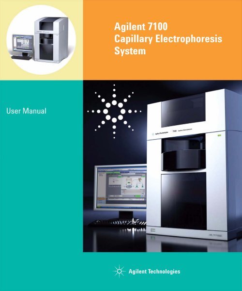
<strong>Agilent</strong> <strong>7100</strong><br />
<strong>Capillary</strong> <strong>Electrophoresis</strong><br />
<strong>System</strong><br />
User Manual<br />
<strong>Agilent</strong> Technologies
Notices<br />
© <strong>Agilent</strong> Technologies, Inc. 2009<br />
No part of this manual may be reproduced in<br />
any form or by any means (including electronic<br />
s<strong>to</strong>rage and retrieval or translation<br />
in<strong>to</strong> a foreign language) without prior agreement<br />
and written consent from <strong>Agilent</strong><br />
Technologies, Inc. as governed by United<br />
States and international copyright laws.<br />
Manual Part Number<br />
G<strong>7100</strong>-90000<br />
Edition<br />
12/2009<br />
Printed in Germany<br />
<strong>Agilent</strong> Technologies, Deutschland GmbH<br />
Hewlett-Packard-Strasse 8<br />
76337 Waldbronn<br />
Warranty<br />
The material contained in this document<br />
is provided “as is,” and is subject<br />
<strong>to</strong> being changed, without notice,<br />
in future editions. Fur<strong>the</strong>r, <strong>to</strong> <strong>the</strong> maximum<br />
extent permitted by applicable<br />
law, <strong>Agilent</strong> disclaims all warranties,<br />
ei<strong>the</strong>r express or implied, with regard<br />
<strong>to</strong> this manual and any information<br />
contained herein, including but not<br />
limited <strong>to</strong> <strong>the</strong> implied warranties of<br />
merchantability and fitness for a particular<br />
purpose. <strong>Agilent</strong> shall not be<br />
liable for errors or for incidental or<br />
consequential damages in connection<br />
with <strong>the</strong> furnishing, use, or performance<br />
of this document or of any<br />
information contained herein. Should<br />
<strong>Agilent</strong> and <strong>the</strong> user have a separate<br />
written agreement with warranty<br />
terms covering <strong>the</strong> material in this<br />
document that conflict with <strong>the</strong>se<br />
terms, <strong>the</strong> warranty terms in <strong>the</strong> separate<br />
agreement shall control.<br />
Technology Licenses<br />
The hardware and/or software described in<br />
this document are furnished under a license<br />
and may be used or copied only in accordance<br />
with <strong>the</strong> terms of such license.<br />
Restricted Rights Legend<br />
If software is for use in <strong>the</strong> performance of a<br />
U.S. Government prime contract or subcontract,<br />
Software is delivered and licensed as<br />
“Commercial computer software” as<br />
defined in DFAR 252.227-7014 (June 1995),<br />
or as a “commercial item” as defined in FAR<br />
2.101(a) or as “Restricted computer software”<br />
as defined in FAR 52.227-19 (June<br />
1987) or any equivalent agency regulation or<br />
contract clause. Use, duplication or disclosure<br />
of Software is subject <strong>to</strong> <strong>Agilent</strong> Technologies’<br />
standard commercial license<br />
terms, and non-DOD Departments and<br />
Agencies of <strong>the</strong> U.S. Government will<br />
receive no greater than Restricted Rights as<br />
defined in FAR 52.227-19(c)(1-2) (June<br />
1987). U.S. Government users will receive<br />
no greater than Limited Rights as defined in<br />
FAR 52.227-14 (June 1987) or DFAR<br />
252.227-7015 (b)(2) (November 1995), as<br />
applicable in any technical data.<br />
Safety Notices<br />
CAUTION<br />
A CAUTION notice denotes a hazard.<br />
It calls attention <strong>to</strong> an operating<br />
procedure, practice, or <strong>the</strong> like<br />
that, if not correctly performed or<br />
adhered <strong>to</strong>, could result in damage<br />
<strong>to</strong> <strong>the</strong> product or loss of important<br />
data. Do not proceed beyond a<br />
CAUTION notice until <strong>the</strong> indicated<br />
conditions are fully unders<strong>to</strong>od and<br />
met.<br />
WARNING<br />
A WARNING notice denotes a<br />
hazard. It calls attention <strong>to</strong> an<br />
operating procedure, practice, or<br />
<strong>the</strong> like that, if not correctly performed<br />
or adhered <strong>to</strong>, could result<br />
in personal injury or death. Do not<br />
proceed beyond a WARNING<br />
notice until <strong>the</strong> indicated conditions<br />
are fully unders<strong>to</strong>od and<br />
met.<br />
Research Use Only<br />
<strong>Agilent</strong> <strong>7100</strong> <strong>Capillary</strong> <strong>Electrophoresis</strong> <strong>System</strong>
In This Guide…<br />
This guide contains information <strong>to</strong> install and operate <strong>the</strong><br />
<strong>Agilent</strong> <strong>7100</strong> <strong>Capillary</strong> <strong>Electrophoresis</strong> <strong>System</strong>.<br />
1 <strong>Introduction</strong><br />
This chapter gives an introduction <strong>to</strong> <strong>the</strong> instrument,<br />
instrument overview and internal connec<strong>to</strong>rs.<br />
2 Site Requirements and Specifications<br />
This chapter provides information on environmental<br />
requirements, physical and performance specifications.<br />
3 Installing <strong>the</strong> Instrument<br />
In this chapter you will find information about how <strong>to</strong> unpack<br />
and <strong>to</strong> set up <strong>the</strong> <strong>Agilent</strong> CE and information about <strong>the</strong><br />
configuration of Instrument.<br />
4 LAN Configuration<br />
This chapter provides information on connecting <strong>the</strong> CE<br />
instrument <strong>to</strong> <strong>the</strong> <strong>Agilent</strong> ChemStation PC.<br />
5 Using <strong>the</strong> <strong>Agilent</strong> <strong>7100</strong> <strong>Capillary</strong> <strong>Electrophoresis</strong> <strong>System</strong><br />
This chapter provides information on how <strong>to</strong> set up <strong>the</strong> CE<br />
instrument for an analysis and explains <strong>the</strong> basic settings.<br />
6 Troubleshooting and Diagnostics<br />
This chapter gives an overview about <strong>the</strong> troubleshooting and<br />
diagnostic features and <strong>the</strong> different user interfaces.<br />
7 Hardware Information<br />
This chapter describes <strong>the</strong> instrument in more detail on<br />
hardware and electronics.<br />
8 Maintenance<br />
This chapter describes <strong>the</strong> maintenance of <strong>the</strong> CE instrument.<br />
<strong>Agilent</strong> <strong>7100</strong> <strong>Capillary</strong> <strong>Electrophoresis</strong> <strong>System</strong> User Manual 3
9 Parts and Materials for Maintenance<br />
This chapter provides information on parts for maintenance.<br />
10 Appendix<br />
This chapter provides additional information on safety, legal<br />
and web content associated with your <strong>7100</strong> CE instrument.<br />
4 <strong>Agilent</strong> <strong>7100</strong> <strong>Capillary</strong> <strong>Electrophoresis</strong> <strong>System</strong> User Manual
Contents<br />
1 <strong>Introduction</strong> 13<br />
<strong>Introduction</strong> <strong>to</strong> <strong>the</strong> <strong>Agilent</strong> <strong>7100</strong> <strong>Capillary</strong> <strong>Electrophoresis</strong> <strong>System</strong> 14<br />
Getting Help 14<br />
Where <strong>to</strong> Find Information 15<br />
What Learning Products are Available? 16<br />
2 Site Requirements and Specifications 17<br />
Site Requirements 18<br />
Power Consideration 18<br />
Power Cords 19<br />
Bench Space 20<br />
Environment 20<br />
Physical Specifications 21<br />
Performance Specifications 22<br />
Anforderungen an den Aufstellungsort 23<br />
Stromversorgung 23<br />
Netzkabel 24<br />
Platzbedarf 25<br />
Umgebungsbedingungen 25<br />
Abmessungen und Gewicht 26<br />
Leistungsspezifikationen 27<br />
Exigences d’installation 28<br />
Remarques à propos de l’alimentation 28<br />
Câbles d’alimentation 29<br />
Encombrement 30<br />
Environnement 30<br />
Caractéristiques physiques 31<br />
Caractéristiques de performance 32<br />
<strong>Agilent</strong> <strong>7100</strong> <strong>Capillary</strong> <strong>Electrophoresis</strong> <strong>System</strong> User Manual 5
Contents<br />
Requisiti ambientali 33<br />
Alimentazione 33<br />
Cavi di alimentazione 34<br />
Spazio necessario 35<br />
Ambiente 35<br />
Specifiche fisiche 36<br />
Specifiche delle prestazioni 37<br />
Requisi<strong>to</strong>s de las instalaciones 38<br />
Consideraciones sobre la corriente 38<br />
Cables de alimentación 39<br />
Espacio en el banco 40<br />
En<strong>to</strong>rno 40<br />
Especificaciones físicas 41<br />
Especificaciones de rendimien<strong>to</strong> 42<br />
設 置 について 43<br />
電 源 について 43<br />
電 源 コード 44<br />
作 業 台 スペース 45<br />
環 境 条 件 45<br />
物 理 的 仕 様 46<br />
性 能 仕 様 47<br />
场 地 要 求 48<br />
电 源 要 求 48<br />
电 源 线 49<br />
工 作 台 位 置 50<br />
环 境 50<br />
物 理 规 格 51<br />
性 能 规 格 52<br />
3 Installing <strong>the</strong> Instrument 53<br />
Unpacking <strong>the</strong> <strong>Agilent</strong> CE Instrument 54<br />
Damaged Packaging 54<br />
Unpacking <strong>the</strong> CE Instrument 54<br />
6 <strong>Agilent</strong> <strong>7100</strong> <strong>Capillary</strong> <strong>Electrophoresis</strong> <strong>System</strong> User Manual
Contents<br />
Delivery Checklist 55<br />
Installing <strong>the</strong> Instrument 57<br />
Physical Connection 57<br />
4 LAN Configuration 61<br />
What You Have <strong>to</strong> Do First 62<br />
TCP/IP Parameter Configuration 63<br />
Configuration Switch 64<br />
Initialization Mode Selection 65<br />
Link Configuration Selection 69<br />
S<strong>to</strong>ring <strong>the</strong> Settings Permanently with Bootp 70<br />
Manual Configuration 71<br />
With Telnet 72<br />
<strong>Agilent</strong> Bootp Service 75<br />
Location of <strong>the</strong> Media Access Control (MAC) Address 76<br />
5 Using <strong>the</strong> <strong>Agilent</strong> <strong>7100</strong> <strong>Capillary</strong> <strong>Electrophoresis</strong> <strong>System</strong> 77<br />
<strong>System</strong> Definition 78<br />
Controlling <strong>the</strong> <strong>Agilent</strong> CE Instrument 79<br />
Before You Start <strong>the</strong> <strong>Agilent</strong> CE Instrument 79<br />
Starting Up <strong>the</strong> <strong>Agilent</strong> CE Instrument 79<br />
Starting Your Computer and <strong>the</strong> <strong>Agilent</strong> ChemStation Software 81<br />
Starting <strong>the</strong> <strong>Agilent</strong> ChemStation Software <strong>the</strong> First Time 82<br />
Working with <strong>the</strong> CE Diagram 84<br />
Common Software Toolbar 84<br />
Software Toolbar 85<br />
Graphical User Interface Explanation 86<br />
Menus in <strong>the</strong> CE and DAD Diagram 88<br />
<strong>System</strong> Vialtable 90<br />
How <strong>to</strong> Prepare your <strong>Agilent</strong> CE Instrument for Analysis 91<br />
<strong>Capillary</strong> <strong>Electrophoresis</strong>, CE 92<br />
How <strong>to</strong> Use Your <strong>Agilent</strong> CE Instrument for <strong>Capillary</strong> <strong>Electrophoresis</strong><br />
Separations 92<br />
<strong>Agilent</strong> <strong>7100</strong> <strong>Capillary</strong> <strong>Electrophoresis</strong> <strong>System</strong> User Manual 7
Contents<br />
<strong>Agilent</strong> CE Method Parameters 92<br />
Vials 96<br />
Cassette Temperature 97<br />
High Voltage <strong>System</strong> 98<br />
Posttime and S<strong>to</strong>ptime 100<br />
Replenishment 100<br />
Preconditioning 101<br />
Injection 103<br />
Timetable 105<br />
Detec<strong>to</strong>r Parameters 107<br />
Switching <strong>the</strong> Lamp On 110<br />
Preparing <strong>the</strong> Replenishment <strong>System</strong> if Needed 111<br />
Preparing Vials for Buffer and Sample 115<br />
Installing a <strong>Capillary</strong> in <strong>the</strong> Alignment Interface 124<br />
Installing a <strong>Capillary</strong> in an Empty <strong>Capillary</strong> Cassette 128<br />
Inserting <strong>the</strong> Cassette 132<br />
Fraction Collection 135<br />
<strong>Capillary</strong> <strong>Electrophoresis</strong>, Plus High Pressure CE+p 136<br />
Requirements 136<br />
Outlet Lift Connection <strong>to</strong> <strong>the</strong> Tubing <strong>System</strong> 138<br />
Preparing <strong>the</strong> <strong>Agilent</strong> CE Instrument for High Pressure Use 140<br />
Operation and Function in CE+p Mode 143<br />
Injection Options with CE+p 146<br />
Timetable Options with CE+p 146<br />
CE+p Control Using <strong>the</strong> CE Diagram 147<br />
<strong>Capillary</strong> Electrochroma<strong>to</strong>graphy, CEC 148<br />
How <strong>to</strong> Use Your <strong>Agilent</strong> CE Instrument for <strong>Capillary</strong><br />
Electrochroma<strong>to</strong>graphy 148<br />
Preparing <strong>the</strong> <strong>Agilent</strong> CE Instrument for High Pressure Use 150<br />
CEC-Specific GUI Explanation 153<br />
Injection Options with CEC 156<br />
Timetable Options with CEC 157<br />
CEC Control Using <strong>the</strong> CE Diagram 158<br />
8 <strong>Agilent</strong> <strong>7100</strong> <strong>Capillary</strong> <strong>Electrophoresis</strong> <strong>System</strong> User Manual
Contents<br />
Running <strong>the</strong> CEC Analysis 159<br />
6 Troubleshooting and Diagnostics 161<br />
CE Problem Solving 162<br />
Power On Fail 162<br />
Leaks 163<br />
Blocked Replenishment Needle 165<br />
Leakage Current 165<br />
Broken <strong>Capillary</strong> 166<br />
Contaminated Insulation Plate 166<br />
Empty Injection Vial 167<br />
Dirt in <strong>the</strong> Vials 167<br />
Air Bubble in Injection Vial or Run Buffer Vials 167<br />
Air Bubble in <strong>Capillary</strong> 167<br />
Problems with <strong>the</strong> Replenishment <strong>System</strong> and Buffers<br />
Containing SDS 168<br />
<strong>Agilent</strong> Lab Advisor Software 169<br />
Configuration 169<br />
7 Hardware Information 171<br />
Identifying Instrument Components 172<br />
<strong>7100</strong> <strong>Capillary</strong> <strong>Electrophoresis</strong> Instrument Electronics 173<br />
Firmware 176<br />
Resident <strong>System</strong> 176<br />
Main <strong>System</strong> 176<br />
Firmware Updates 177<br />
Diode Array Detec<strong>to</strong>r 179<br />
DAD Control 180<br />
Digital <strong>to</strong> Analog Converter 181<br />
Changing <strong>the</strong> Fuses for <strong>the</strong> Power Supplies 182<br />
Installing Drainage Tubing 183<br />
External Water Bath for Tray Cooling (Optional) 184<br />
Analog <strong>to</strong> Digital Converter 186<br />
<strong>Agilent</strong> <strong>7100</strong> <strong>Capillary</strong> <strong>Electrophoresis</strong> <strong>System</strong> User Manual 9
Contents<br />
8 Maintenance 189<br />
Standard Operating Procedures for Maintenance of Your<br />
<strong>Agilent</strong> CE Instrument 190<br />
Overview of Maintenance 191<br />
Early Maintenance Feedback (EMF) 194<br />
EMF Counters 194<br />
Using <strong>the</strong> EMF Counters 194<br />
Setting <strong>the</strong> EMF Limits 195<br />
Cleaning <strong>the</strong> Electrodes, Pre-punchers and Insulation Plate 196<br />
Prepare <strong>the</strong> <strong>Agilent</strong> CE Instrument 197<br />
Remove <strong>the</strong> Covers 198<br />
Accessing <strong>the</strong> Electrodes 199<br />
Accessing <strong>the</strong> Liquid Handling Module 201<br />
Accessing and Removing <strong>the</strong> Pre-punchers 203<br />
Cleaning <strong>the</strong> Electrodes 205<br />
Cleaning <strong>the</strong> Pre-punchers 206<br />
Cleaning <strong>the</strong> Insulation Plate 207<br />
Reinstalling <strong>the</strong> Pre-punchers 208<br />
Reinstalling <strong>the</strong> Electrodes and <strong>the</strong> Insulation Plate 210<br />
Reinstall <strong>the</strong> <strong>Capillary</strong> Cassette 215<br />
Reinstall <strong>the</strong> Front Cover 215<br />
Maintenance of <strong>the</strong> Replenishment <strong>System</strong> 216<br />
Changing <strong>the</strong> Buffer Composition in <strong>the</strong> Replenishment <strong>System</strong> 217<br />
The Replenishment <strong>System</strong> Will Not Be Used for Some Time 218<br />
Fur<strong>the</strong>r Action 219<br />
Operations for Replenishment Maintenance 219<br />
Changing <strong>the</strong> Air Inlet Filter 222<br />
Accessing <strong>the</strong> Air Filter 222<br />
Changing <strong>the</strong> Lamp 224<br />
Removing <strong>the</strong> Existing Lamp 225<br />
Inserting a New Lamp 227<br />
Fur<strong>the</strong>r Action 227<br />
Cleaning <strong>the</strong> Instrument 228<br />
10 <strong>Agilent</strong> <strong>7100</strong> <strong>Capillary</strong> <strong>Electrophoresis</strong> <strong>System</strong> User Manual
Contents<br />
9 Parts and Materials for Maintenance 229<br />
Overview of Maintenance Parts 230<br />
10 Appendix 231<br />
General Safety Information 232<br />
Operation 232<br />
Allgemeine Sicherheitsinformation 235<br />
Informations générales de sécurité 238<br />
Informazioni generali sulla sicurezza 241<br />
Información de seguridad 244<br />
安 全 に 関 する 一 般 的 な 情 報 247<br />
一 般 安 全 信 息 250<br />
Setting Up a Test Sample Run 252<br />
Method Parameter CE (Default Settings) 253<br />
Method Parameter DAD 255<br />
Chemical and Biological Safety 256<br />
The Waste Electrical and Electronic Equipment (WEEE) Directive<br />
(2002/96/EC) 257<br />
Radio Interference 258<br />
Sound Emission 259<br />
Legal Notice 260<br />
<strong>Agilent</strong> Technologies on Internet 261<br />
Index 263<br />
<strong>Agilent</strong> <strong>7100</strong> <strong>Capillary</strong> <strong>Electrophoresis</strong> <strong>System</strong> User Manual 11
Contents<br />
12 <strong>Agilent</strong> <strong>7100</strong> <strong>Capillary</strong> <strong>Electrophoresis</strong> <strong>System</strong> User Manual
<strong>Agilent</strong> <strong>7100</strong> <strong>Capillary</strong> <strong>Electrophoresis</strong> <strong>System</strong><br />
User Manual<br />
1<br />
<strong>Introduction</strong><br />
<strong>Introduction</strong> <strong>to</strong> <strong>the</strong> <strong>Agilent</strong> <strong>7100</strong> <strong>Capillary</strong> <strong>Electrophoresis</strong> <strong>System</strong> 14<br />
Where <strong>to</strong> Find Information 15<br />
What Learning Products are Available? 16<br />
This chapter gives an introduction <strong>to</strong> <strong>the</strong> <strong>Agilent</strong> <strong>7100</strong> <strong>Capillary</strong><br />
<strong>Electrophoresis</strong> <strong>System</strong> and where <strong>to</strong> find specific information or help.<br />
<strong>Agilent</strong> Technologies<br />
13
1 <strong>Introduction</strong><br />
<strong>Introduction</strong> <strong>to</strong> <strong>the</strong> <strong>Agilent</strong> <strong>7100</strong> <strong>Capillary</strong> <strong>Electrophoresis</strong> <strong>System</strong><br />
<strong>Introduction</strong> <strong>to</strong> <strong>the</strong> <strong>Agilent</strong> <strong>7100</strong> <strong>Capillary</strong> <strong>Electrophoresis</strong><br />
<strong>System</strong><br />
This handbook gives an overview of your <strong>Agilent</strong> <strong>7100</strong> <strong>Capillary</strong><br />
<strong>Electrophoresis</strong> <strong>System</strong>. It is designed <strong>to</strong> get you started working with <strong>the</strong><br />
system. We strongly advise you <strong>to</strong> make extensive use of <strong>the</strong> online help when<br />
working with <strong>the</strong> system. There you find detailed reference and task<br />
information which complements <strong>the</strong> overview given in this guide. Refer <strong>to</strong><br />
“Getting Help” later in this section for information on using <strong>the</strong> online help of<br />
<strong>the</strong> ChemStation. Refer <strong>to</strong> “Where <strong>to</strong> Find Information” for help in finding<br />
information on certain tasks.<br />
Getting Help<br />
You can get help by choosing <strong>the</strong> Help item from <strong>the</strong> <strong>to</strong>p menu. This puts you<br />
in<strong>to</strong> <strong>the</strong> help index. From <strong>the</strong>re you can browse through <strong>the</strong> information by<br />
selecting <strong>the</strong> appropriate jumps (underlined words). To access specific<br />
information in <strong>the</strong> help:<br />
When you are in <strong>the</strong> <strong>Agilent</strong> ChemStation or Lab Advisor software:<br />
• select a context-sensitive element and press F1.<br />
When you are in <strong>the</strong> online help:<br />
• search for a specific keyword using <strong>the</strong> search command,<br />
• select a jump - a jump is an underlined word you can select <strong>to</strong> go <strong>to</strong> a <strong>to</strong>pic<br />
related <strong>to</strong> <strong>the</strong> word, or<br />
• select a word or phrase with a dotted underline <strong>to</strong> see its definition. The<br />
online help also contains online information on how <strong>to</strong> use help.<br />
14 <strong>Agilent</strong> <strong>7100</strong> <strong>Capillary</strong> <strong>Electrophoresis</strong> <strong>System</strong> User Manual
<strong>Introduction</strong> 1<br />
Where <strong>to</strong> Find Information<br />
Where <strong>to</strong> Find Information<br />
Table 1<br />
Where <strong>to</strong> find information<br />
Task<br />
• Installation of <strong>the</strong> <strong>Agilent</strong> CE <strong>System</strong>,<br />
installing <strong>the</strong> external water bath,<br />
installing <strong>the</strong> high sensitivity cell<br />
• Setting up <strong>the</strong> <strong>Agilent</strong> CE <strong>System</strong> for<br />
CE analysis, CE+p<br />
• How <strong>to</strong> use <strong>the</strong> <strong>Agilent</strong> CE <strong>System</strong> in<br />
<strong>the</strong> CE+p mode<br />
• How <strong>to</strong> use <strong>the</strong> <strong>Agilent</strong> CE <strong>System</strong> for<br />
capillary electrochroma<strong>to</strong>graphy<br />
• How <strong>to</strong> maintain <strong>the</strong> <strong>Agilent</strong> CE<br />
<strong>System</strong><br />
Refer <strong>to</strong><br />
"The Core <strong>Agilent</strong> CE Instrument" “Installing <strong>the</strong><br />
Instrument” on page 53<br />
Chapter “Using <strong>the</strong> <strong>Agilent</strong> <strong>7100</strong> <strong>Capillary</strong><br />
<strong>Electrophoresis</strong> <strong>System</strong>” on page 77"<br />
“<strong>Capillary</strong> <strong>Electrophoresis</strong>, Plus High Pressure<br />
CE+p” on page 136<br />
“<strong>Capillary</strong> Electrochroma<strong>to</strong>graphy, CEC” on page 148<br />
Chapter “Maintenance” on page 189<br />
• Setting up a sequence Online help "Understanding Your ChemStation"<br />
• Data analysis Online help "Understanding Your ChemStation"<br />
• Setting up a report Online help "Understanding Your ChemStation"<br />
• Spectral library search “ChemStation Applications” handbook and online help<br />
• Setting up cus<strong>to</strong>mized reports “ChemStation Applications” handbook<br />
• Safety information Safety information in “Appendix” on page 231<br />
• Learning ChemStation concepts “Understanding Your ChemStation” handbook<br />
• Learning <strong>the</strong> <strong>the</strong>ory of <strong>the</strong> technique High Performance <strong>Capillary</strong> <strong>Electrophoresis</strong>: An<br />
<strong>Introduction</strong>”<br />
The CE Partner CD-ROM: “The comprehensive,<br />
interactive <strong>to</strong>ol for beginners and advanced users of<br />
CE”<br />
• Application <strong>Agilent</strong> web page (http://www.agilent.com), search for<br />
Application notes<br />
<strong>Agilent</strong> <strong>7100</strong> <strong>Capillary</strong> <strong>Electrophoresis</strong> <strong>System</strong> User Manual 15
1 <strong>Introduction</strong><br />
What Learning Products are Available?<br />
What Learning Products are Available?<br />
The <strong>Agilent</strong> CE <strong>System</strong> is supplied with <strong>the</strong> following:<br />
• User's Guide<br />
• High Performance <strong>Capillary</strong> <strong>Electrophoresis</strong>: An <strong>Introduction</strong><br />
The <strong>Agilent</strong> ChemStation and Lab Advisor/Instrument Utilities software DVD<br />
is supplied with <strong>the</strong> following electronic documents:<br />
• Installing Your <strong>Agilent</strong> ChemStation for LC and CE <strong>System</strong>s<br />
• Installing and Understanding Your Spectra Module<br />
• Understanding Your <strong>Agilent</strong> ChemStation<br />
• Online help<br />
• Understanding Your <strong>Agilent</strong> ChemStation for CE <strong>System</strong>s<br />
16 <strong>Agilent</strong> <strong>7100</strong> <strong>Capillary</strong> <strong>Electrophoresis</strong> <strong>System</strong> User Manual
<strong>Agilent</strong> <strong>7100</strong> <strong>Capillary</strong> <strong>Electrophoresis</strong> <strong>System</strong><br />
User Manual<br />
2<br />
Site Requirements and Specifications<br />
Site Requirements 18<br />
Physical Specifications 21<br />
Performance Specifications 22<br />
Anforderungen an den Aufstellungsort 23<br />
Abmessungen und Gewicht 26<br />
Leistungsspezifikationen 27<br />
Exigences d’installation 28<br />
Caractéristiques physiques 31<br />
Caractéristiques de performance 32<br />
Requisiti ambientali 33<br />
Specifiche fisiche 36<br />
Specifiche delle prestazioni 37<br />
Requisi<strong>to</strong>s de las instalaciones 38<br />
Especificaciones físicas 41<br />
Especificaciones de rendimien<strong>to</strong> 42<br />
設 置 について 43<br />
物 理 的 仕 様 46<br />
性 能 仕 様 47<br />
场 地 要 求 48<br />
物 理 规 格 51<br />
性 能 规 格 52<br />
This chapter provides information on <strong>the</strong> environmental requirements, as well<br />
as physical and performance specifications.<br />
<strong>Agilent</strong> Technologies<br />
17
2 Site Requirements and Specifications<br />
Site Requirements<br />
Site Requirements<br />
A suitable environment is important <strong>to</strong> ensure optimal performance of <strong>the</strong><br />
<strong>7100</strong> <strong>Capillary</strong> <strong>Electrophoresis</strong> instrument.<br />
Before you begin installation, check carefully that <strong>the</strong> place you have chosen<br />
meets <strong>the</strong> requirements below.<br />
Power Consideration<br />
The instrument power supply has wide ranging capabilities and accepts any<br />
standard line voltage in <strong>the</strong> range mentioned in Table 2 on page 21.<br />
Consequently, <strong>the</strong>re is no voltage selec<strong>to</strong>r on <strong>the</strong> back of <strong>the</strong> detec<strong>to</strong>r.<br />
WARNING<br />
The module is partially energized when switched off, as long as <strong>the</strong> power cord is<br />
plugged in.<br />
Repair or maintenance work on <strong>the</strong> module can lead <strong>to</strong> personal injuries, for<br />
example a shock hazard, when <strong>the</strong> cover is opened and <strong>the</strong> module is connected <strong>to</strong><br />
<strong>the</strong> power.<br />
• Make sure that it is always possible <strong>to</strong> access <strong>the</strong> power plug.<br />
• Remove <strong>the</strong> power cable from <strong>the</strong> instrument before opening <strong>the</strong> cover.<br />
• Do not connect <strong>the</strong> power cable <strong>to</strong> <strong>the</strong> instrument while <strong>the</strong> electronic box in <strong>the</strong><br />
back of <strong>the</strong> instrument is opened or side panels are removed.<br />
WARNING<br />
Incorrect line voltage on <strong>the</strong> instrument<br />
Shock hazard or damage <strong>to</strong> your instrument can result if <strong>the</strong> device is connected <strong>to</strong> a<br />
line voltage that is higher than specified.<br />
• Connect your instrument <strong>to</strong> <strong>the</strong> specified line voltage.<br />
18 <strong>Agilent</strong> <strong>7100</strong> <strong>Capillary</strong> <strong>Electrophoresis</strong> <strong>System</strong> User Manual
Site Requirements and Specifications 2<br />
Site Requirements<br />
CAUTION<br />
Inaccessible power plug.<br />
In <strong>the</strong> case of an emergency it must be possible <strong>to</strong> disconnect <strong>the</strong> instrument from <strong>the</strong><br />
power line at any time.<br />
• Make sure <strong>the</strong> power connec<strong>to</strong>r of <strong>the</strong> instrument can be easily reached and<br />
unplugged.<br />
• Provide sufficient space behind <strong>the</strong> power socket of <strong>the</strong> instrument <strong>to</strong> unplug <strong>the</strong><br />
cable.<br />
Power Cords<br />
Different power cords are delivered with <strong>the</strong> instrument. The female end of all<br />
power cords is identical. It plugs in<strong>to</strong> <strong>the</strong> power-input socket at <strong>the</strong> rear. The<br />
male end of each power cord is different and designed <strong>to</strong> match <strong>the</strong> wall socket<br />
of a particular country or region.<br />
WARNING<br />
Absence of a ground connection or use of an unspecified power cord<br />
The absence of a ground connection or <strong>the</strong> use of an unspecified power cord can<br />
lead <strong>to</strong> an electric shock or short circuit.<br />
• Never operate your instrument from a power outlet without a ground connection.<br />
• Never use a power cord o<strong>the</strong>r than <strong>the</strong> <strong>Agilent</strong> Technologies power cord designed<br />
for your region.<br />
WARNING<br />
Use of unsupplied cables<br />
Using cables not supplied by <strong>Agilent</strong> Technologies can lead <strong>to</strong> damage of <strong>the</strong><br />
electronic components or personal injury.<br />
• Never use cables o<strong>the</strong>r than <strong>the</strong> ones supplied by <strong>Agilent</strong> Technologies <strong>to</strong> ensure<br />
proper functionality and compliance with safety or EMC regulations.<br />
<strong>Agilent</strong> <strong>7100</strong> <strong>Capillary</strong> <strong>Electrophoresis</strong> <strong>System</strong> User Manual 19
2 Site Requirements and Specifications<br />
Site Requirements<br />
Bench Space<br />
The instrument dimensions and weight mean that <strong>the</strong> instrument can be<br />
placed on almost any desk or labora<strong>to</strong>ry bench. It needs an additional 2.5 cm<br />
(1.0 inch) of space on ei<strong>the</strong>r side and approximately 8 cm (3.1 inches) in <strong>the</strong><br />
rear for air circulation and electric connections.<br />
If <strong>the</strong> <strong>Agilent</strong> <strong>7100</strong> <strong>Capillary</strong> <strong>Electrophoresis</strong> instrument is <strong>to</strong> be placed on a<br />
bench, make sure that <strong>the</strong> bench is designed <strong>to</strong> bear <strong>the</strong> weight of <strong>the</strong> system.<br />
The instrument must be operated in a upright position.<br />
Environment<br />
Your instrument will work within <strong>the</strong> specifications for ambient temperatures<br />
and relative humidity described in Table 2 on page 21.<br />
CAUTION<br />
Condensation within <strong>the</strong> module<br />
Condensation will damage <strong>the</strong> system electronics.<br />
• Do not s<strong>to</strong>re, ship or use your module under conditions where temperature<br />
fluctuations could cause condensation within <strong>the</strong> module.<br />
• If your module was shipped in cold wea<strong>the</strong>r, leave it in its box and allow it <strong>to</strong> warm<br />
slowly <strong>to</strong> room temperature <strong>to</strong> avoid condensation.<br />
20 <strong>Agilent</strong> <strong>7100</strong> <strong>Capillary</strong> <strong>Electrophoresis</strong> <strong>System</strong> User Manual
Site Requirements and Specifications 2<br />
Physical Specifications<br />
Physical Specifications<br />
Table 2<br />
Physical specifications<br />
Type Specification Comments<br />
Weight<br />
Dimensions<br />
(width × depth × height)<br />
35 kg (77.2 lbs)<br />
350 x 510 x 590 mm<br />
(13.8 x 20.1 x 23.2 inches)<br />
Line voltage 100–240 VAC ± 10% Wide-ranging capability<br />
Line frequency 50 or 60 Hz ± 5%<br />
Power consumption 350 VA / 300 W / 1024 BTU/h Maximum<br />
Ambient operating<br />
temperature<br />
Ambient non-operating<br />
temperature<br />
5–40 °C (41–104 °F)<br />
-40 <strong>to</strong> 70°C (-40 <strong>to</strong> 158 °F)<br />
Humidity below 80% at 31 °C (87.8 °F) Non-condensing<br />
Operating altitude<br />
External cooling<br />
Up <strong>to</strong> 2000 m (6500 ft)<br />
max. 0.5 bar (7.2 psi),<br />
max. 50 °C (122 °F)<br />
Waterbath<br />
External pressure 2-12 bar (29-174 psi) Oil-free air or nitrogen<br />
Safety standards: IEC,<br />
CSA, UL<br />
Housing<br />
Installation category II,<br />
Pollution degree 2<br />
All materials are recyclable<br />
For indoor use only<br />
For applications run in CEC mode (<strong>Capillary</strong> Electrochroma<strong>to</strong>graphy) or CE+p<br />
mode (<strong>Capillary</strong> <strong>Electrophoresis</strong> mode with optional usage of higher pressure), an<br />
external pressure supply of oil-free air or nitrogen with a maximum pressure of 15<br />
bar (218 psi) can be used. A respective male adapter that fits in<strong>to</strong> <strong>the</strong> instrument’s<br />
female adapter and PTFE tubing are part of <strong>the</strong> shipment.<br />
NOTE<br />
The <strong>Agilent</strong> <strong>7100</strong> <strong>Capillary</strong> <strong>Electrophoresis</strong> <strong>System</strong> is designed <strong>to</strong> operate in a typical<br />
electromagnetic environment where RF transmitters, such as mobile phones, should not be<br />
used in close proximity.<br />
<strong>Agilent</strong> <strong>7100</strong> <strong>Capillary</strong> <strong>Electrophoresis</strong> <strong>System</strong> User Manual 21
2 Site Requirements and Specifications<br />
Performance Specifications<br />
Performance Specifications<br />
Table 3<br />
Performance specifications for <strong>the</strong> <strong>Agilent</strong> <strong>7100</strong> <strong>Capillary</strong> <strong>Electrophoresis</strong> <strong>System</strong><br />
Type Specification Comments<br />
Safety features<br />
Control and data evaluation<br />
Communication<br />
GLP features<br />
Extensive diagnostics, error detection and display,<br />
current leak detection; low current limit<br />
Liquid leak sensor; safety sensors on door and<br />
cover disabling high voltage; vial sensor;<br />
<strong>Agilent</strong> ChemStation under Windows® XP (SP3)<br />
LAN, controller-area network (CAN), RS-232C,<br />
APG remote: ready, start, s<strong>to</strong>p and shut-down<br />
signals. USB (future use).<br />
Analog out and in.<br />
Early maintenance feedback (EMF), electronic<br />
records of maintenance and errors<br />
0 <strong>to</strong>1 V<br />
22 <strong>Agilent</strong> <strong>7100</strong> <strong>Capillary</strong> <strong>Electrophoresis</strong> <strong>System</strong> User Manual
Site Requirements and Specifications 2<br />
Anforderungen an den Aufstellungsort<br />
Anforderungen an den Aufstellungsort<br />
Eine geeignete Umgebung ist wichtig für die optimale Leistungsfähigkeit<br />
des <strong>7100</strong> Kapillarelektrophorese-Geräts.<br />
Prüfen Sie sorgfältig, ob der von Ihnen gewählte Aufstellort die nachfolgenden<br />
Anforderungen erfüllt, bevor Sie mit der Installation beginnen.<br />
Stromversorgung<br />
Das Weitbereichsnetzteil des Geräts arbeitet mit Standard-Netzspannungen<br />
gemäß den Angaben in Tabelle 4 auf Seite 26. Daher ist an der Rückseite<br />
des Detek<strong>to</strong>rs kein Spannungswahlschalter vorhanden.<br />
WARNUNG<br />
Auch im ausgeschalteten Zustand fließt im Modul Strom, solange das Netzkabel<br />
eingesteckt ist.<br />
Die Durchführung von Reparatur- oder Wartungsarbeiten am Modul kann zu<br />
Personenschäden wie z. B. durch Stromschlag führen, wenn das Modulgehäuse<br />
geöffnet wird, während das Modul an die Netzspannung angeschlossen ist.<br />
• Stellen Sie den freien Zugang zu den Netzkabeln sicher.<br />
• Trennen Sie das Netzkabel vom Gerät, bevor Sie das Gehäuse öffnen.<br />
• Schließen Sie das Netzkabel nicht an das Gerät an, während der Elektronikkasten<br />
an der Geräterückseite geöffnet oder Seitenteile entfernt sind.<br />
WARNUNG<br />
Falsche Netzspannung am Gerät<br />
Wenn das Gerät an eine höhere Spannung als spezifiziert angeschlossen wird, kann<br />
dies zu Überspannungsschäden oder einer völligen Zerstörung des Geräts führen.<br />
• Schließen Sie das Gerät an die angegebene Netzspannung an.<br />
<strong>Agilent</strong> <strong>7100</strong> <strong>Capillary</strong> <strong>Electrophoresis</strong> <strong>System</strong> User Manual 23
2 Site Requirements and Specifications<br />
Anforderungen an den Aufstellungsort<br />
VORSICHT<br />
Unzugänglicher Netzstecker.<br />
In einem Notfall muss es jederzeit möglich sein, das Gerät vom Stromnetz zu trennen.<br />
• Stellen Sie sicher, dass der Netzstecker des Geräts leicht zugänglich ist.<br />
• Lassen Sie hinter der Netzbuchse des Geräts genügend Platz zum Herausziehen<br />
des Kabels.<br />
Netzkabel<br />
Das Gerät wird mit unterschiedlichen Netzkabeln ausgeliefert. Der weibliche<br />
Stecker ist bei jedem Netzkabel identisch. Er wird an die Netzanschlussbuchse<br />
an der Rückseite angeschlossen. Die Stecker am anderen Ende der Netzkabel<br />
sind unterschiedlich und erfüllen die Normen unterschiedlicher Länder oder<br />
Regionen.<br />
WARNUNG<br />
Nicht vorhandene Erdung oder Verwendung eines nicht spezifizierten Netzkabels<br />
Bei der Verwendung des Geräts ohne Erdung oder mit einem nicht spezifizierten<br />
Netzkabel können Stromschläge und Kurzschlüsse auftreten.<br />
• Betreiben Sie Ihr Gerät niemals an einer Spannungsquelle ohne Erdung.<br />
• Verwenden Sie niemals ein anderes als das von <strong>Agilent</strong> zum Einsatz im jeweiligen<br />
Land bereitgestellte Kabel.<br />
WARNUNG<br />
Verwendung nicht im Lieferumfang enthaltener Kabel<br />
Die Verwendung von Kabeln, die nicht von <strong>Agilent</strong> Technologies geliefert<br />
wurden, kann zu einer Beschädigung der elektronischen Komponenten oder<br />
zu Personenschäden führen.<br />
• Verwenden Sie ausschließlich Originalkabel von <strong>Agilent</strong> Technologies, um eine<br />
einwandfreie Funktion und die Einhaltung der Sicherheits- und EML-Bestimmungen<br />
zu gewährleisten.<br />
24 <strong>Agilent</strong> <strong>7100</strong> <strong>Capillary</strong> <strong>Electrophoresis</strong> <strong>System</strong> User Manual
Site Requirements and Specifications 2<br />
Anforderungen an den Aufstellungsort<br />
Platzbedarf<br />
Die Abmessungen und das Gewicht des Geräts ermöglichen seine Aufstellung<br />
auf praktisch jedem Schreibtisch oder Laborarbeitstisch. Das Gerät benötigt<br />
an jeder Seite zusätzlich 2,5 cm Platz und ungefähr 8 cm an der Rückseite<br />
für die elektrischen Anschlüsse und für eine ausreichende Luftzirkulation.<br />
Wenn das <strong>Agilent</strong> <strong>7100</strong> Kapillarelektrophorese <strong>System</strong> auf einem Labortisch<br />
aufgestellt werden soll, stellen Sie sicher, dass der Tisch ausreichende<br />
Tragfähigkeit für das <strong>System</strong> aufweist.<br />
Das Gerät ist stehend zu betreiben!<br />
Umgebungsbedingungen<br />
Ihr Gerät arbeitet bei der Umgebungstemperatur und der relativen<br />
Luftfeuchtigkeit, die in den Spezifikationen in Tabelle 4 auf Seite 26<br />
angegeben sind.<br />
VORSICHT<br />
Kondensation im Inneren des Moduls<br />
Kondensation führt zur Beschädigung der <strong>System</strong>elektronik.<br />
• Vermeiden Sie die Lagerung, den Versand oder den Betrieb der Pumpe unter<br />
Bedingungen, die zu einer Kondensation in der Pumpe führen können.<br />
• Nach einem Transport bei niedrigen Temperaturen muss das Gerät zur Vermeidung<br />
von Kondensation in der Verpackung verbleiben, bis es sich auf Raumtemperatur<br />
erwärmt hat.<br />
<strong>Agilent</strong> <strong>7100</strong> <strong>Capillary</strong> <strong>Electrophoresis</strong> <strong>System</strong> User Manual 25
2 Site Requirements and Specifications<br />
Abmessungen und Gewicht<br />
Abmessungen und Gewicht<br />
Tabelle 4<br />
Abmessungen und Gewicht<br />
Typ Spezifikationen Kommentare<br />
Gewicht<br />
Abmessungen<br />
(Breite × Tiefe × Höhe)<br />
35 kg<br />
350 x 510 x 590 mm<br />
(23,2 x 13,8 x 20,1 Zoll)<br />
Netzspannung 100–240 V Wechselstrom ± 10 % Weitbereichsnetzteil<br />
Netzfrequenz 50 oder 60 Hz ± 5 %<br />
Leistungsaufnahme 350 VA / 300 W / 1024 BTU/h Maximal<br />
zulässige<br />
Umgebungstemperatur<br />
bei Lagerung<br />
Umgebungstemperatur<br />
bei Lagerung<br />
5–40 °C<br />
-40 bis 70 °C<br />
Luftfeuchtigkeit unter 80 % bei 31 °C Nicht kondensierend<br />
Betriebshöhe<br />
bis zu 2000 m<br />
Externe Kühlung max. 0,5 bar (7,2 psi), max. 50 °C Wasserbad<br />
Externer Druck 2-12 bar (29-174 psi) Ölfreie Luft oder Sticks<strong>to</strong>ff<br />
Sicherheitsstandards: IEC,<br />
CSA, UL<br />
Installationskategorie II,<br />
Verschmutzungsgrad 2.<br />
Nur für den Einsatz im<br />
Innenbereich geeignet<br />
Gehäuse<br />
Alle Materialien sind recyclebar.<br />
Für Applikationen im CEC-Modus (<strong>Capillary</strong> Electrochroma<strong>to</strong>graphy) oder<br />
CE+p-Modus (Kapillarelektrophorese-Modus mit optionaler Verwendung höheren<br />
Druckes) kann eine externe Druckversorgung mit ölfreier Luft oder Sticks<strong>to</strong>ff und<br />
einem Druckmaximum von 15 bar (218 psi) verwendet werden. Ein<br />
entsprechender männlicher Adapter für den weiblichen Adapter des Geräts und<br />
PTFE-Schläuche werden mitgeliefert.<br />
HINWEIS<br />
Das <strong>Agilent</strong> <strong>7100</strong> Kapillarelektrophorese-<strong>System</strong> ist auf den Betrieb in einer typischen<br />
elektromagnetischen Umgebung ausgelegt, in deren unmittelbarer Nähe keine HF-Sender<br />
wie z. B. Mobiltelefone verwendet werden dürfen.<br />
26 <strong>Agilent</strong> <strong>7100</strong> <strong>Capillary</strong> <strong>Electrophoresis</strong> <strong>System</strong> User Manual
Site Requirements and Specifications 2<br />
Leistungsspezifikationen<br />
Leistungsspezifikationen<br />
Tabelle 5<br />
Leistungsspezifikationen für das <strong>Agilent</strong> <strong>7100</strong> Kapillarelektrophorese-<strong>System</strong><br />
Typ Spezifikationen Kommentare<br />
Sicherheitsvorkehrungen<br />
Steuerung und<br />
Datenauswertung<br />
Kommunikation<br />
GLP-Eigenschaften<br />
Umfangreiche Diagnose, Fehlererkennung und<br />
-anzeige, Kriechstromerkennung; Grenzwert für<br />
zu niedrigen Strom<br />
Flüssigkeitslecksensor; Sicherheitssensoren<br />
an Tür und Abdeckung zur Trennung der<br />
Hochspannung; Probenflaschensensor;<br />
<strong>Agilent</strong> ChemStation unter Windows® XP (SP3)<br />
LAN, CAN (Controller-Area Network), RS-232C,<br />
APG Remote: Ready-, Start-, S<strong>to</strong>p- und<br />
Shut-down-Signale. USB (zukünftige<br />
Verwendung).<br />
Analoger Ein-/Ausgang.<br />
Frühwarnsystem für fällige Wartungen (EMF, Early<br />
Maintenance Feedback), elektronische<br />
Aufzeichnung von Wartungsarbeiten und<br />
Fehlermeldungen<br />
0 bis 1 V<br />
<strong>Agilent</strong> <strong>7100</strong> <strong>Capillary</strong> <strong>Electrophoresis</strong> <strong>System</strong> User Manual 27
2 Site Requirements and Specifications<br />
Exigences d’installation<br />
Exigences d’installation<br />
Un environnement adéquat est indispensable pour obtenir des performances<br />
optimales de l’instrument d’électrophorèse capillaire <strong>7100</strong>.<br />
Avant de commencer l’installation, vérifiez soigneusement que l’emplacement<br />
choisi est conforme aux exigences ci-dessous.<br />
Remarques à propos de l’alimentation<br />
Le module d’alimentation de l’instrument présente une <strong>to</strong>lérance importante.<br />
Il accepte ainsi n’importe quelle tension de secteur se situant dans la plage<br />
de <strong>to</strong>lérance précisée dans le Tableau 6, page 31. Ceci explique l’absence<br />
de sélecteur de tension à l’arrière du détecteur.<br />
AVERTISSEMENT<br />
Le module reste partiellement activé lorsqu’il est éteint, tant que le cordon<br />
d’alimentation est branché.<br />
Certaines opérations de réparation ou d’entretien sur le module peuvent<br />
occasionner des blessures, par exemple l’électrocution, si le capot est<br />
ouvert et que le module est branché.<br />
• Veillez à ce que la prise d’alimentation électrique reste à <strong>to</strong>ut moment accessible.<br />
• Débranchez le câble d’alimentation de l’instrument avant d’ouvrir le capot.<br />
• Ne branchez pas le câble d’alimentation sur l’instrument si le boîtier<br />
électronique à l’arrière est ouvert ou si les panneaux latéraux sont enlevés.<br />
AVERTISSEMENT<br />
Tension de secteur incorrecte au niveau de l’instrument<br />
Il existe un risque d’électrocution ou de dommages à l’instrument en cas de<br />
raccordement à une ligne d’alimentation de tension supérieure à celle<br />
spécifiée.<br />
• Connectez l’instrument à la tension indiquée.<br />
28 <strong>Agilent</strong> <strong>7100</strong> <strong>Capillary</strong> <strong>Electrophoresis</strong> <strong>System</strong> User Manual
Site Requirements and Specifications 2<br />
Exigences d’installation<br />
ATTENTION<br />
Prise d’alimentation inaccessible.<br />
En cas d’urgence, il doit être possible de débrancher à <strong>to</strong>ut moment l’instrument<br />
du secteur.<br />
• Veillez à faciliter l’accès au connecteur d’alimentation de l’instrument<br />
et à permettre de le débrancher facilement.<br />
• Maintenez un espace suffisant derrière la prise d’alimentation de l’instrument<br />
pour pouvoir débrancher le câble.<br />
Câbles d’alimentation<br />
Différents câbles d’alimentation sont livrés avec l’instrument. L’extrémité<br />
femelle est la même pour <strong>to</strong>us les câbles. Elle s’enfiche dans l’embase<br />
d’alimentation située à l’arrière. L’extrémité mâle, qui se branche sur la prise<br />
de courant murale, varie selon le pays ou la région.<br />
AVERTISSEMENT<br />
Absence de raccordement à la terre et utilisation d’un câble d’alimentation<br />
non adapté<br />
L’absence de raccordement à la terre et l’utilisation d’un câble d’alimentation<br />
non adapté peuvent entraîner une électrocution ou un court-circuit.<br />
• N’utilisez jamais une prise de courant sans mise à la terre.<br />
• N’utilisez jamais de câble d’alimentation autre que le modèle <strong>Agilent</strong><br />
Technologies destiné à votre pays.<br />
AVERTISSEMENT<br />
Utilisation de câbles non fournis<br />
L’utilisation de câbles non fournis par <strong>Agilent</strong> Technologies pourrait<br />
endommager les composants électroniques ou provoquer des blessures.<br />
• Pour garantir un bon fonctionnement et le respect des règles de sécurité ou de<br />
compatibilité électromagnétique, n’utilisez jamais d’autres câbles que ceux<br />
fournis par <strong>Agilent</strong> Technologies.<br />
<strong>Agilent</strong> <strong>7100</strong> <strong>Capillary</strong> <strong>Electrophoresis</strong> <strong>System</strong> User Manual 29
2 Site Requirements and Specifications<br />
Exigences d’installation<br />
Encombrement<br />
Les dimensions et le poids de l’instrument permettent un placement sur<br />
quasiment n’importe quel bureau ou paillasse de labora<strong>to</strong>ire. Veillez à prévoir<br />
un dégagement de 2,5 cm de part et d’autre et d’environ 8 cm à l’arrière pour<br />
assurer la circulation de l’air et le passage des raccordements électriques<br />
Si le système d’électrophorèse capillaire <strong>Agilent</strong> <strong>7100</strong> doit être placé sur une<br />
paillasse, assurez-vous que celle-ci est conçue pour supporter le poids du<br />
système.<br />
En fonctionnement, l’instrument doit être en position verticale.<br />
Environnement<br />
Votre instrument fonctionnera conformément aux spécifications dans les<br />
conditions de température ambiante et d’humidité relative précisées dans le<br />
Tableau 6, page 31.<br />
ATTENTION<br />
Condensation à l’intérieur du module<br />
La condensation endommage les circuits électroniques du système.<br />
• N’entreposez pas, ne transportez pas et n’utilisez pas votre module dans des<br />
conditions où les fluctuations de température risqueraient de provoquer de<br />
la condensation à l’intérieur du module.<br />
• Si le module a été transporté par temps froid, ne le sortez directement pas de<br />
son emballage : laissez-le atteindre progressivement la température ambiante<br />
pour éviter <strong>to</strong>ute condensation.<br />
30 <strong>Agilent</strong> <strong>7100</strong> <strong>Capillary</strong> <strong>Electrophoresis</strong> <strong>System</strong> User Manual
Site Requirements and Specifications 2<br />
Caractéristiques physiques<br />
Caractéristiques physiques<br />
Tableau 6 Caractéristiques physiques<br />
Type Caractéristique Commentaires<br />
Poids<br />
35 kg<br />
Dimensions<br />
350 x 510 x 590 mm<br />
(largeur × profondeur × hauteur)<br />
Tension secteur 100–240 V CA ± 10 % Plage de tensions étendue<br />
Fréquence secteur 50 ou 60 Hz ± 5 %<br />
Puissance consommée 350 VA / 300 W /<br />
Maximum<br />
1 024 BTU/h<br />
Température ambiante<br />
5–40 °C<br />
hors fonctionnement<br />
Température ambiante<br />
-40 à 70 °C<br />
hors fonctionnement<br />
Humidité Inférieure à 80 % à 31 °C Sans condensation<br />
Altitude de fonctionnement Jusqu’à 2 000 m<br />
Refroidissement extérieur Max. 0,5 bar, max. 50 °C Bain-marie<br />
Pression extérieure 2-12 bar Air ou azote sans hydrocarbures<br />
Normes de sécurité : CEI,<br />
CSA, UL<br />
Catégorie d’installation II,<br />
degré de pollution 2.<br />
Utilisation intérieure uniquement<br />
Boîtier<br />
Tous les matériaux sont<br />
recyclables<br />
Pour les applications fonctionnant en mode ECC (électrochroma<strong>to</strong>graphie<br />
capillaire) ou en mode EC+p (mode d’électrophorèse capillaire avec utilisation<br />
optionnelle de pression supérieure), une alimentation en pression extérieure<br />
d’air ou d’azote sans hydrocarbures à une pression maximale de 15 bar peut<br />
être utilisée. Un adaptateur mâle respectif adapté à l’adaptateur femelle de<br />
l’instrument et des tuyaux PTFE sont livrés avec l’instrument.<br />
REMARQUE<br />
Le système d’électrophorèse capillaire <strong>Agilent</strong> <strong>7100</strong> est conçu pour fonctionner dans un<br />
environnement électromagnétique usuel, dans lequel des émetteurs de radiofréquences,<br />
tels que les téléphones mobiles, ne doivent pas être utilisés à proximité.<br />
<strong>Agilent</strong> <strong>7100</strong> <strong>Capillary</strong> <strong>Electrophoresis</strong> <strong>System</strong> User Manual 31
2 Site Requirements and Specifications<br />
Caractéristiques de performance<br />
Caractéristiques de performance<br />
Tableau 7 Caractéristiques de performance du système d’électrophorèse capillaire <strong>Agilent</strong> <strong>7100</strong><br />
Type Caractéristique Commentaires<br />
Fonctions de sécurité<br />
Commande et traitement des<br />
données<br />
Communication<br />
Caractéristiques BPL<br />
Diagnostic étendu, détection et affichage des<br />
erreurs, détection du courant de fuite ; limite<br />
de courant faible<br />
Détecteur de fuites ; capteurs de sécurité<br />
sur la porte et le couvercle, avec fonction<br />
de désactivation de haute tension ; capteur<br />
de flacons ;<br />
<strong>Agilent</strong> ChemStation sous Windows® XP (SP3)<br />
Réseau local, bus CAN, RS-232C, commande<br />
à distance CAG : signaux ready, start, s<strong>to</strong>p<br />
et shut-down. USB (utilisation ultérieure).<br />
Sortie et entrée analogiques<br />
Maintenance prédictive (EMF), enregistrement<br />
électronique des opérations de maintenance<br />
et des erreurs<br />
0 à 1 V<br />
32 <strong>Agilent</strong> <strong>7100</strong> <strong>Capillary</strong> <strong>Electrophoresis</strong> <strong>System</strong> User Manual
Site Requirements and Specifications 2<br />
Requisiti ambientali<br />
Requisiti ambientali<br />
Un ambiente adat<strong>to</strong> è importante per garantire le prestazioni ottimali<br />
del Sistema per elettroforesi capillare <strong>Agilent</strong> <strong>7100</strong>.<br />
Prima di effettuare l'installazione, controllare attentamente che il luogo<br />
scel<strong>to</strong> per l'installazione soddisfi i requisiti indicati di segui<strong>to</strong>.<br />
Alimentazione<br />
Lo strumen<strong>to</strong> può essere utilizza<strong>to</strong> in un ampio intervallo di valori di tensione<br />
ed è in grado di accettare tensioni di linea compresi negli intervalli indicati<br />
nella Tavola 8 a pagina 36. Pertan<strong>to</strong>, nella parte posteriore del rivela<strong>to</strong>re non<br />
è presente alcun selet<strong>to</strong>re di frequenza.<br />
ATTENZIONE<br />
Quando è spen<strong>to</strong>, se il cavo di alimentazione è collega<strong>to</strong>, il modulo riceve<br />
parzialmente energia.<br />
Gli interventi di riparazione o manutenzione del modulo possono provocare lesioni<br />
personali, come scosse elettriche, nel caso in cui il coperchio sia aper<strong>to</strong> e il modulo<br />
sia collega<strong>to</strong> all'alimentazione.<br />
• Verificare che sia sempre possibile accedere alla presa di alimentazione.<br />
• Scollegare il cavo di alimentazione dallo strumen<strong>to</strong> prima di aprire il coperchio.<br />
• Non collegare il cavo di alimentazione dello strumen<strong>to</strong> se l'alloggiamen<strong>to</strong><br />
dell'elettronica sul retro dello strumen<strong>to</strong> è aper<strong>to</strong> o se i pannelli laterali sono stati<br />
rimossi.<br />
ATTENZIONE<br />
Tensione di linea non corretta nello strumen<strong>to</strong><br />
Se gli strumenti vengono collegati a una tensione più elevata di quella prevista,<br />
esiste il rischio di danneggiarli.<br />
• Collegare lo strumen<strong>to</strong> alla tensione di linea specificata.<br />
<strong>Agilent</strong> <strong>7100</strong> <strong>Capillary</strong> <strong>Electrophoresis</strong> <strong>System</strong> User Manual 33
2 Site Requirements and Specifications<br />
Requisiti ambientali<br />
AVVERTENZA<br />
Presa di alimentazione inaccessibile.<br />
In caso di emergenza, deve essere possibile scollegare lo strumen<strong>to</strong> dalla rete elettrica<br />
in qualsiasi momen<strong>to</strong>.<br />
• Accertarsi che il connet<strong>to</strong>re di alimentazione dello strumen<strong>to</strong> sia accessibile<br />
e possa essere scollega<strong>to</strong> facilmente.<br />
• Verificare che lo spazio dietro la presa di alimentazione dello strumen<strong>to</strong> sia<br />
sufficiente per consentire lo scollegamen<strong>to</strong> del cavo.<br />
Cavi di alimentazione<br />
Lo strumen<strong>to</strong> viene forni<strong>to</strong> con cavi di alimentazione diversi. L'estremità<br />
femmina è sempre uguale e deve essere introdotta nell'apposita presa di<br />
alimentazione che si trova nella parte posteriore. L'estremità maschio di<br />
ciascun cavo di alimentazione è diversa ed è progettata per adattarsi alle<br />
prese utilizzate nei vari paesi.<br />
ATTENZIONE<br />
Assenza di messa a terra o uso di un cavo di alimentazione non specifica<strong>to</strong><br />
L'assenza del collegamen<strong>to</strong> a terra o l'uso di un cavo di alimentazione non<br />
specifica<strong>to</strong> può provocare scosse elettriche o cor<strong>to</strong>circuiti.<br />
• Non utilizzare mai lo strumen<strong>to</strong> con prese prive di messa a terra.<br />
• Non utilizzare cavi di alimentazione diversi da quelli predisposti da <strong>Agilent</strong><br />
Technologies per i singoli paesi.<br />
ATTENZIONE<br />
Uso di cavi non forniti<br />
L'uso di cavi non forniti da <strong>Agilent</strong> Technologies può provocare danni ai componenti<br />
elettronici o lesioni personali.<br />
• Utilizzare solo cavi forniti da <strong>Agilent</strong> Technologies, in modo da assicurare<br />
il funzionamen<strong>to</strong> corret<strong>to</strong> e la conformità alle norme di sicurezza o alle<br />
normative EMC.<br />
34 <strong>Agilent</strong> <strong>7100</strong> <strong>Capillary</strong> <strong>Electrophoresis</strong> <strong>System</strong> User Manual
Site Requirements and Specifications 2<br />
Requisiti ambientali<br />
Spazio necessario<br />
Le dimensioni e il peso dello strumen<strong>to</strong> ne consen<strong>to</strong>no il posizionamen<strong>to</strong> sulla<br />
maggior parte dei banchi o tavoli di labora<strong>to</strong>rio. È necessario lasciare un<br />
ulteriore spazio di 2,5 cm su entrambi i lati e di circa 8 cm nella parte<br />
posteriore per la circolazione dell'aria.<br />
Se si posiziona sul banco l'intero Sistema per elettroforesi capillare <strong>Agilent</strong><br />
<strong>7100</strong>, assicurarsi che il banco sia in grado di sostenere il peso complessivo del<br />
sistema.<br />
Lo strumen<strong>to</strong> deve essere usa<strong>to</strong> in posizione verticale.<br />
Ambiente<br />
Lo strumen<strong>to</strong> è progetta<strong>to</strong> per essere usa<strong>to</strong> nelle condizioni di temperatura<br />
ambientale e umidità specifiche descritte nella Tavola 8 a pagina 36.<br />
AVVERTENZA<br />
Condensa all'interno del modulo<br />
La condensa danneggia i componenti elettronici del sistema.<br />
• Non immagazzinare, trasportare o utilizzare il modulo in condizioni in cui eventuali<br />
variazioni di temperatura potrebbero causare la formazione di condensa al suo<br />
interno.<br />
• Se il modulo è sta<strong>to</strong> spedi<strong>to</strong> in condizioni di bassa temperatura, lasciarlo nel<br />
conteni<strong>to</strong>re di imballaggio per consentirgli di raggiungere lentamente la<br />
temperatura ambiente ed evitare la formazione di condensa.<br />
<strong>Agilent</strong> <strong>7100</strong> <strong>Capillary</strong> <strong>Electrophoresis</strong> <strong>System</strong> User Manual 35
2 Site Requirements and Specifications<br />
Specifiche fisiche<br />
Specifiche fisiche<br />
Tavola 8<br />
Specifiche fisiche<br />
Tipo Specifica Commenti<br />
Peso<br />
Dimensioni<br />
(larghezza × profondità ×<br />
altezza)<br />
35 kg<br />
350 x 510 x 590 mm<br />
Tensione di rete 100–240 VCA ± 10% Diversi valori di tensione accettati<br />
Frequenza di rete 50 o 60 Hz ± 5%<br />
Consumo elettrico 350 VA / 300 W / 1024 BTU/h Massimo<br />
Temperatura ambiente<br />
non operativa<br />
Temperatura ambiente<br />
non operativa<br />
Umidità<br />
Altitudine operativa<br />
5–40 °C<br />
Da -40 a 70°C<br />
Inferiore all'80% a una<br />
temperatura di 31 °C<br />
Fino a 2.000 m<br />
Assenza di condensa<br />
Raffreddamen<strong>to</strong> esterno Max 0,5 bar , max 50 °C Bagno d'acqua<br />
Pressione esterna 2-12 bar Aria priva di olio o azo<strong>to</strong><br />
Standard di sicurezza: IEC,<br />
CSA, UL<br />
Categoria di installazione II,<br />
grado di inquinamen<strong>to</strong> 2.<br />
Solo per uso all'interno<br />
Involucri<br />
Tutti i materiali sono riciclabili<br />
Per le applicazioni in modalità CEC (elettrocroma<strong>to</strong>grafia capillare) o CE+p<br />
(elettrocroma<strong>to</strong>grafia capillare con utilizzo opzionale di alta pressione), è possibile<br />
usare un sistema esterno per alimentare aria priva di olii o azo<strong>to</strong> a una pressione<br />
massima di 15 bar. Insieme al prodot<strong>to</strong> viene forni<strong>to</strong> un adatta<strong>to</strong>re maschio che<br />
si inserisce nell'adatta<strong>to</strong>re femmina dello strumen<strong>to</strong> e tubi in PTFE.<br />
NOTA<br />
Il Sistema per elettroforesi capillare <strong>Agilent</strong> <strong>7100</strong> è concepi<strong>to</strong> per operare in un tipico<br />
ambiente elettromagnetico nelle cui vicinanze non devono essere presenti trasmetti<strong>to</strong>ri RF,<br />
come telefoni cellulari.<br />
36 <strong>Agilent</strong> <strong>7100</strong> <strong>Capillary</strong> <strong>Electrophoresis</strong> <strong>System</strong> User Manual
Site Requirements and Specifications 2<br />
Specifiche delle prestazioni<br />
Specifiche delle prestazioni<br />
Tavola 9 Specifiche delle prestazioni del Sistema per elettroforesi capillare <strong>Agilent</strong> <strong>7100</strong><br />
Tipo Specifica Commenti<br />
Dispositivi di sicurezza<br />
Controllo e valutazione<br />
dei dati<br />
Comunicazioni<br />
Funzioni GLP<br />
Ampia scelta di funzionalità diagnostiche,<br />
identificazione e visualizzazione degli errori,<br />
rilevamen<strong>to</strong> di perdite di corrente, limite di<br />
corrente basso<br />
Sensore per il rilevamen<strong>to</strong> di perdite di liquidi,<br />
sensori di sicurezza sullo sportello e il coperchio<br />
per disabilitare l'alta tensione, sensore per vial<br />
<strong>Agilent</strong> ChemStation per Windows® XP (SP3)<br />
Controller LAN (rete area controllore), RS-232C,<br />
APG remo<strong>to</strong>: segnali di pron<strong>to</strong>, avvio, arres<strong>to</strong><br />
e interruzione (ready, start, s<strong>to</strong>p e shut-down)<br />
USB (per un uso futuro).<br />
Uscita e ingresso analogici<br />
Avviso di manutenzione preventiva (Early<br />
maintenance feedback, EMF), registro elettronico<br />
della manutenzione e degli errori<br />
Da 0 a 1 V<br />
<strong>Agilent</strong> <strong>7100</strong> <strong>Capillary</strong> <strong>Electrophoresis</strong> <strong>System</strong> User Manual 37
2 Site Requirements and Specifications<br />
Requisi<strong>to</strong>s de las instalaciones<br />
Requisi<strong>to</strong>s de las instalaciones<br />
Es importante disponer de un en<strong>to</strong>rno adecuado para lograr un óptimo<br />
rendimien<strong>to</strong> del sistema de electroforesis capilar <strong>7100</strong>.<br />
Antes de comenzar la instalación, compruebe minuciosamente que<br />
el lugar elegido cumple los requisi<strong>to</strong>s citados a continuación.<br />
Consideraciones sobre la corriente<br />
La fuente de alimentación del instrumen<strong>to</strong> tiene un amplio rango de<br />
capacidades y admite cualquier voltaje de línea estándar en el rango<br />
especificado en la Tabla 10 de la página 41. Por lo tan<strong>to</strong>, no hay ningún<br />
selec<strong>to</strong>r de voltaje en la parte posterior del detec<strong>to</strong>r.<br />
ADVERTENCIA<br />
Mientras el cable de alimentación esté conectado, el módulo sigue recibiendo<br />
corriente aunque esté apagado.<br />
Las tareas de reparación o mantenimien<strong>to</strong> del módulo entrañan riesgos de lesiones<br />
personales, como descargas, si se abre la cubierta del instrumen<strong>to</strong> mientras éste<br />
permanece conectado a la corriente.<br />
• Asegúrese de poder acceder siempre al enchufe de corriente.<br />
• Retire el cable de corriente del instrumen<strong>to</strong> antes de abrir la cubierta del módulo.<br />
• No conecte el cable de alimentación al instrumen<strong>to</strong> si la caja de la electrónica<br />
de la parte trasera está abierta o si se han retirado los paneles laterales.<br />
ADVERTENCIA<br />
Voltaje de línea incorrec<strong>to</strong> en el instrumen<strong>to</strong><br />
Si el instrumen<strong>to</strong> se conecta a un voltaje superior al especificado, existe peligro<br />
de electrocución o de daños en los instrumen<strong>to</strong>s.<br />
• Conecte el instrumen<strong>to</strong> al voltaje de línea especificado.<br />
38 <strong>Agilent</strong> <strong>7100</strong> <strong>Capillary</strong> <strong>Electrophoresis</strong> <strong>System</strong> User Manual
Site Requirements and Specifications 2<br />
Requisi<strong>to</strong>s de las instalaciones<br />
PRECAUCIÓN<br />
Enchufe de alimentación inaccesible.<br />
En caso de emergencia, debe ser posible desconectar el instrumen<strong>to</strong> de la red<br />
inmediatamente.<br />
• Asegúrese de que es posible alcanzar y desconectar fácilmente el enchufe<br />
del instrumen<strong>to</strong>.<br />
• Deje espacio suficiente por detrás de la <strong>to</strong>ma de corriente del instrumen<strong>to</strong><br />
para desconectar el cable.<br />
Cables de alimentación<br />
El instrumen<strong>to</strong> se entrega con diferentes cables de alimentación.<br />
Los terminales hembra de <strong>to</strong>dos los cables de alimentación son idénticos.<br />
Se introducen en el conec<strong>to</strong>r de entrada de corriente de la parte posterior.<br />
El terminal macho de cada cable de alimentación es diferente y está diseñado<br />
acorde con los enchufes de cada país o región.<br />
ADVERTENCIA<br />
Conexión a tierra inexistente o uso de un cable de alimentación no especificado<br />
La falta de <strong>to</strong>ma de tierra y el uso de un cable de alimentación no especificado<br />
pueden provocar electrocución o cor<strong>to</strong>circui<strong>to</strong>s.<br />
• No utilice nunca el instrumen<strong>to</strong> con una <strong>to</strong>ma de corriente sin conexión a tierra.<br />
• No utilice nunca un cable de alimentación distin<strong>to</strong> del suministrado por <strong>Agilent</strong><br />
Technologies diseñado para su región.<br />
ADVERTENCIA<br />
Uso de cables no suministrados<br />
El uso de cables no suministrados por <strong>Agilent</strong> Technologies puede producir lesiones<br />
personales o daños en los componentes electrónicos.<br />
• Para asegurar un funcionamien<strong>to</strong> correc<strong>to</strong> y el cumplimien<strong>to</strong> de los reglamen<strong>to</strong>s de<br />
seguridad o de compatibilidad electromagnética, no utilice nunca cables distin<strong>to</strong>s<br />
de los suministrados por <strong>Agilent</strong> Technologies.<br />
<strong>Agilent</strong> <strong>7100</strong> <strong>Capillary</strong> <strong>Electrophoresis</strong> <strong>System</strong> User Manual 39
2 Site Requirements and Specifications<br />
Requisi<strong>to</strong>s de las instalaciones<br />
Espacio en el banco<br />
Las dimensiones y el peso del instrumen<strong>to</strong> facilitan su colocación sobre<br />
prácticamente cualquier mesa de labora<strong>to</strong>rio. Deben dejarse unos<br />
2,5 cm libres a cada lado y unos 8 cm en la parte posterior para la circulación<br />
del aire y las conexiones eléctricas.<br />
En caso de colocar el Instrumen<strong>to</strong> de Electroforesis Capilar <strong>Agilent</strong> <strong>7100</strong> en un<br />
banco, confirme que éste pueda soportar el peso del sistema.<br />
El instrumen<strong>to</strong> se debe utilizar en posición vertical.<br />
En<strong>to</strong>rno<br />
El instrumen<strong>to</strong> funcionará dentro de las especificaciones de temperatura<br />
ambiente y humedad relativa descritas en la Tabla 10 de la página 41.<br />
PRECAUCIÓN<br />
Condensación dentro del módulo<br />
La condensación dañará la electrónica del sistema.<br />
• No guarde, traslade ni utilice el módulo bajo condiciones en las que las<br />
fluctuaciones de temperatura pudieran provocar condensación dentro del módulo.<br />
• Si el traslado del módulo se realizó bajo condiciones ambientales frías, manténgalo<br />
en su caja hasta que alcance lentamente la temperatura ambiente, para evitar<br />
problemas de condensación.<br />
40 <strong>Agilent</strong> <strong>7100</strong> <strong>Capillary</strong> <strong>Electrophoresis</strong> <strong>System</strong> User Manual
Site Requirements and Specifications 2<br />
Especificaciones físicas<br />
Especificaciones físicas<br />
Tabla 10<br />
Especificaciones físicas<br />
Tipo Especificaciones Comentarios<br />
Peso<br />
Dimensiones<br />
(anchura × profundidad × altura)<br />
35 kg<br />
350 x 510 x 590 mm<br />
Voltaje de línea 100–240 V CA ± 10% Capacidad de amplio rango<br />
Frecuencia de línea 50 o 60 Hz ± 5%<br />
Consumo de corriente 350 VA / 300 W / 1024 BTU/h Máximo<br />
Temperatura ambiente<br />
operativa<br />
Temperatura ambiente<br />
no operativa<br />
5–40 °C<br />
De -40 a 70 °C<br />
Humedad Por debajo del 80% a 31 °C Sin condensación<br />
Altitud operativa<br />
Hasta 2000 m<br />
Refrigeración externa máx. 0,5 bares, máx. 50 °C Baño María<br />
Presión externa 2-12 bares Aire o nitrógeno sin aceite<br />
Estándares de seguridad: IEC,<br />
CSA, UL<br />
Carcasa<br />
Categoría de instalación II,<br />
grado de contaminación 2.<br />
Todos los materiales son<br />
reciclables<br />
Sólo para uso dentro de<br />
edificios<br />
Para aplicaciones en modo CEC (croma<strong>to</strong>grafía electrocapilar) o CE+p<br />
(electroforesis capilar con uso optativo de alta presión), puede emplearse una<br />
fuente externa de presión, a base de aire o nitrógeno sin aceite, a una presión<br />
máxima de 15 bares. A la entrega se suministra también el correspondiente<br />
adaptador macho que encaja con el hembra y los tubos de PTFE del instrumen<strong>to</strong>.<br />
NOTA<br />
El sistema de electroforesis capilar <strong>Agilent</strong> <strong>7100</strong> está diseñado para funcionar en un<br />
en<strong>to</strong>rno electromagnético normal, en cuya proximidad no deben usarse transmisores<br />
de RF como, por ejemplo, teléfonos móviles.<br />
<strong>Agilent</strong> <strong>7100</strong> <strong>Capillary</strong> <strong>Electrophoresis</strong> <strong>System</strong> User Manual 41
2 Site Requirements and Specifications<br />
Especificaciones de rendimien<strong>to</strong><br />
Especificaciones de rendimien<strong>to</strong><br />
Tabla 11 Especificaciones de rendimien<strong>to</strong> del sistema de electroforesis capilar <strong>Agilent</strong> <strong>7100</strong><br />
Tipo Especificaciones Comentarios<br />
Características de seguridad<br />
Control y evaluación de da<strong>to</strong>s<br />
Comunicaciones<br />
Características de GLP<br />
Diagnósticos comple<strong>to</strong>s, detección y presentación<br />
de errores, detección de fugas, límite inferior de<br />
corriente.<br />
Sensor de fuga de líquidos, sensores de seguridad<br />
en la puerta y la tapa para desactivar el al<strong>to</strong><br />
voltaje, sensor de viales.<br />
<strong>Agilent</strong> ChemStation en Windows® XP (SP3)<br />
LAN, red de área de controlador (CAN), RS-232C,<br />
mando a distancia APG: señales de "ready",<br />
"start", "s<strong>to</strong>p" y "shut-down". USB (uso futuro).<br />
Entrada y salida analógicas.<br />
Mantenimien<strong>to</strong> preventivo asistido (EMF),<br />
registros electrónicos de mantenimien<strong>to</strong> y errores<br />
De 0 a 1 V<br />
42 <strong>Agilent</strong> <strong>7100</strong> <strong>Capillary</strong> <strong>Electrophoresis</strong> <strong>System</strong> User Manual
Site Requirements and Specifications 2<br />
設 置 について<br />
設 置 について<br />
<strong>7100</strong> キャピラリ 電 気 泳 動 装 置 が 最 適 な 性 能 で 動 作 するためには、 適 切 な 環 境<br />
に 設 置 する 必 要 があります。<br />
設 置 作 業 を 開 始 する 前 に、 設 置 場 所 が 以 下 の 要 件 を 満 たしているかどうかを 十<br />
分 に 確 認 してください。<br />
電 源 について<br />
本 機 器 の 電 源 は 広 範 囲 にわたる 入 力 電 圧 に 対 応 しており、46 ページ 図 表 12<br />
に 記 載 された 範 囲 の 標 準 的 な 入 力 電 圧 で 使 用 できます。したがって、 装 置 背 面<br />
に 電 圧 スイッチはありません。<br />
<br />
電 源 コードが 差 し 込 まれている 限 り、 電 源 を 切 っていても、モジュールは<br />
部 分 的 に 通 電 しています。<br />
モジュールの 修 理 作 業 時 や 保 守 作 業 時 に 人 身 障 害 に 至 る 恐 れがあります。<br />
たとえば、カバーが 開 いていてモジュールが 電 源 に 接 続 されている 場 合 の<br />
感 電 などです。<br />
• 電 源 コネクタに 常 にアクセスすることが 可 能 か 確 認 します。<br />
• カバーを 開 ける 前 に、 装 置 から 電 源 ケーブルを 取 り 外 します。<br />
• 装 置 背 面 の 電 子 ボックスが 開 いているときやサイド・パネルが 取 り 外 さ<br />
れているときに、 電 源 ケーブルを 装 置 に 接 続 しないでください。<br />
<br />
装 置 に 対 する 不 適 正 な 入 力 電 圧<br />
仕 様 より 高 い 入 力 電 圧 に 接 続 すると、 装 置 が 衝 撃 を 受 けたり 損 傷 したりす<br />
ることがあります。<br />
• 使 用 する 装 置 は、 指 定 された 入 力 電 圧 に 接 続 してください。<br />
<strong>Agilent</strong> <strong>7100</strong> <strong>Capillary</strong> <strong>Electrophoresis</strong> <strong>System</strong> User Manual 43
2 Site Requirements and Specifications<br />
設 置 について<br />
<br />
電 源 コネクタに 手 が 届 かない<br />
緊 急 時 には、いつでも 電 源 から 装 置 を 切 り 離 せるようにする 必 要 がありま<br />
す。<br />
• 装 置 の 電 源 コネクタに 簡 単 に 手 が 届 き、 抜 くことができるかどうか 確 認<br />
します。<br />
• ケーブルを 抜 くことができるように、 装 置 電 源 ソケットの 後 ろには 十 分<br />
な 空 間 を 確 保 してください。<br />
電 源 コード<br />
本 装 置 には 各 種 の 電 源 コードが 付 属 しています。すべての 電 源 コードのメス 型<br />
側 は 同 一 の 形 です。 電 源 コードのメス 型 側 は、 装 置 背 面 の 電 源 ケーブルコネク<br />
タに 差 し 込 みます。 電 源 コードのオス 型 側 はコードによって 異 なり、 各 使 用 国<br />
または 各 地 域 のコンセントに 合 わせて 設 計 されています。<br />
<br />
接 地 していない 場 合 または 指 定 外 の 電 源 コードの 使 用<br />
接 地 していない 場 合 や 指 定 外 の 電 源 コードを 使 用 した 場 合 、 感 電 や 回 路 の<br />
短 絡 に 至 ることがあります。<br />
• 接 地 していない 電 源 を 使 用 して 本 装 置 を 動 作 させないでください。<br />
• また、 使 用 する 地 域 に 合 わせて 設 計 された 電 源 コード 以 外 は、 決 して 使<br />
用 しないでください。<br />
<br />
指 定 外 ケーブルの 使 用<br />
アジレントによって 供 給 されたケーブル 以 外 を 使 用 すると、 電 子 部 品 の 損<br />
傷 や 人 体 に 危 害 を 及 ぼすことがあります。<br />
• 安 全 基 準 または EMC 規 格 への 準 拠 を 保 証 できるよう、アジレント 製 以 外<br />
のケーブルは 使 用 しないでください。<br />
44 <strong>Agilent</strong> <strong>7100</strong> <strong>Capillary</strong> <strong>Electrophoresis</strong> <strong>System</strong> User Manual
Site Requirements and Specifications 2<br />
設 置 について<br />
作 業 台 スペース<br />
本 装 置 の 寸 法 と 重 量 は、ほぼすべての 机 や 作 業 台 に 設 置 できるように 設 計 され<br />
ています。 空 気 の 循 環 と 電 源 ケーブル 接 続 のために、 本 装 置 の 両 側 に 2.5 cm、<br />
背 面 に 約 8 cm の 空 間 が 必 要 です。<br />
作 業 台 に <strong>Agilent</strong> <strong>7100</strong> 装 置 を 設 置 する 場 合 、 作 業 台 が 装 置 の 重 量 に 耐 えるよ<br />
うに 設 計 されているか 確 認 します。<br />
本 装 置 は 必 ず 垂 直 に 設 置 してください。<br />
環 境 条 件<br />
本 装 置 は、46ページ 図 表 12に 記 載 されている 周 囲 温 度 および 相 対 湿 度 の 仕<br />
様 の 範 囲 内 で 動 作 します。<br />
<br />
モジュール 内 の 結 露<br />
結 露 によってシステムの 電 気 回 路 が 損 傷 することがあります。<br />
• 温 度 変 化 によってモジュール 内 に 結 露 が 発 生 する 可 能 性 がある 環 境 条 件<br />
では、モジュールの 保 管 、 輸 送 、または 使 用 を 行 わないでください。<br />
• 寒 冷 な 天 候 下 でモジュールが 出 荷 された 場 合 は、 結 露 が 発 生 しないよう<br />
に、オートサンプラを 梱 包 箱 に 入 れたままゆっくり 室 温 まで 上 げてくだ<br />
さい。<br />
<strong>Agilent</strong> <strong>7100</strong> <strong>Capillary</strong> <strong>Electrophoresis</strong> <strong>System</strong> User Manual 45
2 Site Requirements and Specifications<br />
物 理 的 仕 様<br />
物 理 的 仕 様<br />
表 12<br />
物 理 的 仕 様<br />
タイプ 仕 様 説 明<br />
重 量<br />
寸 法<br />
( 幅 × 奥 行 き × 高 さ<br />
)<br />
35 kg<br />
350 x 510 x 590 mm<br />
入 力 電 圧 100240 VAC ± 10% 広 範 囲 の 電 圧 に 対 応<br />
電 源 周 波 数 50 または 60 Hz ± 5 %<br />
消 費 電 力<br />
350 VA / 300 W/1024B<br />
TU/ 時<br />
最 大<br />
動 作 周 囲 温 度 540 ℃<br />
保 管 周 囲 温 度 -40 ~ 70 ℃<br />
湿 度 31 ℃で 80 % 以 下 結 露 なし<br />
使 用 高 度<br />
最 大 2,000 m<br />
外 部 冷 却 最 大 0.5 bar、 最 高 50<br />
℃<br />
水 槽<br />
外 部 圧 力 2-12 bar オイルフリーの 空 気 または 窒 素<br />
安 全 規 格 : IEC、<br />
CSA、UL<br />
ハウジング<br />
設 置 クラス II、 汚 染 度 2<br />
全 材 料 リサイクル 可<br />
室 内 使 用 専 用<br />
CEC ( キャピラリ 電 気 クロマトグラフィ ) モードまたは CE+p ( キャピラリ 電 気 泳 動 、<br />
高 圧 使 用 オプション 適 用 ) モードでアプリケーションを 使 用 する 場 合 、 最 大 15 bar の<br />
オイルフリーの 空 気 または 窒 素 を 外 部 装 置 から 供 給 できます。 本 装 置 のメス 型 アダプタ<br />
および PTFE チューブに 合 わせたオス 型 アダプタが 付 属 しています。<br />
注 記<br />
<strong>Agilent</strong> <strong>7100</strong> 電 気 泳 動 システムは、 標 準 的 な 電 磁 環 境 で 動 作 するように 設 計 され<br />
ているため、 近 くで 携 帯 電 話 などの 無 線 送 信 機 を 使 用 しないでください。<br />
46 <strong>Agilent</strong> <strong>7100</strong> <strong>Capillary</strong> <strong>Electrophoresis</strong> <strong>System</strong> User Manual
Site Requirements and Specifications 2<br />
性 能 仕 様<br />
性 能 仕 様<br />
表 13<br />
<strong>Agilent</strong> <strong>7100</strong> システムの 性 能 仕 様<br />
タイプ 仕 様 説 明<br />
安 全 性 機 能<br />
コントロールおよび<br />
データの 評 価<br />
通 信<br />
GLP 機 能<br />
豊 富 な 診 断 機 能 、エラーの 検 出 と 表 示 、 漏<br />
電 検 出 、 電 流 の 下 限 値<br />
漏 水 センサ、 高 電 圧 を 無 効 化 する 安 全 セン<br />
サ ( 扉 およびカバーに 搭 載 )、バイアル・<br />
センサ<br />
<strong>Agilent</strong> ChemStation (Windows® XP SP3<br />
対 応 )<br />
LAN、コントローラ・エリア・ネットワーク<br />
(CAN)、RS-232C、APG リモート : Ready、<br />
Start、S<strong>to</strong>p、Shut-down の 各 シグナル。<br />
USB ( 将 来 使 用 )。<br />
アナログ 出 力 およびアナログ 入 力 。<br />
アーリーメンテナンス・フィードバック<br />
(EMF) 機 能 、メンテナンスとエラーの 電 子<br />
記 録<br />
0 ~ 1 V<br />
<strong>Agilent</strong> <strong>7100</strong> <strong>Capillary</strong> <strong>Electrophoresis</strong> <strong>System</strong> User Manual 47
2 Site Requirements and Specifications<br />
场 地 要 求<br />
场 地 要 求<br />
为 了 确 保 达 到 <strong>7100</strong> 毛 细 管 电 泳 仪 的 最 佳 性 能 , 务 必 选 择 适 合 的 环 境 。<br />
开 始 安 装 之 前 , 请 仔 细 检 查 所 选 场 地 是 否 满 足 下 列 要 求 。<br />
电 源 要 求<br />
仪 器 电 源 适 合 较 宽 的 电 压 范 围 , 可 承 受 第 51 页 的 表 14 中 所 列 范 围 内 的 任 何 标 准<br />
线 路 电 压 。 因 此 , 检 测 器 的 背 面 没 有 电 压 选 择 器 。<br />
警 告<br />
只 要 未 拔 掉 电 源 线 , 即 使 在 关 闭 部 件 后 , 部 件 仍 会 部 分 带 电 。<br />
在 部 件 盖 打 开 且 部 件 处 于 通 电 状 态 时 , 维 修 或 维 护 部 件 可 能 会 造 成 人 身 伤 害<br />
( 如 电 击 危 险 )。<br />
• 请 确 保 始 终 可 以 拔 插 电 源 插 头 。<br />
• 在 打 开 部 件 盖 之 前 , 请 拔 掉 仪 器 的 电 源 电 缆 。<br />
• 当 仪 器 背 面 的 电 子 盒 打 开 或 侧 板 被 拆 下 时 , 请 勿 连 接 仪 器 的 电 源 电 缆 。<br />
警 告<br />
连 接 至 仪 器 的 线 路 电 压 不 正 确<br />
如 果 设 备 连 接 到 的 线 路 电 压 超 过 了 规 定 电 压 , 则 会 造 成 电 击 危 险 或 仪 器 损<br />
坏 。<br />
• 请 将 仪 器 连 接 至 规 定 的 线 路 电 压 。<br />
48 <strong>Agilent</strong> <strong>7100</strong> <strong>Capillary</strong> <strong>Electrophoresis</strong> <strong>System</strong> User Manual
Site Requirements and Specifications 2<br />
场 地 要 求<br />
小 心<br />
电 源 插 头 不 可 插 拔 。<br />
遇 到 紧 急 情 况 时 , 必 须 能 够 随 时 断 开 仪 器 与 电 源 线 的 连 接 。<br />
• 请 确 保 仪 器 的 电 源 插 头 易 于 插 入 和 拔 出 。<br />
• 仪 器 电 源 插 座 后 面 要 有 足 够 空 间 , 以 便 拔 出 电 缆 。<br />
电 源 线<br />
仪 器 随 附 有 多 种 电 源 线 。 所 有 电 源 线 的 母 接 头 均 相 同 。 母 接 头 插 入 到 后 部 的 电 源<br />
插 座 中 。 每 根 电 源 线 的 公 接 头 均 不 同 , 是 为 了 与 特 定 国 家 或 地 区 的 墙 上 插 座 相 匹<br />
配 而 专 门 设 计 的 。<br />
警 告<br />
没 有 接 地 连 接 或 没 有 使 用 规 定 的 电 源 线<br />
没 有 接 地 连 接 和 没 有 使 用 规 定 的 电 源 线 可 能 导 致 电 击 或 短 路 。<br />
• 切 勿 将 仪 器 连 接 到 没 有 接 地 连 接 的 电 源 插 座 中 。<br />
• 除 安 捷 伦 科 技 为 使 用 地 区 设 计 的 电 源 线 外 , 切 勿 使 用 其 他 电 源 线 。<br />
警 告<br />
使 用 非 随 附 的 电 缆<br />
使 用 非 安 捷 伦 科 技 提 供 的 电 缆 会 导 致 电 子 元 件 受 损 或 人 员 受 伤 。<br />
• 为 确 保 功 能 正 常 并 符 合 安 全 规 定 或 EMC 规 定 , 切 勿 使 用 不 是 由 安 捷 伦 科 技<br />
提 供 的 电 缆 。<br />
<strong>Agilent</strong> <strong>7100</strong> <strong>Capillary</strong> <strong>Electrophoresis</strong> <strong>System</strong> User Manual 49
2 Site Requirements and Specifications<br />
场 地 要 求<br />
工 作 台 位 置<br />
就 仪 器 的 尺 寸 和 重 量 而 言 , 仪 器 几 乎 可 置 于 任 何 桌 子 或 实 验 室 工 作 台 上 。 为 了 便<br />
于 空 气 流 通 和 电 路 连 接 , 需 要 在 仪 器 左 右 两 侧 各 留 出 2.5 cm 的 空 间 , 并 在 背 面<br />
留 出 大 约 8cm 的 空 间 。<br />
如 果 要 将 <strong>Agilent</strong> <strong>7100</strong> 仪 器 放 置 在 工 作 台 上 , 请 确 保 此 工 作 台 能 够 承 受 该 系 统 的<br />
重 量 。<br />
仪 器 必 须 竖 直 放 置 。<br />
环 境<br />
仪 器 的 工 作 环 境 应 符 合 第 51 页 的 表 14 中 所 规 定 的 环 境 温 度 和 相 对 湿 度 要 求 。<br />
小 心<br />
部 件 内 的 冷 凝<br />
如 发 生 冷 凝 , 将 导 致 系 统 电 子 元 件 受 损 。<br />
• 温 度 波 动 可 能 会 导 致 部 件 内 发 生 冷 凝 , 请 不 要 在 这 种 条 件 下 贮 存 、 运 输 或<br />
使 用 部 件 。<br />
• 如 果 在 寒 冷 天 气 条 件 下 运 输 部 件 , 不 要 马 上 开 箱 , 应 等 到 部 件 在 运 输 箱 内<br />
缓 慢 升 至 室 温 后 再 开 箱 , 以 此 避 免 发 生 冷 凝 。<br />
50 <strong>Agilent</strong> <strong>7100</strong> <strong>Capillary</strong> <strong>Electrophoresis</strong> <strong>System</strong> User Manual
Site Requirements and Specifications 2<br />
物 理 规 格<br />
物 理 规 格<br />
表 14<br />
物 理 规 格<br />
类 型 规 格 注 释<br />
重 量<br />
尺 寸<br />
( 宽 × 长 × 高 )<br />
35 kg<br />
350 x 510 x 590 mm<br />
线 路 电 压 100–240 VAC ± 10% 较 宽 的 适 用 范 围<br />
线 路 频 率 50 Hz 或 60 Hz ± 5%<br />
耗 电 量<br />
操 作 环 境<br />
温 度<br />
非 操 作 环 境<br />
温 度<br />
350 VA / 300 W / 1024 BT<br />
U/h<br />
5–40 °C<br />
-40 °C 至 70 °C<br />
(-40 °F 至 158 °F)<br />
最 大<br />
湿 度 31 °C 时 低 于 80% 不 冷 凝<br />
操 作 海 拔 高 度<br />
最 高 2000 m<br />
外 部 冷 却 最 大 0.5 bar, 最 高 50 °C 水 浴<br />
外 部 压 力 2-12 bar 无 油 空 气 或 氮 气<br />
安 全 标 准 :IEC、<br />
CSA、 UL<br />
外 壳<br />
安 装 类 别 II, 污 染 程 度 2。<br />
所 有 材 料 均 可 回 收 利 用<br />
仅 限 于 室 内 使 用<br />
对 于 在 CEC 模 式 ( 毛 细 管 电 色 谱 法 ) 或 CE+p 模 式 ( 毛 细 管 电 泳 模 式 且 可 选 用 较 高<br />
压 力 ) 下 的 应 用 , 则 可 以 使 用 可 提 供 最 大 压 力 15 bar 的 无 油 空 气 或 氮 气 的 外 部 压 力<br />
设 备 。 随 附 适 合 于 仪 器 母 接 头 的 相 应 公 接 头 以 及 PTFE 管 。<br />
注 意<br />
<strong>Agilent</strong> <strong>7100</strong> 毛 细 管 电 泳 系 统 可 以 在 典 型 电 磁 环 境 下 使 用 , 在 这 种 环 境 下 不 应 近<br />
距 离 使 用 射 频 发 射 器 , 例 如 移 动 电 话 。<br />
<strong>Agilent</strong> <strong>7100</strong> <strong>Capillary</strong> <strong>Electrophoresis</strong> <strong>System</strong> User Manual 51
2 Site Requirements and Specifications<br />
性 能 规 格<br />
性 能 规 格<br />
表 15<br />
<strong>Agilent</strong> <strong>7100</strong> 系 统 的 性 能 规 格<br />
类 型 规 格 注 释<br />
安 全 功 能<br />
控 制 和 数 据 评 估<br />
通 讯<br />
GLP 功 能<br />
全 面 诊 断 、 故 障 检 测 和 显 示 、 漏 电 检 测 ; 电<br />
流 下 限<br />
液 体 泄 漏 传 感 器 ; 安 全 传 感 器 ( 位 于 门 和 盖<br />
上 , 用 于 禁 用 高 电 压 ); 样 品 瓶 传 感 器 ;<br />
在 Windows XP (SP3) 下 运 行 的 <strong>Agilent</strong><br />
ChemStation<br />
LAN, 控 制 器 局 域 网 (CAN), RS-232C,<br />
APG 遥 控 : 就 绪 、 启 动 、 停 止 和 关 机 信 号 。<br />
USB ( 将 来 使 用 )。<br />
模 拟 输 出 和 输 入 。<br />
维 护 信 息 预 报 (EMF), 维 护 和 故 障 的 电 子 记<br />
录<br />
0 V 至 1V<br />
52 <strong>Agilent</strong> <strong>7100</strong> <strong>Capillary</strong> <strong>Electrophoresis</strong> <strong>System</strong> User Manual
<strong>Agilent</strong> <strong>7100</strong> <strong>Capillary</strong> <strong>Electrophoresis</strong> <strong>System</strong><br />
User Manual<br />
3<br />
Installing <strong>the</strong> Instrument<br />
Unpacking <strong>the</strong> <strong>Agilent</strong> CE Instrument 54<br />
Installing <strong>the</strong> Instrument 57<br />
In this chapter you will find information on<br />
• how <strong>to</strong> unpack <strong>the</strong> <strong>Agilent</strong> CE instrument<br />
• how <strong>to</strong> set up <strong>the</strong> <strong>Agilent</strong> CE instrument<br />
Information on how <strong>to</strong> install <strong>the</strong> <strong>Agilent</strong> ChemStation software or on how <strong>to</strong><br />
install <strong>the</strong> Lab Advisor/Instrument Utilities software can be found in separate<br />
documentation located on <strong>the</strong> respective software DVD.<br />
<strong>Agilent</strong> Technologies<br />
53
3 Installing <strong>the</strong> Instrument<br />
Unpacking <strong>the</strong> <strong>Agilent</strong> CE Instrument<br />
Unpacking <strong>the</strong> <strong>Agilent</strong> CE Instrument<br />
Damaged Packaging<br />
If <strong>the</strong> delivery packaging shows signs of external damage, please call your<br />
<strong>Agilent</strong> Technologies sales and service office immediately. Inform your service<br />
representative that <strong>the</strong> instrument may have been damaged during shipment.<br />
CAUTION<br />
"Defective on arrival" problems<br />
If <strong>the</strong>re are signs of damage, please do not attempt <strong>to</strong> install <strong>the</strong> module. Inspection by<br />
<strong>Agilent</strong> is required <strong>to</strong> evaluate if <strong>the</strong> instrument is in good condition or damaged.<br />
• Notify your <strong>Agilent</strong> sales and service office about <strong>the</strong> damage.<br />
• An <strong>Agilent</strong> service representative will inspect <strong>the</strong> instrument at your site and<br />
initiate appropriate actions.<br />
Unpacking <strong>the</strong> CE Instrument<br />
The <strong>Agilent</strong> CE instrument is heavy and should be carried by two people.<br />
1 Use <strong>the</strong> recessed handles on both sides <strong>to</strong> carry <strong>the</strong> <strong>Agilent</strong> CE instrument.<br />
2 Open <strong>the</strong> box in which <strong>the</strong> <strong>Agilent</strong> CE instrument was shipped.<br />
3 Pull <strong>the</strong> <strong>Agilent</strong> CE instrument out of <strong>the</strong> box and position it in a suitable<br />
location.<br />
54 <strong>Agilent</strong> <strong>7100</strong> <strong>Capillary</strong> <strong>Electrophoresis</strong> <strong>System</strong> User Manual
Installing <strong>the</strong> Instrument 3<br />
Unpacking <strong>the</strong> <strong>Agilent</strong> CE Instrument<br />
Shipment container<br />
<strong>7100</strong> instrument<br />
Accessory boxes<br />
Figure 1<br />
Unpacking <strong>the</strong> <strong>Agilent</strong> CE instrument<br />
Delivery Checklist<br />
Ensure all parts and materials have been delivered with <strong>the</strong> instrument.<br />
Please report missing or damaged parts <strong>to</strong> your local <strong>Agilent</strong> Technologies<br />
sales and service office.<br />
Accessories<br />
The accessories shipped with <strong>the</strong> <strong>Agilent</strong> CE instrument are in additional<br />
boxes on right and left in <strong>the</strong> instrument box. Check that you have received<br />
everything using Table 16.<br />
<strong>Agilent</strong> <strong>7100</strong> <strong>Capillary</strong> <strong>Electrophoresis</strong> <strong>System</strong> User Manual 55
3 Installing <strong>the</strong> Instrument<br />
Unpacking <strong>the</strong> <strong>Agilent</strong> CE Instrument<br />
Table 16<br />
Accessories<br />
Description Part number Quantity<br />
HPCE startup capillary kit G<strong>7100</strong>-68700 1<br />
Detec<strong>to</strong>r interface, green, 50 µm G<strong>7100</strong>-60210 1<br />
Detec<strong>to</strong>r interface, red, 50 µm, BF3 G<strong>7100</strong>-60230 1<br />
Accessory kit G<strong>7100</strong>-68705 1<br />
– Coupler 0100-1633 2<br />
– O-ring 25.12-mm-id 1.78-mm-XSECT-DIA 0905-1163 1<br />
– Container 1540-0307 1<br />
– Fuse T6.3AH, 250 VAC 2110-1018 2<br />
– Fuse T6.3AL, 250 VAC 2110-0623 2<br />
– Fuse T3.15AL, 250 VAC 2110-1417 4<br />
– Air filter 3150-0619 1<br />
– Tubing assembly 5063-6527 1<br />
– Screwdriver, slot shaft 8710-2607 1<br />
– Screwdriver, Pozidriv shaft 8710-0899 1<br />
– 12 mm socket wrench 8710-2076 1<br />
Lift tubing assy G1600-67003 1<br />
Vial crimp/snap polypropylene 1 mL 100/PK 5182-0567 1<br />
Snap caps, polyurethane 100/PK 5181-1512 1<br />
Cable, remote 5061-3378 1<br />
CE catalog 5988-6616EN 1<br />
LAN cable (crossover) 5023-0203 1<br />
Bottle, 500 mL, electrolyte 9300-1748 2<br />
HPCE-Primer G<strong>7100</strong>-90001 1<br />
CE <strong>System</strong> User’s Guide G<strong>7100</strong>-90000 1<br />
Glass filter, solvent inlet 5041-2168 1<br />
Electrode alignment assy G<strong>7100</strong>-60107 1<br />
56 <strong>Agilent</strong> <strong>7100</strong> <strong>Capillary</strong> <strong>Electrophoresis</strong> <strong>System</strong> User Manual
Installing <strong>the</strong> Instrument 3<br />
Installing <strong>the</strong> Instrument<br />
Installing <strong>the</strong> Instrument<br />
Physical Connection<br />
WARNING<br />
Module is partially energized when switched off, as long as <strong>the</strong> power cord is<br />
plugged in.<br />
Repair or maintenance work on <strong>the</strong> module can lead <strong>to</strong> personal injuries, for<br />
example a shock hazard, when <strong>the</strong> cover is opened and <strong>the</strong> module is connected <strong>to</strong><br />
<strong>the</strong> power.<br />
• Ensure that line power cord is disconnected before setting up your <strong>Agilent</strong> CE<br />
instrument.<br />
In general you have <strong>to</strong> go through <strong>the</strong> following steps.<br />
1 Unpack <strong>the</strong> <strong>Agilent</strong> CE instrument and position it in a suitable location on<br />
your bench, see “Unpacking <strong>the</strong> <strong>Agilent</strong> CE Instrument” on page 54.<br />
2 Connect <strong>the</strong> cables at <strong>the</strong> rear of <strong>the</strong> <strong>Agilent</strong> CE instrument.<br />
3 Install <strong>the</strong> bottles in <strong>the</strong> replenishment system, see “Preparing <strong>the</strong><br />
Replenishment <strong>System</strong> if Needed” on page 111.<br />
<strong>Agilent</strong> <strong>7100</strong> <strong>Capillary</strong> <strong>Electrophoresis</strong> <strong>System</strong> User Manual 57
3 Installing <strong>the</strong> Instrument<br />
Installing <strong>the</strong> Instrument<br />
Connecting Cables<br />
The <strong>Agilent</strong> CE instrument has <strong>the</strong> following connec<strong>to</strong>rs on <strong>the</strong> rear.<br />
• All electrical connec<strong>to</strong>rs, such as line power, LAN connec<strong>to</strong>r or fuses, are<br />
located on <strong>the</strong> right-hand side of <strong>the</strong> electronic box on <strong>the</strong> back of <strong>the</strong><br />
instrument.<br />
• All connec<strong>to</strong>rs for liquids and external pressure supply are located on <strong>the</strong><br />
left-hand side of <strong>the</strong> electronic box.<br />
1 Ensure that <strong>the</strong> line power switch on <strong>the</strong> front of <strong>the</strong> instrument is OFF.<br />
2 Connect <strong>the</strong> following cables as shown in Table 2 and in Figure 2.<br />
a One power cable<br />
b LAN cable, which connects <strong>the</strong> <strong>Agilent</strong> CE instrument directly <strong>to</strong> <strong>the</strong><br />
computer with <strong>the</strong> <strong>Agilent</strong> ChemStation installed or <strong>to</strong> <strong>the</strong> local network.<br />
For a description of remaining items refer <strong>to</strong> <strong>the</strong> Hardware section.<br />
• For more information on cable connection <strong>to</strong> 3 rd party detec<strong>to</strong>rs or analog<br />
out, please refer <strong>to</strong> “Hardware Information” on page 171.<br />
58 <strong>Agilent</strong> <strong>7100</strong> <strong>Capillary</strong> <strong>Electrophoresis</strong> <strong>System</strong> User Manual
Installing <strong>the</strong> Instrument 3<br />
Installing <strong>the</strong> Instrument<br />
Electrical connec<strong>to</strong>rs<br />
Connec<strong>to</strong>rs for liquids<br />
and external pressure<br />
supply<br />
LAN connec<strong>to</strong>r<br />
Liquid cooling<br />
in connec<strong>to</strong>r<br />
Liquid cooling<br />
out connec<strong>to</strong>r<br />
External pressure connec<strong>to</strong>r<br />
Drainage<br />
Line power<br />
Figure 2<br />
Connections on <strong>the</strong> rear of <strong>the</strong> instrument<br />
<strong>Agilent</strong> <strong>7100</strong> <strong>Capillary</strong> <strong>Electrophoresis</strong> <strong>System</strong> User Manual 59
3 Installing <strong>the</strong> Instrument<br />
Installing <strong>the</strong> Instrument<br />
60 <strong>Agilent</strong> <strong>7100</strong> <strong>Capillary</strong> <strong>Electrophoresis</strong> <strong>System</strong> User Manual
<strong>Agilent</strong> <strong>7100</strong> <strong>Capillary</strong> <strong>Electrophoresis</strong> <strong>System</strong><br />
User Manual<br />
4<br />
LAN Configuration<br />
What You Have <strong>to</strong> Do First 62<br />
TCP/IP Parameter Configuration 63<br />
Configuration Switch 64<br />
Initialization Mode Selection 65<br />
Link Configuration Selection 69<br />
S<strong>to</strong>ring <strong>the</strong> Settings Permanently with Bootp 70<br />
Manual Configuration 71<br />
<strong>Agilent</strong> Bootp Service 75<br />
Location of <strong>the</strong> Media Access Control (MAC) Address 76<br />
This chapter provides information on connecting <strong>the</strong> CE instrument <strong>to</strong> <strong>the</strong><br />
<strong>Agilent</strong> ChemStation PC.<br />
<strong>Agilent</strong> Technologies<br />
61
4 LAN Configuration<br />
What You Have <strong>to</strong> Do First<br />
What You Have <strong>to</strong> Do First<br />
The instrument has an on-board LAN communication interface. Please review<br />
<strong>the</strong> following options:<br />
1 The instrument will be connected <strong>to</strong> <strong>the</strong> LAN: Ask your administra<strong>to</strong>r <strong>to</strong><br />
provide you with an IP address, a subnet mask address and a gateway<br />
address. Proceed with manual configuration (see “Manual<br />
Configuration” on page 71). You will have <strong>to</strong> initially establish a LAN<br />
connection using <strong>the</strong> default settings of <strong>the</strong> instrument and a crossover<br />
LAN cable (see Table 19 on page 68).<br />
2 The instrument and PC will be set up locally via a crossover cable or a hub:<br />
No addresses are needed. Proceed with establishing a LAN connection<br />
using <strong>the</strong> default settings of <strong>the</strong> instrument (see Table 19 on page 68).<br />
3 Identification of <strong>the</strong> instrument in your LAN by MAC address: If you plan <strong>to</strong><br />
let a Bootp service (see “<strong>Agilent</strong> Bootp Service” on page 75) assign an IP<br />
address please continue with locating <strong>the</strong> Media Access (MAC) address and<br />
proceed with <strong>the</strong> respective initialization modes in “Initialization Mode<br />
Selection” on page 65 and <strong>the</strong> installation instruction in <strong>the</strong> "Installing your<br />
ChemStation for LC and CE" manual. Ask your administra<strong>to</strong>r <strong>to</strong> provide<br />
you with an IP address, a subnet mask address and a gateway address.<br />
In addition <strong>to</strong> LAN communication, <strong>the</strong> instrument allows serial<br />
communication access via <strong>the</strong> RS 232 cable <strong>to</strong> <strong>the</strong> COM port of <strong>the</strong> PC.<br />
However, <strong>the</strong> data transfer rate would be <strong>to</strong>o low for running <strong>the</strong> instrument at<br />
full performance. This alternative data connection is only meaningful if <strong>the</strong><br />
Lab Advisor software is for example used for troubleshooting reasons (see<br />
“<strong>Agilent</strong> Lab Advisor Software” on page 169).<br />
Please see “Starting Your Computer and <strong>the</strong> <strong>Agilent</strong> ChemStation<br />
Software” on page 81 for information on configuration of <strong>the</strong> connection<br />
settings of <strong>the</strong> ChemStation software.<br />
62 <strong>Agilent</strong> <strong>7100</strong> <strong>Capillary</strong> <strong>Electrophoresis</strong> <strong>System</strong> User Manual
LAN Configuration 4<br />
TCP/IP Parameter Configuration<br />
TCP/IP Parameter Configuration<br />
To operate properly in a network environment, <strong>the</strong> LAN interface must be<br />
configured with valid TCP/IP network parameters. These parameters are:<br />
• IP address<br />
• Subnet mask<br />
• Default gateway<br />
The TCP/IP parameters can be configured by <strong>the</strong> following methods:<br />
• by au<strong>to</strong>matically requesting <strong>the</strong> parameters from a network-based BOOTP<br />
service (using <strong>the</strong> so-called bootstrap pro<strong>to</strong>col), see “<strong>Agilent</strong> Bootp<br />
Service” on page 75<br />
• by manually setting <strong>the</strong> parameters using Telnet<br />
The LAN interface differentiates between several initialization modes. The<br />
initialization mode (abbreviation: 'init mode') defines how <strong>to</strong> determine <strong>the</strong><br />
active TCP/IP parameters after power-on. The parameters may be derived<br />
from a Bootp cycle, non-volatile memory or initialized with known default<br />
values. The initialization mode is selected by <strong>the</strong> configuration switch, see<br />
Table 17 on page 64.<br />
<strong>Agilent</strong> <strong>7100</strong> <strong>Capillary</strong> <strong>Electrophoresis</strong> <strong>System</strong> User Manual 63
4 LAN Configuration<br />
Configuration Switch<br />
Configuration Switch<br />
The configuration switch can be accessed on <strong>the</strong> right rear side of <strong>the</strong><br />
instrument. The <strong>7100</strong> CE is shipped with switches 7 and 8 set <strong>to</strong> ON. This<br />
means that <strong>the</strong> instrument is set <strong>to</strong> a fixed default IP: 192.168.254.11<br />
NOTE<br />
To perform any LAN configuration, SW1 and SW2 must be set <strong>to</strong> OFF.<br />
Table 17<br />
Fac<strong>to</strong>ry default settings<br />
Initialization ('init') mode<br />
Link configuration<br />
Using default, switches 7 and 8 set <strong>to</strong> ON.<br />
Speed and duplex mode determined by<br />
au<strong>to</strong>-negotiation<br />
64 <strong>Agilent</strong> <strong>7100</strong> <strong>Capillary</strong> <strong>Electrophoresis</strong> <strong>System</strong> User Manual
LAN Configuration 4<br />
Initialization Mode Selection<br />
Initialization Mode Selection<br />
The following initialization (init) modes are selectable:<br />
Table 18<br />
Initialization mode switches<br />
SW6 SW7 SW8 Init mode<br />
OFF OFF OFF Bootp<br />
OFF OFF ON Bootp & S<strong>to</strong>re<br />
OFF ON OFF Using S<strong>to</strong>red<br />
OFF ON ON Using Default<br />
Bootp<br />
When <strong>the</strong> initialization mode "Bootp" is selected, <strong>the</strong> <strong>7100</strong> CE tries <strong>to</strong><br />
download <strong>the</strong> parameters from a Bootp server. The parameters obtained<br />
become <strong>the</strong> active parameters immediately. They are not s<strong>to</strong>red in <strong>the</strong><br />
non-volatile memory of <strong>the</strong> <strong>7100</strong> CE. Therefore, <strong>the</strong> parameters are lost with<br />
<strong>the</strong> next power cycle of <strong>the</strong> <strong>7100</strong> CE.<br />
Figure 3<br />
Bootp (principle)<br />
<strong>Agilent</strong> <strong>7100</strong> <strong>Capillary</strong> <strong>Electrophoresis</strong> <strong>System</strong> User Manual 65
4 LAN Configuration<br />
Initialization Mode Selection<br />
Bootp & S<strong>to</strong>re<br />
When "Bootp & S<strong>to</strong>re" is selected, <strong>the</strong> parameters obtained from a Bootp<br />
server become <strong>the</strong> active parameters immediately. In addition, <strong>the</strong>y are s<strong>to</strong>red<br />
in <strong>the</strong> non-volatile memory of <strong>the</strong> <strong>7100</strong> CE. Thus, after a power cycle <strong>the</strong>y are<br />
still available. This enables a kind of "Bootp once" configuration of <strong>the</strong> <strong>7100</strong><br />
CE.<br />
Example: The user may not want <strong>to</strong> have a Bootp server be active in his<br />
network all <strong>the</strong> time. But on <strong>the</strong> o<strong>the</strong>r hand, he may not have any o<strong>the</strong>r<br />
configuration method than Bootp. In this case he starts <strong>the</strong> Bootp server<br />
temporarily, powers on <strong>the</strong> <strong>7100</strong> CE using <strong>the</strong> initialization mode "Bootp &<br />
S<strong>to</strong>re", waits for <strong>the</strong> Bootp cycle <strong>to</strong> be completed, closes <strong>the</strong> Bootp server and<br />
powers down <strong>the</strong> <strong>7100</strong> CE. Then, he selects <strong>the</strong> initialization mode "Using<br />
S<strong>to</strong>red" and powers on <strong>the</strong> <strong>7100</strong> CE again. From now on, he is able <strong>to</strong> establish<br />
<strong>the</strong> TCP/IP connection <strong>to</strong> <strong>the</strong> <strong>7100</strong> CE with <strong>the</strong> parameters obtained in that<br />
single Bootp cycle.<br />
Figure 4<br />
Bootp & S<strong>to</strong>re (principle)<br />
NOTE<br />
Use <strong>the</strong> initialization mode "Bootp & S<strong>to</strong>re" carefully, because writing <strong>to</strong> <strong>the</strong> non-volatile<br />
memory takes time. Therefore, if <strong>the</strong> <strong>7100</strong> CE is <strong>to</strong> obtain its parameters from a Bootp<br />
server every time it is powered on, <strong>the</strong> recommended initialization mode is "Bootp"!<br />
66 <strong>Agilent</strong> <strong>7100</strong> <strong>Capillary</strong> <strong>Electrophoresis</strong> <strong>System</strong> User Manual
LAN Configuration 4<br />
Initialization Mode Selection<br />
Using S<strong>to</strong>red<br />
When initialization mode "Using S<strong>to</strong>red" is selected, <strong>the</strong> parameters are taken<br />
from <strong>the</strong> non-volatile memory of <strong>the</strong> instrument. The TCP/IP connection will<br />
be established using <strong>the</strong>se parameters. The parameters were configured<br />
previously by one of <strong>the</strong> described methods.<br />
Figure 5<br />
Using S<strong>to</strong>red (principle)<br />
Using Default<br />
When “Using Default” is selected, <strong>the</strong> fac<strong>to</strong>ry default parameters are used<br />
instead. These parameters enable a TCP/IP connection <strong>to</strong> <strong>the</strong> LAN interface<br />
without fur<strong>the</strong>r configuration, see Table 19 on page 68.<br />
A direct connection of a computer and <strong>the</strong> <strong>7100</strong> instrument is <strong>the</strong> entry point<br />
<strong>to</strong> change <strong>the</strong> s<strong>to</strong>red parameters of <strong>the</strong> instrument. The default parameters of<br />
<strong>the</strong> <strong>7100</strong> instrument are permanently s<strong>to</strong>red and cannot be changed. Using<br />
<strong>the</strong>m, this allows you <strong>to</strong> establish a LAN connection at any time when <strong>the</strong> init<br />
mode “Using Default” is configured.<br />
Figure 6<br />
Using Default (principle)<br />
NOTE<br />
Using <strong>the</strong> default address in your local area network may result in network problems. Take<br />
care and change it <strong>to</strong> a valid address immediately unless you plan a direct LAN connection<br />
<strong>to</strong> stand-alone PC.<br />
<strong>Agilent</strong> <strong>7100</strong> <strong>Capillary</strong> <strong>Electrophoresis</strong> <strong>System</strong> User Manual 67
4 LAN Configuration<br />
Initialization Mode Selection<br />
Table 19<br />
Using Default parameters<br />
IP address: 192.168.254.11<br />
Subnet mask: 255.255.255.0<br />
Default gateway<br />
Not specified<br />
Since <strong>the</strong> default IP address is a so-called local address, it will not be routed by<br />
any network device. Thus, <strong>the</strong> PC and <strong>the</strong> CE instrument must be in <strong>the</strong> same<br />
subnet.<br />
The user may open a Telnet session using <strong>the</strong> default IP address and change<br />
<strong>the</strong> parameters s<strong>to</strong>red in <strong>the</strong> non-volatile memory of <strong>the</strong> CE instrument. He<br />
may <strong>the</strong>n close <strong>the</strong> session, select <strong>the</strong> initialization mode "Using S<strong>to</strong>red",<br />
power-on again and establish <strong>the</strong> TCP/IP connection using <strong>the</strong> new<br />
parameters.<br />
When <strong>the</strong> <strong>7100</strong> CE instrument is wired <strong>to</strong> <strong>the</strong> PC directly (for example using a<br />
cross-over cable or a local hub), that is separate from <strong>the</strong> local area network,<br />
<strong>the</strong> user may simply keep <strong>the</strong> default parameters <strong>to</strong> establish <strong>the</strong> TCP/IP<br />
connection.<br />
NOTE<br />
In <strong>the</strong> "Using Default" mode, <strong>the</strong> parameters s<strong>to</strong>red in <strong>the</strong> memory of <strong>the</strong> <strong>7100</strong> <strong>Capillary</strong><br />
<strong>Electrophoresis</strong> instrument are not cleared au<strong>to</strong>matically. If not changed by <strong>the</strong> user, <strong>the</strong>y<br />
are still available when you switch back <strong>to</strong> <strong>the</strong> mode "Using S<strong>to</strong>red".<br />
68 <strong>Agilent</strong> <strong>7100</strong> <strong>Capillary</strong> <strong>Electrophoresis</strong> <strong>System</strong> User Manual
LAN Configuration 4<br />
Link Configuration Selection<br />
Link Configuration Selection<br />
The LAN interface supports 10 or 100 Mbps operation in full or half-duplex<br />
modes. In most cases, full-duplex is supported when <strong>the</strong> connecting network<br />
device - such as a network switch or hub - supports IEEE 802.3u<br />
au<strong>to</strong>-negotiation specifications.<br />
When connecting <strong>to</strong> network devices that do not support au<strong>to</strong>-negotiation, <strong>the</strong><br />
LAN interface will configure itself for 10 or 100-Mbps half-duplex operation.<br />
For example, when connected <strong>to</strong> a non-negotiating 10-Mbps hub, <strong>the</strong> LAN<br />
interface will be au<strong>to</strong>matically set <strong>to</strong> operate at 10-Mbps half-duplex.<br />
If <strong>the</strong> CE instrument is not able <strong>to</strong> connect <strong>to</strong> <strong>the</strong> network through<br />
au<strong>to</strong>-negotiation, you can manually set <strong>the</strong> link operating mode using link<br />
configuration switches on <strong>the</strong> CE instrument.<br />
Table 20<br />
Link configuration switches<br />
SW3 SW4 SW5 Link configuration<br />
OFF - - Speed and duplex mode determined by<br />
au<strong>to</strong>-negotiation<br />
ON OFF OFF Manually set <strong>to</strong> 10 Mbps, half-duplex<br />
ON OFF ON Manually set <strong>to</strong> 10 Mbps, full-duplex<br />
ON ON OFF Manually set <strong>to</strong> 100 Mbps, half-duplex<br />
ON ON ON Manually set <strong>to</strong> 100 Mbps, full-duplex<br />
<strong>Agilent</strong> <strong>7100</strong> <strong>Capillary</strong> <strong>Electrophoresis</strong> <strong>System</strong> User Manual 69
4 LAN Configuration<br />
S<strong>to</strong>ring <strong>the</strong> Settings Permanently with Bootp<br />
S<strong>to</strong>ring <strong>the</strong> Settings Permanently with Bootp<br />
If you want <strong>to</strong> change parameters of <strong>the</strong> CE instrument using Bootp follow <strong>the</strong><br />
instructions below.<br />
1 Turn off <strong>the</strong> CE instrument.<br />
2 Change <strong>the</strong> CE instrument's settings for <strong>the</strong> configuration switch <strong>to</strong> “Bootp<br />
& S<strong>to</strong>re” mode, see Table 18 on page 65.<br />
3 Start <strong>the</strong> <strong>Agilent</strong> Bootp Service (see “<strong>Agilent</strong> Bootp Service” on page 75)<br />
and open its window.<br />
4 If required, modify <strong>the</strong> parameters for <strong>the</strong> CE instrument according <strong>to</strong> your<br />
needs using <strong>the</strong> existing configuration.<br />
5 Press OK <strong>to</strong> exit <strong>the</strong> Bootp manager.<br />
6 Now turn on <strong>the</strong> CE instrument and view <strong>the</strong> Bootp server window. After<br />
some time <strong>the</strong> <strong>Agilent</strong> Bootp Service will display <strong>the</strong> request from <strong>the</strong> LAN<br />
interface. The parameters are now s<strong>to</strong>red permanently in <strong>the</strong> non-volatile<br />
memory of <strong>the</strong> CE instrument.<br />
7 Close <strong>the</strong> <strong>Agilent</strong> Bootp Service and turn off <strong>the</strong> CE instrument.<br />
8 Change <strong>the</strong> settings of <strong>the</strong> CE instrument’s configuration switch <strong>to</strong> “Using<br />
S<strong>to</strong>red” mode, see Table 18 on page 65.<br />
9 Power cycle <strong>the</strong> CE instrument. The CE instrument can be accessed now via<br />
LAN without <strong>the</strong> <strong>Agilent</strong> Bootp Service, refer <strong>to</strong> “<strong>Agilent</strong> Bootp Service” on<br />
page 75.<br />
70 <strong>Agilent</strong> <strong>7100</strong> <strong>Capillary</strong> <strong>Electrophoresis</strong> <strong>System</strong> User Manual
LAN Configuration 4<br />
Manual Configuration<br />
Manual Configuration<br />
Manual configuration only alters <strong>the</strong> set of parameters s<strong>to</strong>red in <strong>the</strong><br />
non-volatile memory of <strong>the</strong> CE instrument. It never affects <strong>the</strong> currently active<br />
parameters. Therefore, manual configuration can be done at any time. A<br />
power cycle is manda<strong>to</strong>ry <strong>to</strong> make <strong>the</strong> s<strong>to</strong>red parameters become <strong>the</strong> active<br />
parameters, if <strong>the</strong> initialization mode selection switches permit this.<br />
Figure 7<br />
Manual configuration (principle)<br />
<strong>Agilent</strong> <strong>7100</strong> <strong>Capillary</strong> <strong>Electrophoresis</strong> <strong>System</strong> User Manual 71
4 LAN Configuration<br />
Manual Configuration<br />
With Telnet<br />
Whenever a TCP/IP connection <strong>to</strong> <strong>the</strong> <strong>7100</strong> CE instrument is possible (TCP/IP<br />
parameters set by any method), <strong>the</strong> parameters may be altered by opening a<br />
Telnet session. Please refer <strong>to</strong> “Using Default” on page 67 for establishing an<br />
initial LAN connection.<br />
1 Open <strong>the</strong> system (DOS) prompt window by clicking <strong>the</strong> Windows START<br />
but<strong>to</strong>n and select "Run...". Type "cmd" and press OK.<br />
2 Type <strong>the</strong> following after <strong>the</strong> system (DOS) prompt:<br />
•<br />
c:\>telnet <br />
or<br />
•<br />
c:\>telnet <br />
Figure 8<br />
Telnet - starting a session<br />
where may contain <strong>the</strong> assigned address from a Bootp cycle, or<br />
<strong>the</strong> default IP address (see “Configuration Switch” on page 64).<br />
If <strong>the</strong> connection is established successfully, <strong>the</strong> instrument responds with <strong>the</strong><br />
following:<br />
Figure 9<br />
A connection <strong>to</strong> <strong>the</strong> instrument has been made<br />
72 <strong>Agilent</strong> <strong>7100</strong> <strong>Capillary</strong> <strong>Electrophoresis</strong> <strong>System</strong> User Manual
LAN Configuration 4<br />
Manual Configuration<br />
3 Type<br />
?<br />
and press [Enter] <strong>to</strong> see <strong>the</strong> available commands.<br />
Figure 10<br />
Telnet commands<br />
Table 21<br />
Telnet commands<br />
Value<br />
Description<br />
? Displays syntax and descriptions of commands<br />
/ Displays current LAN settings<br />
ip <br />
sm <br />
gw <br />
exit<br />
Sets new IP address<br />
Sets new subnet mask<br />
Sets new default gateway<br />
Exits shell and saves all changes<br />
4 To change a parameter follows <strong>the</strong> style:<br />
• parameter value, for example:<br />
ip 134.40.27.230<br />
Then press [Enter]; parameter refers <strong>to</strong> <strong>the</strong> configuration parameter you are<br />
defining, and value refers <strong>to</strong> <strong>the</strong> definitions you are assigning <strong>to</strong> that<br />
parameter. Each parameter entry is followed by a carriage return.<br />
<strong>Agilent</strong> <strong>7100</strong> <strong>Capillary</strong> <strong>Electrophoresis</strong> <strong>System</strong> User Manual 73
4 LAN Configuration<br />
Manual Configuration<br />
5 Use “/” and press [Enter] <strong>to</strong> list <strong>the</strong> current settings.<br />
Information about <strong>the</strong> LAN interface<br />
MAC address, initialization mode<br />
Initialization mode is Using S<strong>to</strong>red<br />
active TCP/IP settings<br />
TCP/IP status - here ready<br />
connected <strong>to</strong> a PC with controller software<br />
(for example <strong>Agilent</strong> ChemStation), here not<br />
connected<br />
Figure 11<br />
Telnet - current settings in "Using S<strong>to</strong>red" mode<br />
6 Change <strong>the</strong> IP address (in this example 134.40.27.99) and type “/” <strong>to</strong> list <strong>the</strong><br />
current settings.<br />
NOTE<br />
If <strong>the</strong> initialization mode switch is changed now <strong>to</strong> “Using S<strong>to</strong>red” mode, <strong>the</strong> instrument<br />
will take over <strong>the</strong> s<strong>to</strong>red settings when <strong>the</strong> instrument is re-booted. In <strong>the</strong> example above, it<br />
would be 134.40.27.99.<br />
74 <strong>Agilent</strong> <strong>7100</strong> <strong>Capillary</strong> <strong>Electrophoresis</strong> <strong>System</strong> User Manual
LAN Configuration 4<br />
<strong>Agilent</strong> Bootp Service<br />
<strong>Agilent</strong> Bootp Service<br />
<strong>Agilent</strong> Bootp Service provides central administration of IP addresses for<br />
<strong>Agilent</strong> CE instruments in a LAN. The service runs on <strong>the</strong> instrument LAN PC,<br />
which must be running a TCP/IP network pro<strong>to</strong>col and cannot run a DHCP<br />
server.<br />
When an instrument is powered on, a LAN interface in <strong>the</strong> instrument sends a<br />
request for an IP address or host name and provides its hardware address as<br />
an identifier. The request may continue for up <strong>to</strong> 5 minutes. The <strong>Agilent</strong> Bootp<br />
Service answers this request and passes a previously defined IP address and<br />
host name associated with <strong>the</strong> hardware address <strong>to</strong> <strong>the</strong> requesting instrument.<br />
When <strong>the</strong> instrument receives its IP address and host name, it s<strong>to</strong>ps sending<br />
<strong>the</strong> request. It maintains <strong>the</strong> IP address as long as it is powered on. Powering<br />
down <strong>the</strong> instrument causes it <strong>to</strong> lose its IP address, so <strong>the</strong> <strong>Agilent</strong> Bootp<br />
Service must be started. Since <strong>the</strong> <strong>Agilent</strong> Bootp Service runs in <strong>the</strong><br />
background, <strong>the</strong> instrument will receive its IP address once it is powered up.<br />
Detailed documentation on installation and <strong>the</strong> usage of <strong>the</strong> <strong>Agilent</strong> Bootp<br />
Service can be found on your ChemStation installation DVD under \Support\<br />
Manuals\Installation.<br />
<strong>Agilent</strong> <strong>7100</strong> <strong>Capillary</strong> <strong>Electrophoresis</strong> <strong>System</strong> User Manual 75
4 LAN Configuration<br />
Location of <strong>the</strong> Media Access Control (MAC) Address<br />
Location of <strong>the</strong> Media Access Control (MAC) Address<br />
The MAC or hardware address of <strong>the</strong> LAN interfaces is a world-wide,<br />
unique identifier. No o<strong>the</strong>r network device will have <strong>the</strong> same hardware<br />
address. The MAC address is physically located on <strong>the</strong> electronic main<br />
board in <strong>the</strong> rear box of <strong>the</strong> instrument. It is not accessible by <strong>the</strong> user.<br />
The MAC can be reviewed from a connected instrument by accessing it via a<br />
Telnet session as described earlier. Please follow <strong>the</strong> instructions on Manual<br />
Configuration, Using Telnet (“With Telnet” on page 72) and see Figure 11 on<br />
page 74 for <strong>the</strong> location of <strong>the</strong> MAC address as <strong>the</strong> second line in <strong>the</strong> LAN<br />
status page.<br />
76 <strong>Agilent</strong> <strong>7100</strong> <strong>Capillary</strong> <strong>Electrophoresis</strong> <strong>System</strong> User Manual
<strong>Agilent</strong> <strong>7100</strong> <strong>Capillary</strong> <strong>Electrophoresis</strong> <strong>System</strong><br />
User Manual<br />
5<br />
Using <strong>the</strong> <strong>Agilent</strong> <strong>7100</strong> <strong>Capillary</strong><br />
<strong>Electrophoresis</strong> <strong>System</strong><br />
<strong>System</strong> Definition 78<br />
Controlling <strong>the</strong> <strong>Agilent</strong> CE Instrument 79<br />
Working with <strong>the</strong> CE Diagram 84<br />
How <strong>to</strong> Prepare your <strong>Agilent</strong> CE Instrument for Analysis 91<br />
<strong>Capillary</strong> <strong>Electrophoresis</strong>, CE 92<br />
<strong>Capillary</strong> <strong>Electrophoresis</strong>, Plus High Pressure CE+p 136<br />
<strong>Capillary</strong> Electrochroma<strong>to</strong>graphy, CEC 148<br />
This chapter provides information on how <strong>to</strong> set up <strong>the</strong> CE instrument for an<br />
analysis and explains <strong>the</strong> basic settings.<br />
<strong>Agilent</strong> Technologies<br />
77
5 Using <strong>the</strong> <strong>Agilent</strong> <strong>7100</strong> <strong>Capillary</strong> <strong>Electrophoresis</strong> <strong>System</strong><br />
<strong>System</strong> Definition<br />
<strong>System</strong> Definition<br />
After your <strong>Agilent</strong> <strong>7100</strong> <strong>Capillary</strong> <strong>Electrophoresis</strong> <strong>System</strong> has been properly<br />
installed (see “Installing <strong>the</strong> Instrument” on page 53) you can begin exploring<br />
<strong>the</strong> system. Your <strong>Agilent</strong> <strong>7100</strong> <strong>Capillary</strong> <strong>Electrophoresis</strong> <strong>System</strong> comprises <strong>the</strong><br />
CE instrument, <strong>the</strong> ChemStation and <strong>the</strong> Lab Advisor/Instrument Utilities<br />
software. The CE instrument doesn't have a keyboard itself. It is completely<br />
controlled by <strong>the</strong> ChemStation through <strong>the</strong> CE and DAD diagram.<br />
For detailed description of data evaluation see <strong>the</strong> manuals “Understanding<br />
Your ChemStation" and “<strong>Agilent</strong> ChemStation for CE <strong>System</strong>, Installing and<br />
Understanding"<br />
78 <strong>Agilent</strong> <strong>7100</strong> <strong>Capillary</strong> <strong>Electrophoresis</strong> <strong>System</strong> User Manual
Controlling <strong>the</strong> <strong>Agilent</strong> CE Instrument<br />
Using <strong>the</strong> <strong>Agilent</strong> <strong>7100</strong> <strong>Capillary</strong> <strong>Electrophoresis</strong> <strong>System</strong> 5<br />
Controlling <strong>the</strong> <strong>Agilent</strong> CE Instrument<br />
Before You Start <strong>the</strong> <strong>Agilent</strong> CE Instrument<br />
Use <strong>the</strong> following as a checklist before you start <strong>the</strong> <strong>Agilent</strong> CE instrument.<br />
Make sure that:<br />
• <strong>the</strong> replenishment bottles are installed and properly tightened,<br />
• <strong>the</strong> cassette (with a capillary installed) is inserted in <strong>the</strong> system,<br />
• <strong>the</strong> cassette door and <strong>the</strong> tray door are closed, and<br />
• you do not need <strong>to</strong> put <strong>the</strong> vials in<strong>to</strong> <strong>the</strong> tray before you start <strong>the</strong><br />
<strong>Agilent</strong> CE instrument<br />
Starting Up <strong>the</strong> <strong>Agilent</strong> CE Instrument<br />
The power switch of <strong>the</strong> instrument is located on <strong>the</strong> left front corner of <strong>the</strong><br />
instrument.<br />
Press this switch <strong>to</strong> turn on <strong>the</strong> line power.<br />
After <strong>the</strong> instrument is started, <strong>the</strong> fans and <strong>the</strong> pump start working. The<br />
instrument starts <strong>to</strong> build-up internal pressure (approximately 950 mbar)<br />
first, followed by a vacuum. The pump becomes idle and switches on only<br />
occasionally once <strong>the</strong> pressure and vacuum setpoints are reached.<br />
During initialization <strong>the</strong> instrument tests different functions and adjustments.<br />
The tray as well as all three lift stations are moved.<br />
The UV lamp will switch on during instrument startup based on parameters<br />
that can be defined in <strong>the</strong> DAD control section, see “Diode Array Detec<strong>to</strong>r” on<br />
page 179. O<strong>the</strong>rwise, <strong>the</strong> lamp can be switched on from <strong>the</strong> DAD diagram of<br />
<strong>the</strong> ChemStation.<br />
The meaning of <strong>the</strong> LED colors on <strong>the</strong> front cover are explained in <strong>the</strong><br />
following table.<br />
<strong>Agilent</strong> <strong>7100</strong> <strong>Capillary</strong> <strong>Electrophoresis</strong> <strong>System</strong> User Manual 79
5 Using <strong>the</strong> <strong>Agilent</strong> <strong>7100</strong> <strong>Capillary</strong> <strong>Electrophoresis</strong> <strong>System</strong><br />
Controlling <strong>the</strong> <strong>Agilent</strong> CE Instrument<br />
Table 22<br />
Color<br />
No color<br />
Green<br />
Yellow<br />
Red<br />
Status LED color<br />
Meaning<br />
Instrument is ready<br />
Analysis running, do not use instrument with <strong>the</strong> exception of manual<br />
operation of <strong>the</strong> tray. Some fields in DAD and CE diagram are shaded gray.<br />
Not-ready condition. The run cannot be started yet. When you start, <strong>the</strong><br />
LED will come on after a certain time. Click <strong>the</strong> <strong>Agilent</strong> CE <strong>System</strong> status<br />
bar in <strong>the</strong> ChemStation <strong>to</strong> see what is not ready (for example<br />
temperature).<br />
Error condition. There was or is currently a problem with <strong>the</strong> instrument<br />
or communication <strong>to</strong> <strong>the</strong> PC, which requires your action or an<br />
acknowledgement. To get more information, connect <strong>to</strong> <strong>the</strong> instrument<br />
with <strong>the</strong> Lab Advisor or ChemStation software. Check <strong>the</strong> logbook.<br />
NOTE<br />
A blinking red LED indicates <strong>the</strong> instrument is in a resident mode. This means only a core of<br />
<strong>the</strong> firmware is active and <strong>the</strong> instrument has limited functionality. The Lab Advisor<br />
software will be able <strong>to</strong> connect <strong>to</strong> <strong>the</strong> instrument under <strong>the</strong>se circumstances. An<br />
instrument restart by switching <strong>the</strong> power off and on again boots with complete firmware<br />
loaded. During a main firmware download (see “Firmware” on page 176), <strong>the</strong> instrument<br />
shows a red blinking LED.<br />
80 <strong>Agilent</strong> <strong>7100</strong> <strong>Capillary</strong> <strong>Electrophoresis</strong> <strong>System</strong> User Manual
Using <strong>the</strong> <strong>Agilent</strong> <strong>7100</strong> <strong>Capillary</strong> <strong>Electrophoresis</strong> <strong>System</strong> 5<br />
Controlling <strong>the</strong> <strong>Agilent</strong> CE Instrument<br />
Starting Your Computer and <strong>the</strong> <strong>Agilent</strong> ChemStation Software<br />
After you have switched on your computer and it has booted up, start <strong>the</strong><br />
<strong>Agilent</strong> ChemStation by double clicking <strong>the</strong> Instrument Online icon in <strong>the</strong> <strong>Agilent</strong><br />
ChemStation menu.<br />
NOTE<br />
In order <strong>to</strong> control <strong>the</strong> <strong>7100</strong> <strong>Capillary</strong> <strong>Electrophoresis</strong> instrument, <strong>the</strong> ChemStation revision<br />
must be B.04.02 or higher.<br />
NOTE<br />
We recommend you install <strong>the</strong> Lab Advisor software revision B.01.03 or higher.<br />
If you have problems starting <strong>the</strong> <strong>Agilent</strong> ChemStation, check that <strong>the</strong><br />
software has been properly installed. During startup <strong>the</strong> ChemStation might<br />
ask you <strong>to</strong> update <strong>the</strong> connection settings, see Figure 12. You might suppress<br />
this message in <strong>the</strong> future. If you want <strong>to</strong> update <strong>the</strong> instrument configuration,<br />
select Yes. Typically, an instrument configuration must be updated for first<br />
time use of <strong>the</strong> software, changes in <strong>the</strong> IP address or changes in <strong>the</strong> mode of<br />
usage.<br />
NOTE<br />
Please refer <strong>to</strong> <strong>the</strong> ChemStation documentation and online help for details on installation<br />
and configuration of <strong>the</strong> <strong>7100</strong> CE instrument.<br />
Figure 12<br />
Instrument configuration during ChemStation startup<br />
<strong>Agilent</strong> <strong>7100</strong> <strong>Capillary</strong> <strong>Electrophoresis</strong> <strong>System</strong> User Manual 81
5 Using <strong>the</strong> <strong>Agilent</strong> <strong>7100</strong> <strong>Capillary</strong> <strong>Electrophoresis</strong> <strong>System</strong><br />
Controlling <strong>the</strong> <strong>Agilent</strong> CE Instrument<br />
Starting <strong>the</strong> <strong>Agilent</strong> ChemStation Software <strong>the</strong> First Time<br />
Starting <strong>the</strong> <strong>Agilent</strong> ChemStation software <strong>the</strong> first time will lead <strong>to</strong> <strong>the</strong><br />
following message:<br />
Figure 13<br />
Configuration at first start of ChemStation<br />
Please select Yes. The following dialog will allow you <strong>to</strong> configure <strong>the</strong><br />
instrument. Please provide an IP address or host name in <strong>the</strong> subsequent<br />
dialog. Check <strong>the</strong> respective radio but<strong>to</strong>n and type in ei<strong>the</strong>r <strong>the</strong> IP address or<br />
<strong>the</strong> host name of your instrument.<br />
Figure 14<br />
Request of IP address or host name<br />
The au<strong>to</strong>-configuration process will detect an instrument at <strong>the</strong> IP address or<br />
host name you provide. You can confirm <strong>the</strong> instruments identity with <strong>the</strong><br />
serial number.<br />
Please select "Configure..." if you would like <strong>to</strong> connect <strong>to</strong> a different<br />
instrument.<br />
82 <strong>Agilent</strong> <strong>7100</strong> <strong>Capillary</strong> <strong>Electrophoresis</strong> <strong>System</strong> User Manual
Using <strong>the</strong> <strong>Agilent</strong> <strong>7100</strong> <strong>Capillary</strong> <strong>Electrophoresis</strong> <strong>System</strong> 5<br />
Controlling <strong>the</strong> <strong>Agilent</strong> CE Instrument<br />
Figure 15<br />
Configuration menu<br />
NOTE<br />
Please refer <strong>to</strong> “LAN Configuration” on page 61 for <strong>the</strong> default IP address or manual<br />
configuration of an individual IP address.<br />
After you have double clicked <strong>the</strong> Instrument Online icon, <strong>the</strong> software is loaded<br />
with <strong>the</strong> last method used. The software boots in <strong>the</strong> exact last status.<br />
Do not use <strong>the</strong> instrument or <strong>the</strong> graphical user interface during initialization.<br />
Wait until <strong>the</strong> system has reached <strong>the</strong> ready state.<br />
If <strong>the</strong>re is a vial in tray position 50 (reserved position), <strong>the</strong> system asks you <strong>to</strong><br />
remove that vial before you proceed.<br />
Duplicate vials are put in <strong>the</strong> tray and <strong>the</strong> respective position is brought <strong>to</strong> <strong>the</strong><br />
front. Duplicate vials may occur if vials from <strong>the</strong> tray are loaded in a lifter and<br />
later on ano<strong>the</strong>r vial is loaded in <strong>the</strong> same tray position.<br />
If <strong>the</strong>re are no bottles (electrolyte or waste) in <strong>the</strong> replenishment system or<br />
<strong>the</strong>y are not properly tightened, <strong>the</strong> error LED (red) will come on because no<br />
pressure can be built up. Check <strong>the</strong> logbook for more information.<br />
<strong>Agilent</strong> <strong>7100</strong> <strong>Capillary</strong> <strong>Electrophoresis</strong> <strong>System</strong> User Manual 83
5 Using <strong>the</strong> <strong>Agilent</strong> <strong>7100</strong> <strong>Capillary</strong> <strong>Electrophoresis</strong> <strong>System</strong><br />
Working with <strong>the</strong> CE Diagram<br />
Working with <strong>the</strong> CE Diagram<br />
When you start <strong>the</strong> <strong>Agilent</strong> ChemStation, <strong>the</strong> CE and DAD diagram appears by<br />
default as <strong>the</strong> main screen. The CE diagram displays <strong>the</strong> <strong>Agilent</strong> CE<br />
instrument showing <strong>the</strong> current status of <strong>the</strong> system as a whole. Each icon<br />
represents one component in <strong>the</strong> system.<br />
Common Software Toolbar<br />
The software <strong>to</strong>ol bars in <strong>the</strong> <strong>Agilent</strong> ChemStation offer a group of commonly<br />
used functions. The software <strong>to</strong>ols bars visible in <strong>the</strong> Method and Run Control<br />
View are shown in Figure 17 on page 86. To change values for a component,<br />
you must choose <strong>the</strong> appropriate icon.<br />
This will bring up <strong>the</strong> menu. The menu may comprise sets of items; for<br />
changing parameters in your method, for control of <strong>the</strong> instrument, and for<br />
help.<br />
The <strong>to</strong>ol bars associated with <strong>the</strong> Data Analysis View and Report Layout view<br />
look similar and are described in <strong>the</strong> online help and <strong>the</strong> ChemStation<br />
documentation.<br />
For more assistance, click Help in <strong>the</strong> menu bar.<br />
84 <strong>Agilent</strong> <strong>7100</strong> <strong>Capillary</strong> <strong>Electrophoresis</strong> <strong>System</strong> User Manual
Using <strong>the</strong> <strong>Agilent</strong> <strong>7100</strong> <strong>Capillary</strong> <strong>Electrophoresis</strong> <strong>System</strong> 5<br />
Working with <strong>the</strong> CE Diagram<br />
Software Toolbar<br />
Figure 16<br />
Components of <strong>the</strong> common software <strong>to</strong>olbar of <strong>the</strong> ChemStation.<br />
1 Work with sequences 8 Change <strong>the</strong> layout <strong>to</strong> show two online<br />
plots<br />
2 Work with single vial analysis 9 Change <strong>the</strong> layout <strong>to</strong> show two online<br />
plots and <strong>the</strong> current log book<br />
15 Display of elapsed and overall run<br />
time<br />
16 Status display<br />
3 Load method 10 Display <strong>the</strong> current logbook 17 Display sample information for<br />
sequences or single vials<br />
4 S<strong>to</strong>re method 11 Display <strong>the</strong> current sequence logbook 18 Access integration, calibration and<br />
reporting settings<br />
5 S<strong>to</strong>re sequence 12 Open <strong>the</strong> Preferences dialog 19 Access sequence templates<br />
6 Load sequence 13 Name of current sequence 20 Access methods<br />
7 Change <strong>the</strong> layout <strong>to</strong> show <strong>the</strong><br />
sampling area and diagram<br />
14 Name of current method<br />
<strong>Agilent</strong> <strong>7100</strong> <strong>Capillary</strong> <strong>Electrophoresis</strong> <strong>System</strong> User Manual 85
5 Using <strong>the</strong> <strong>Agilent</strong> <strong>7100</strong> <strong>Capillary</strong> <strong>Electrophoresis</strong> <strong>System</strong><br />
Working with <strong>the</strong> CE Diagram<br />
Graphical User Interface Explanation<br />
Components of <strong>the</strong> <strong>Agilent</strong> CE instrument in <strong>the</strong> CE diagram (synonym<br />
dashboard) are shown in Figure 17. Each component in <strong>the</strong> instrument is<br />
represented by an icon in <strong>the</strong> CE diagram or DAD diagram.<br />
Figure 17<br />
The CE and DAD diagram represents each component in <strong>the</strong> instrument<br />
1 CE control diagram 8 High voltage power supply 15 Method steps and progress<br />
2 DAD control diagram 9 Internal pressure 16 DAD status<br />
3 CE status 10 Replenishment station 17 Lamp<br />
4 Tray / tray temperature 11 Electrolyte bottle / pressure s<strong>to</strong>rage 18 Detec<strong>to</strong>r wavelengths/spectra<br />
5 Inlet lift / loaded vial 12 Waste bottle / vacuum s<strong>to</strong>rage 19 Instrument identifier<br />
6 Outlet lift / loaded vial 13 Current electrical values 20 Overall instrument status<br />
7 Cassette temperature 14 Electrical parameter from method 21 Instrument mode<br />
86 <strong>Agilent</strong> <strong>7100</strong> <strong>Capillary</strong> <strong>Electrophoresis</strong> <strong>System</strong> User Manual
Using <strong>the</strong> <strong>Agilent</strong> <strong>7100</strong> <strong>Capillary</strong> <strong>Electrophoresis</strong> <strong>System</strong> 5<br />
Working with <strong>the</strong> CE Diagram<br />
The current analysis mode is displayed in <strong>the</strong> <strong>to</strong>p line of <strong>the</strong> CE diagram. The<br />
analysis modes that can be selected under instrument configuration are CE,<br />
CE+p, CEC or CE-MS.<br />
For configuration without a DAD detec<strong>to</strong>r, for example with external<br />
detec<strong>to</strong>rs, <strong>the</strong> DAD diagram will not be displayed. For configuration with an<br />
additional pump, for example CE-MS, an additional pump diagram will be<br />
displayed.<br />
Lid latch<br />
Cassette<br />
Detec<strong>to</strong>r<br />
Outlet lift<br />
Inlet lift<br />
Sample tray<br />
Replenishment lift<br />
Replenishment bottles<br />
Figure 18<br />
Corresponding hardware components<br />
<strong>Agilent</strong> <strong>7100</strong> <strong>Capillary</strong> <strong>Electrophoresis</strong> <strong>System</strong> User Manual 87
5 Using <strong>the</strong> <strong>Agilent</strong> <strong>7100</strong> <strong>Capillary</strong> <strong>Electrophoresis</strong> <strong>System</strong><br />
Working with <strong>the</strong> CE Diagram<br />
Menus in <strong>the</strong> CE and DAD Diagram<br />
The CE and DAD diagram offers access <strong>to</strong> directly control several instrument<br />
components, as well as access <strong>to</strong> method parameters. Right-clicking in <strong>the</strong><br />
background of each diagram provides access <strong>to</strong> <strong>the</strong> context menus (Figure 19).<br />
DAD<br />
CE<br />
Figure 19<br />
Menus in <strong>the</strong> DAD and CE diagram<br />
To trigger actions for an instrument component, select <strong>the</strong> appropriate icon in<br />
<strong>the</strong> diagram. A context menu including possible actions, such as switching on<br />
<strong>the</strong> lamp, appears. Any instrument action triggered through such a menu does<br />
not change <strong>the</strong> current method.<br />
To change values for a component, select <strong>the</strong> appropriate icon. A menu with<br />
three general items and parameter specific for <strong>the</strong> component appears.<br />
Method<br />
A click here requests <strong>the</strong> current method from <strong>the</strong> instrument and opens <strong>the</strong><br />
CE Method Setup dialog box for <strong>the</strong> CE part of <strong>the</strong> current method or <strong>the</strong><br />
respective DAD part. To set up a complete method, refer <strong>to</strong> “How <strong>to</strong> Use Your<br />
<strong>Agilent</strong> CE Instrument for <strong>Capillary</strong> <strong>Electrophoresis</strong> Separations” on page 92.<br />
If closed with OK <strong>the</strong> (possibly) modified method is downloaded <strong>to</strong> <strong>the</strong> device.<br />
If changes have been made an asterisk is added <strong>to</strong> <strong>the</strong> method status. The<br />
method status is represented by a book icon in <strong>the</strong> <strong>to</strong>p line of <strong>the</strong> dashboard.<br />
88 <strong>Agilent</strong> <strong>7100</strong> <strong>Capillary</strong> <strong>Electrophoresis</strong> <strong>System</strong> User Manual
Using <strong>the</strong> <strong>Agilent</strong> <strong>7100</strong> <strong>Capillary</strong> <strong>Electrophoresis</strong> <strong>System</strong> 5<br />
Working with <strong>the</strong> CE Diagram<br />
Direct Control of Instrument Components<br />
The actions are performed immediately and <strong>the</strong> changes are reflected in <strong>the</strong><br />
CE diagram. Such actions include, for example:<br />
• Switching <strong>the</strong> lamp on.<br />
• Controlling <strong>the</strong> sample tray.<br />
• Lowering <strong>the</strong> lift stations <strong>to</strong> remove <strong>the</strong> capillary cassette.<br />
• Releasing <strong>the</strong> pressure <strong>to</strong> change <strong>the</strong> replenishment bottles.<br />
Working with <strong>the</strong>se items does not change <strong>the</strong> method currently loaded.<br />
Set Error Method<br />
Set Error Method enables you <strong>to</strong> s<strong>to</strong>re <strong>the</strong> current parameters. These parameters<br />
are applied <strong>to</strong> <strong>the</strong> instrument when an error occurs. It ensures that <strong>the</strong><br />
instrument shuts down in a controlled manner if ChemStation control is<br />
discontinued for any reason.<br />
Identify Device<br />
The command Identify Device causes <strong>the</strong> LED on <strong>the</strong> front cover <strong>to</strong> blink<br />
alternating in green and yellow for 4 seconds.<br />
<strong>Agilent</strong> <strong>7100</strong> <strong>Capillary</strong> <strong>Electrophoresis</strong> <strong>System</strong> User Manual 89
5 Using <strong>the</strong> <strong>Agilent</strong> <strong>7100</strong> <strong>Capillary</strong> <strong>Electrophoresis</strong> <strong>System</strong><br />
Working with <strong>the</strong> CE Diagram<br />
<strong>System</strong> Vialtable<br />
The vialtable is a graphical <strong>to</strong>ol which facilitates <strong>the</strong> management of vials in<br />
<strong>the</strong> tray. It can be used as an intelligent notepad, which exchanges its<br />
information with methods and sequences.<br />
Some features are:<br />
• If a vial is defined in <strong>the</strong> vialtable this definition (name of vial) will be used<br />
whenever <strong>the</strong> vial is referenced (method editing, method print).<br />
• Consistency checks can be done in order <strong>to</strong> verify if <strong>the</strong>re are vial conflicts<br />
between <strong>the</strong> method and sequence usage of vials.<br />
• Documentation of vial positions and contents.<br />
90 <strong>Agilent</strong> <strong>7100</strong> <strong>Capillary</strong> <strong>Electrophoresis</strong> <strong>System</strong> User Manual
Using <strong>the</strong> <strong>Agilent</strong> <strong>7100</strong> <strong>Capillary</strong> <strong>Electrophoresis</strong> <strong>System</strong> 5<br />
How <strong>to</strong> Prepare your <strong>Agilent</strong> CE Instrument for Analysis<br />
How <strong>to</strong> Prepare your <strong>Agilent</strong> CE Instrument for Analysis<br />
To prepare <strong>the</strong> <strong>Agilent</strong> CE instrument for <strong>the</strong> analysis you need <strong>to</strong> do <strong>the</strong><br />
following tasks:<br />
• Start <strong>the</strong> <strong>Agilent</strong> CE instrument.<br />
• Start <strong>the</strong> computer.<br />
• Start <strong>the</strong> <strong>Agilent</strong> ChemStation software/CE user interface.<br />
• Allow <strong>the</strong> lamp <strong>to</strong> warm up (approximately 1 hour).<br />
• Prepare vials for sample and buffer.<br />
• Insert a capillary in<strong>to</strong> <strong>the</strong> alignment interface.<br />
• Insert <strong>the</strong> capillary in<strong>to</strong> <strong>the</strong> capillary cassette.<br />
• Insert <strong>the</strong> capillary cassette in<strong>to</strong> <strong>the</strong> system.<br />
• Prepare <strong>the</strong> replenishment system (optional).<br />
After you have completed all <strong>the</strong>se tasks, you can start an <strong>Agilent</strong> CE method.<br />
A CE method can be created in an online (CE instrument is on and connected)<br />
or offline installation of <strong>the</strong> <strong>Agilent</strong> ChemStation.<br />
The detec<strong>to</strong>r lamp can be switched on au<strong>to</strong>matically and unattended by<br />
scheduling this from <strong>the</strong> detec<strong>to</strong>r control menu. Please see <strong>the</strong> options for <strong>the</strong><br />
detec<strong>to</strong>r under “Diode Array Detec<strong>to</strong>r” on page 179.<br />
The detec<strong>to</strong>r lamp can be switched on au<strong>to</strong>matically with each instrument<br />
start. Select <strong>the</strong> respective setting from <strong>the</strong> detec<strong>to</strong>r control menu (see “Diode<br />
Array Detec<strong>to</strong>r” on page 179).<br />
<strong>Agilent</strong> <strong>7100</strong> <strong>Capillary</strong> <strong>Electrophoresis</strong> <strong>System</strong> User Manual 91
5 Using <strong>the</strong> <strong>Agilent</strong> <strong>7100</strong> <strong>Capillary</strong> <strong>Electrophoresis</strong> <strong>System</strong><br />
<strong>Capillary</strong> <strong>Electrophoresis</strong>, CE<br />
<strong>Capillary</strong> <strong>Electrophoresis</strong>, CE<br />
How <strong>to</strong> Use Your <strong>Agilent</strong> CE Instrument for <strong>Capillary</strong><br />
<strong>Electrophoresis</strong> Separations<br />
This chapter introduces method parameters for applications running in CE<br />
mode. This mode is <strong>the</strong> most suitable for applications in <strong>the</strong> field of capillary<br />
zone electrophoresis (CZE), micellar electrokinetic chroma<strong>to</strong>graphy (MEKC)<br />
and capillary isoelectric focussing (CIEF). The current CE mode for your<br />
instrument can be selected under Instrument < more CE < Instrument<br />
configuration... . The current mode is visible in <strong>the</strong> second line of <strong>the</strong> CE control<br />
diagram. For detailed information, see “Working with <strong>the</strong> CE Diagram” on<br />
page 84 and “Graphical User Interface Explanation” on page 86.<br />
<strong>Agilent</strong> CE Method Parameters<br />
This section describes <strong>the</strong> parameters of an <strong>Agilent</strong> CE method for data<br />
acquisition and <strong>the</strong>ir meanings. Example sets of parameters for a method <strong>to</strong><br />
analyze <strong>the</strong> test sample are in “Setting Up a Test Sample Run” on page 252.<br />
After you have completely set up <strong>the</strong> <strong>Agilent</strong> CE method and supplied <strong>the</strong><br />
sample information, you can run your method. Choose Run Method from <strong>the</strong><br />
Run control menu.<br />
Overview<br />
A convenient way <strong>to</strong> access <strong>the</strong> parameters of an <strong>Agilent</strong> CE method is <strong>the</strong><br />
item Setup Instrument Method in <strong>the</strong> Instrument menu. This displays <strong>the</strong> CE<br />
Method Setup dialog box. Tabs with parameters for <strong>the</strong> DAD and CE part of a<br />
method can be edited on this screen. The left-hand side shows <strong>the</strong> most<br />
important parameters. The right-hand side offers several pages that can be<br />
expanded subsequently for editing.<br />
92 <strong>Agilent</strong> <strong>7100</strong> <strong>Capillary</strong> <strong>Electrophoresis</strong> <strong>System</strong> User Manual
Using <strong>the</strong> <strong>Agilent</strong> <strong>7100</strong> <strong>Capillary</strong> <strong>Electrophoresis</strong> <strong>System</strong> 5<br />
<strong>Capillary</strong> <strong>Electrophoresis</strong>, CE<br />
Figure 20<br />
CE Method Setup<br />
<strong>Agilent</strong> <strong>7100</strong> <strong>Capillary</strong> <strong>Electrophoresis</strong> <strong>System</strong> User Manual 93
5 Using <strong>the</strong> <strong>Agilent</strong> <strong>7100</strong> <strong>Capillary</strong> <strong>Electrophoresis</strong> <strong>System</strong><br />
<strong>Capillary</strong> <strong>Electrophoresis</strong>, CE<br />
Figure 21<br />
DAD Method Setup<br />
Selecting OK transfers <strong>the</strong> parameters <strong>to</strong> <strong>the</strong> instruments and closes <strong>the</strong> dialog.<br />
Choosing Apply only transfers <strong>the</strong> current parameter <strong>to</strong> <strong>the</strong> instrument. Save<br />
<strong>the</strong> edited method, if appropriate.<br />
If you do not save <strong>the</strong> method <strong>to</strong> <strong>the</strong> hard disk, this changed method is<br />
executed when choosing Run Method. When you refer <strong>to</strong> a method in a<br />
sequence, <strong>the</strong> method is always loaded from <strong>the</strong> disk. So if you did not save<br />
your changes using Save Method, <strong>the</strong> original method from <strong>the</strong> hard disk is<br />
used.<br />
Method parameters are also available if Method/Edit Entire Method... is chosen.<br />
This dialog guides you through fur<strong>the</strong>r parameters associated with a method<br />
such as<br />
94 <strong>Agilent</strong> <strong>7100</strong> <strong>Capillary</strong> <strong>Electrophoresis</strong> <strong>System</strong> User Manual
Using <strong>the</strong> <strong>Agilent</strong> <strong>7100</strong> <strong>Capillary</strong> <strong>Electrophoresis</strong> <strong>System</strong> 5<br />
<strong>Capillary</strong> <strong>Electrophoresis</strong>, CE<br />
• Method Information<br />
• Instrument / Acquisition<br />
• Data Analysis<br />
• Run Time Checklist<br />
The book icon in <strong>the</strong> software <strong>to</strong>olbar is a fur<strong>the</strong>r alternate entry point for<br />
method editing. When you click <strong>the</strong> icon, you can access menu items <strong>to</strong> set<br />
method parameters.<br />
<strong>Agilent</strong> <strong>7100</strong> <strong>Capillary</strong> <strong>Electrophoresis</strong> <strong>System</strong> User Manual 95
5 Using <strong>the</strong> <strong>Agilent</strong> <strong>7100</strong> <strong>Capillary</strong> <strong>Electrophoresis</strong> <strong>System</strong><br />
<strong>Capillary</strong> <strong>Electrophoresis</strong>, CE<br />
Vials<br />
You can program a method <strong>to</strong> use certain vials as <strong>the</strong> inlet or outlet home vial.<br />
During electrophoresis, <strong>the</strong> electrodes and <strong>the</strong> capillary are in <strong>the</strong>se vials. Vial<br />
numbers 1 <strong>to</strong> 48 or user vials (User 1 <strong>to</strong> User 10) can be selected. The selection<br />
can be done from <strong>the</strong> pull-down menu or by typing in <strong>the</strong> number with <strong>the</strong><br />
keyboard. Clicking Add Method Vial allows you <strong>to</strong> enter vial names which will be<br />
visible in <strong>the</strong> vialtable.<br />
Figure 22 Add Method Vial<br />
User vials are numbered from 1 <strong>to</strong> 10. User vials are placeholders in <strong>the</strong><br />
method which are resolved by <strong>the</strong> sequence table at a later point in time.<br />
Usage of user vials is helpful for method optimization. Various buffer<br />
compositions can be tested with one common method. Creation of methods<br />
with variations of Inlet or outlet home vials can be omitted. Usage of user vials<br />
is also helpful <strong>to</strong> change buffers in long sequences <strong>to</strong> avoid over utilization of<br />
<strong>the</strong> buffer.<br />
NOTE<br />
Vial numbers below 10 must be typed in with a preceding 0, for example 02 for a vial in tray<br />
location number 2, since <strong>the</strong> vials are numbered with two digits.<br />
96 <strong>Agilent</strong> <strong>7100</strong> <strong>Capillary</strong> <strong>Electrophoresis</strong> <strong>System</strong> User Manual
Using <strong>the</strong> <strong>Agilent</strong> <strong>7100</strong> <strong>Capillary</strong> <strong>Electrophoresis</strong> <strong>System</strong> 5<br />
<strong>Capillary</strong> <strong>Electrophoresis</strong>, CE<br />
Cassette Temperature<br />
The cassette temperature can ei<strong>the</strong>r be set <strong>to</strong> not be controlled or <strong>to</strong> a certain<br />
setpoint. This setpoint must be within <strong>the</strong> instrument’s specified range (see<br />
“Physical Specifications” on page 21).<br />
The lowest applicable temperature is 10 °C below ambient temperature. The<br />
highest temperature is 60 °C.<br />
The instrument is ready after <strong>the</strong> cassette temperature reaches <strong>the</strong> setpoint<br />
and stabilizes. A run can be started<br />
The home values are activated at five points in your analysis:<br />
• When a method is loaded.<br />
• When you activate Run Method or Run Sequence from <strong>the</strong> RunControl menu.<br />
• After injection is completed.<br />
• After <strong>the</strong> s<strong>to</strong>ptime has elapsed.<br />
• After <strong>the</strong> entire analysis (including postconditioning) is completed.<br />
NOTE<br />
Keep <strong>the</strong> cassette temperature above <strong>the</strong> dew point or decrease <strong>the</strong> ambient humidity.<br />
The instrument is specified <strong>to</strong> be operated at non-condensing conditions which is at<br />
humidity below 80% at 31 °C (87.8 °F). Please be aware: if <strong>the</strong> temperature of <strong>the</strong> cassette<br />
is below <strong>the</strong> dew point condensation might take place. Subsequently water condensate<br />
from <strong>the</strong> ambient might lead <strong>to</strong> arcing and damage of <strong>the</strong> cassette or instrument.<br />
<strong>Agilent</strong> <strong>7100</strong> <strong>Capillary</strong> <strong>Electrophoresis</strong> <strong>System</strong> User Manual 97
5 Using <strong>the</strong> <strong>Agilent</strong> <strong>7100</strong> <strong>Capillary</strong> <strong>Electrophoresis</strong> <strong>System</strong><br />
<strong>Capillary</strong> <strong>Electrophoresis</strong>, CE<br />
High Voltage <strong>System</strong><br />
The following parameters for <strong>the</strong> power supply can be controlled using <strong>the</strong> CE<br />
Method Setup screen in <strong>the</strong> <strong>Agilent</strong> ChemStation software:<br />
• Enable High Voltage<br />
• Voltage<br />
• Current<br />
• Power<br />
In addition you can set a Lower Alarm Limit for Current.<br />
NOTE<br />
In order <strong>to</strong> directly apply HV from <strong>the</strong> dialog associated with <strong>the</strong> HV icon (a battery) in <strong>the</strong><br />
CE dashboard, <strong>the</strong> active instrument method must have Enable High Voltage check<br />
marked.<br />
NOTE<br />
The maximum s<strong>to</strong>red energy in <strong>the</strong> CE power-supply is below 200 mJ at 30 kV. Due <strong>to</strong> this<br />
and <strong>the</strong> fixed current limit of 300 µA <strong>the</strong> high voltage applied is not defined as hazardous<br />
voltage.<br />
Positive voltage settings will configure <strong>the</strong> electrode at <strong>the</strong> inlet vial with<br />
positive values (positive polarity). Positive polarity is regarded as <strong>the</strong> standard<br />
setting.<br />
You can reverse <strong>the</strong> polarity <strong>to</strong> negative by entering negative values for high<br />
voltage. This means that a negative voltage is applied at <strong>the</strong> inlet electrode.<br />
The outlet electrode is always grounded <strong>to</strong> ensure that <strong>the</strong> potential at <strong>the</strong><br />
point of detection is close <strong>to</strong> ground. Even with negative polarity, <strong>the</strong> inlet<br />
electrode is <strong>the</strong> point where <strong>the</strong> voltage is applied and <strong>the</strong> outlet electrode is<br />
close <strong>to</strong> ground.<br />
Although <strong>the</strong> outlet electrode is always at <strong>the</strong> ground potential, you should<br />
make sure that <strong>the</strong> electrode is not short-circuited <strong>to</strong> ground. The electrode is<br />
connected <strong>to</strong> <strong>the</strong> power supply <strong>to</strong> measure <strong>the</strong> current flowing through <strong>the</strong><br />
capillary. If <strong>the</strong> ground electrode is short-circuited <strong>to</strong> ground, all current<br />
flowing through <strong>the</strong> capillary is signaled as leakage current.<br />
NOTE<br />
It is good CE practice <strong>to</strong> ramp up voltage instead of switching voltage suddenly <strong>to</strong> high<br />
values. This is regarded as gentle treatment for samples which might o<strong>the</strong>rwise be affected<br />
by <strong>the</strong> field strength, such as proteins. A linear voltage ramp from 0 <strong>to</strong> 30 kV can be<br />
programed by starting with 0 kV and setting <strong>the</strong> voltage in <strong>the</strong> timetable <strong>to</strong> for example<br />
0.2 minute.<br />
98 <strong>Agilent</strong> <strong>7100</strong> <strong>Capillary</strong> <strong>Electrophoresis</strong> <strong>System</strong> User Manual
Using <strong>the</strong> <strong>Agilent</strong> <strong>7100</strong> <strong>Capillary</strong> <strong>Electrophoresis</strong> <strong>System</strong> 5<br />
<strong>Capillary</strong> <strong>Electrophoresis</strong>, CE<br />
Voltage, Current and Power<br />
Voltage, current and power are related <strong>to</strong> each o<strong>the</strong>r by <strong>the</strong> resistance of your<br />
capillary/buffer system. You can set values for each of <strong>the</strong>se three parameters.<br />
The individual values are treated as limits. The limit that is reached first<br />
applies. You can only enter absolute values for current and power.<br />
If you only want <strong>to</strong> control <strong>the</strong> voltage and not <strong>the</strong> current and power, you can<br />
set those two <strong>to</strong> <strong>the</strong> system limit (typically: 300 µA, 6 W) and <strong>the</strong> system will<br />
permit <strong>the</strong> maximum value.<br />
Lower Alarm Limit for Current<br />
When using constant voltage mode, <strong>the</strong> current is normally <strong>the</strong> indica<strong>to</strong>r of <strong>the</strong><br />
stability of <strong>the</strong> system. A rapid current decrease or drop can indicate<br />
instability in <strong>the</strong> system. By setting a lower alarm limit you can define when<br />
you want <strong>to</strong> be warned of such instable conditions during <strong>the</strong> run.<br />
Instable conditions can be caused by:<br />
• No buffer in <strong>the</strong> capillary<br />
• Air bubble in <strong>the</strong> capillary<br />
• Clogged capillary<br />
• Broken capillary<br />
Current values are dependent on <strong>the</strong> buffer concentration, <strong>the</strong> type of buffer<br />
used, <strong>the</strong> inner diameter and length of <strong>the</strong> capillary, and <strong>the</strong> temperature.<br />
When running <strong>the</strong> Example Method for <strong>the</strong> Test Sample (see “Setting Up a Test<br />
Sample Run” on page 252) normal current values are below 50 µA.<br />
If you set <strong>the</strong> lower alarm limit and <strong>the</strong> it is not exceeded 30 seconds after<br />
start of <strong>the</strong> run, <strong>the</strong> run is s<strong>to</strong>pped. When <strong>the</strong> lower alarm limit is reached<br />
during <strong>the</strong> run part of <strong>the</strong> analysis (when <strong>the</strong> HV is applied), your current run<br />
is s<strong>to</strong>pped. During a sequence <strong>the</strong> system continues with <strong>the</strong> next analysis.<br />
Do not use <strong>the</strong> lower alarm limit or program <strong>the</strong> time if changing <strong>the</strong> inlet or<br />
outlet vial during <strong>the</strong> run (for example for fraction collection). O<strong>the</strong>rwise, <strong>the</strong><br />
system will s<strong>to</strong>p when changing <strong>the</strong> vial because <strong>the</strong> lower alarm limit is<br />
reached.<br />
<strong>Agilent</strong> <strong>7100</strong> <strong>Capillary</strong> <strong>Electrophoresis</strong> <strong>System</strong> User Manual 99
5 Using <strong>the</strong> <strong>Agilent</strong> <strong>7100</strong> <strong>Capillary</strong> <strong>Electrophoresis</strong> <strong>System</strong><br />
<strong>Capillary</strong> <strong>Electrophoresis</strong>, CE<br />
Posttime and S<strong>to</strong>ptime<br />
The s<strong>to</strong>ptime defines <strong>the</strong> time for your separation, also referred <strong>to</strong> as <strong>the</strong> run<br />
part of <strong>the</strong> analysis. It does not include replenishment, preconditioning,<br />
injection and postconditioning. After <strong>the</strong> s<strong>to</strong>ptime has elapsed, <strong>the</strong> system<br />
changes from <strong>the</strong> run state <strong>to</strong> postconditioning or postrun (if defined) and<br />
<strong>the</strong>n <strong>to</strong> <strong>the</strong> ready state.<br />
The posttime is normally used for equilibration. It defines <strong>the</strong> time after <strong>the</strong><br />
analysis, that is after <strong>the</strong> s<strong>to</strong>ptime has elapsed and data analysis is completed.<br />
During <strong>the</strong> posttime <strong>the</strong> instrument is in <strong>the</strong> postrun state. After both<br />
s<strong>to</strong>ptime and posttime have elapsed <strong>the</strong> instrument completes<br />
postconditioning and is <strong>the</strong>n ready for <strong>the</strong> next analysis.<br />
Replenishment<br />
During multiple analyses, <strong>the</strong> composition of <strong>the</strong> buffer can change, for<br />
example <strong>the</strong> pH due <strong>to</strong> electrolysis. A simple way <strong>to</strong> refresh <strong>the</strong> buffer is <strong>to</strong><br />
access different buffer vials in <strong>the</strong> tray which might be “user vials” in <strong>the</strong><br />
method that are assigned <strong>to</strong> a certain tray position in <strong>the</strong> sequence table. This<br />
is more useful, for example, during method development.<br />
Ano<strong>the</strong>r way <strong>to</strong> change <strong>the</strong> buffer is replenishment. Replenishment can be<br />
programmed via <strong>the</strong> <strong>to</strong>pmost table in <strong>the</strong> right side of <strong>the</strong> CE Method Setup<br />
screen. It is done ei<strong>the</strong>r in parallel or serial <strong>to</strong> <strong>the</strong> subsequent conditioning<br />
operation. The associated timetable can be used <strong>to</strong> empty, fill or replenish<br />
vials <strong>to</strong> a certain height.<br />
The replenishment system au<strong>to</strong>matically empties and refills <strong>the</strong> buffer vials in<br />
<strong>the</strong> tray with new buffer from <strong>the</strong> electrolyte bottle. Therefore, <strong>the</strong> number of<br />
tray positions occupied by home vials is reduced and a maximum of sample<br />
vials can be loaded. Typically replenishment is done after every 3 or 4 runs.<br />
Depending on <strong>the</strong> stability of <strong>the</strong> running buffer, it is sometimes necessary <strong>to</strong><br />
do it before each run. If you want <strong>to</strong> use <strong>the</strong> replenishment system, prepare it<br />
as described in “Preparing <strong>the</strong> Replenishment <strong>System</strong> if Needed” on page 111.<br />
NOTE<br />
Using parallel replenishment, you can decrease <strong>the</strong> <strong>to</strong>tal time needed for your analysis, as<br />
replenishment and preconditioning are done at <strong>the</strong> same time. When using this feature, you<br />
have <strong>to</strong> make sure that vials used in conditioning are not replenished at <strong>the</strong> same time,<br />
o<strong>the</strong>rwise you will have a vial conflict.<br />
100 <strong>Agilent</strong> <strong>7100</strong> <strong>Capillary</strong> <strong>Electrophoresis</strong> <strong>System</strong> User Manual
Using <strong>the</strong> <strong>Agilent</strong> <strong>7100</strong> <strong>Capillary</strong> <strong>Electrophoresis</strong> <strong>System</strong> 5<br />
<strong>Capillary</strong> <strong>Electrophoresis</strong>, CE<br />
NOTE<br />
The time for a replenishment step can vary from vial <strong>to</strong> vial.<br />
When using buffers containing detergent (for example SDS), replenishment<br />
may not fulfill your needs. The limit for SDS concentration is 70 mM. Do not<br />
exceed this concentration. Add some organic liquid <strong>to</strong> <strong>the</strong> waste bottle so that<br />
bubbles do not form. Also see “Problems with <strong>the</strong> Replenishment <strong>System</strong> and<br />
Buffers Containing SDS” on page 168.<br />
Preconditioning<br />
In order <strong>to</strong> have stable conditions for your analysis, it is important <strong>to</strong><br />
condition capillaries.<br />
Depending on <strong>the</strong> separation mode used it can comprise:<br />
• conditioning <strong>the</strong> capillary with conditioning agents, and<br />
• equilibrating <strong>the</strong> capillary with buffer.<br />
These conditioning steps can be programmed using an expandable table in <strong>the</strong><br />
right side of <strong>the</strong> CE Method Setup screen. The associated timetable can be used<br />
<strong>to</strong> apply pressure, apply voltage or flush between vials. Inlet and outlet vials<br />
can be loaded and wait time can be programmed here. If suitable, such steps<br />
can also be done as a postconditioning operation (“Preconditioning and<br />
Postconditioning” on page 143).<br />
NOTE<br />
Condition capillaries according <strong>to</strong> <strong>the</strong>ir specifications. Fused silica capillaries are typically<br />
rinsed with alkaline or acidic solutions for conditioning. Please be aware that most coated<br />
capillaries will be irreversibly damaged by this.<br />
NOTE<br />
To minimize contamination of buffer vials with conditioning solutions (such as NaOH)<br />
which might stick <strong>to</strong> <strong>the</strong> outside of <strong>the</strong> capillary or electrode, it is recommended <strong>to</strong> dip <strong>the</strong><br />
electrode in an additional step in a large dedicated vial filled with buffer prior <strong>to</strong> letting <strong>the</strong><br />
instrument load <strong>the</strong> actual inlet and outlet home vials with run buffer. This precaution can<br />
be programmed in<strong>to</strong> <strong>the</strong> timetable by a combination of <strong>the</strong> commands “load vial” and<br />
“wait”.<br />
<strong>Agilent</strong> <strong>7100</strong> <strong>Capillary</strong> <strong>Electrophoresis</strong> <strong>System</strong> User Manual 101
5 Using <strong>the</strong> <strong>Agilent</strong> <strong>7100</strong> <strong>Capillary</strong> <strong>Electrophoresis</strong> <strong>System</strong><br />
<strong>Capillary</strong> <strong>Electrophoresis</strong>, CE<br />
Wash Inlet Electrode (New Command <strong>to</strong> Avoid Carry-over in Critical<br />
Applications)<br />
During precondition and postconditioning a command for emptying <strong>the</strong> space<br />
between capillary and electrode can be executed. The command is dedicated<br />
for applications with aqueous buffers and consists of application of slight<br />
vacuum <strong>to</strong> <strong>the</strong> inlet vial while lowering <strong>the</strong> inlet vial. This leads <strong>to</strong> opening of<br />
an internal sealing of <strong>the</strong> electrode and an airstream inside <strong>the</strong> wash vial at<br />
<strong>the</strong> inlet lift. Liquid s<strong>to</strong>red in <strong>the</strong> space between capillary and electrode is<br />
removed. It is recommended <strong>to</strong> perform this prior <strong>to</strong> a flush step with run<br />
buffer in case of carry-over critical applications. The wash inlet electrode<br />
command is not available for <strong>the</strong> outlet electrode. At <strong>the</strong> inlet lift a dedicated<br />
wash vial should be present. Using <strong>the</strong> Wash Inlet Electrode commands leads<br />
<strong>to</strong> injection of a small volume on <strong>the</strong> outlet side (equaling approximately<br />
50 mbar x 3 s for a 50 µm capillary). Therefore, position at <strong>the</strong> outlet side a<br />
vial with run buffer or any o<strong>the</strong>r suitable run buffer vial. Empty vials at <strong>the</strong><br />
outlet lead <strong>to</strong> air in <strong>the</strong> capillaries which needs <strong>to</strong> be flushed out again.<br />
NOTE<br />
Usage of short electrodes (part number G<strong>7100</strong>-60033) in combination with pressure<br />
injections also reduces this type of take over greatly (insert #reference <strong>to</strong> injection<br />
section). Short electrodes are shorter by 5 mm, sample is filled only at low level and so <strong>the</strong><br />
electrode does not <strong>to</strong>uch <strong>the</strong> sample.<br />
102 <strong>Agilent</strong> <strong>7100</strong> <strong>Capillary</strong> <strong>Electrophoresis</strong> <strong>System</strong> User Manual
Using <strong>the</strong> <strong>Agilent</strong> <strong>7100</strong> <strong>Capillary</strong> <strong>Electrophoresis</strong> <strong>System</strong> 5<br />
<strong>Capillary</strong> <strong>Electrophoresis</strong>, CE<br />
Injection<br />
You have several choices for CE injection:<br />
• Hydrodynamic injection (by pressure or vacuum)<br />
• Electrokinetic injection (applying a voltage, current or power)<br />
• Using an injection program<br />
The injection parameters can be programmed using an expandable table in <strong>the</strong><br />
right side of <strong>the</strong> CE Method Setup screen. The associated timetable can be used<br />
<strong>to</strong> apply pressure, apply voltage or flush between vials. Inlet and outlet vials<br />
can be loaded and wait time can be programmed here. After <strong>the</strong> injection has<br />
finished, <strong>the</strong> analysis starts with recording detec<strong>to</strong>r signals <strong>to</strong> result file.<br />
Hydrodynamic Injection<br />
With hydrodynamic injection, <strong>the</strong> inlet buffer reservoir is replaced with <strong>the</strong><br />
sample vial. A pressure is applied for a certain time <strong>to</strong> introduce <strong>the</strong> sample in<br />
<strong>the</strong> capillary. The system constantly controls <strong>the</strong> pressure and corrects for <strong>the</strong><br />
rise time effects of valves and <strong>the</strong> compressibility of air. When pressure is<br />
applied, <strong>the</strong> pressure <strong>to</strong> <strong>the</strong> sample vial is increased gradually <strong>to</strong> its setpoint<br />
after which <strong>the</strong> pressure decreases gradually <strong>to</strong> approximately a fifth. Then a<br />
correction time is inserted after which <strong>the</strong> pressure decreases gradually <strong>to</strong><br />
atmospheric pressure. This results in accurate and reproducible injection, as<br />
well as exceptional injection linearity.<br />
Injection by pressure is <strong>the</strong> most frequently used injection technique. There<br />
are no differences in injection concentration for molecules with different<br />
mobilities as in electrokinetic injection.<br />
With viscous buffer system <strong>the</strong> flush command can be used. However, injection<br />
of sample <strong>to</strong> <strong>the</strong> capillary at this high pressure is not moni<strong>to</strong>red by <strong>the</strong> selfcorrecting<br />
injection algorithm. This sample application <strong>to</strong> <strong>the</strong> capillary is<br />
<strong>the</strong>refore less reproducible. To compensate for this, internal standards might<br />
be useful in quantitative analysis.<br />
<strong>Agilent</strong> <strong>7100</strong> <strong>Capillary</strong> <strong>Electrophoresis</strong> <strong>System</strong> User Manual 103
5 Using <strong>the</strong> <strong>Agilent</strong> <strong>7100</strong> <strong>Capillary</strong> <strong>Electrophoresis</strong> <strong>System</strong><br />
<strong>Capillary</strong> <strong>Electrophoresis</strong>, CE<br />
Electrokinetic Injection<br />
For electrokinetic injection <strong>the</strong> inlet buffer vial is replaced with <strong>the</strong> sample<br />
vial. A voltage, current or power is applied for a certain time that causes <strong>the</strong><br />
sample <strong>to</strong> migrate in<strong>to</strong> <strong>the</strong> capillary.<br />
This injection technique is often used for capillaries filled with fixed or<br />
cross-linked gels or o<strong>the</strong>r high-viscosity material , where injection by pressure<br />
is not applicable.<br />
During electrokinetic injection, molecules with different mobilities will be<br />
depleted differently from <strong>the</strong> sample solution, <strong>the</strong>refore gradual changes in<br />
analyte composition might occur as a consequence of multiple injections.<br />
Different salt contents in <strong>the</strong> sample matrix will influence <strong>the</strong> injection<br />
efficiency of <strong>the</strong> analytes. Variation in <strong>the</strong> matrix composition might <strong>the</strong>refore<br />
bias <strong>the</strong> quantitative analysis and, in <strong>the</strong> worst case, hamper analyte<br />
introduction.<br />
Difference Between Hydrodynamic and Electrokinetic Injection<br />
To do electrokinetic injection, <strong>the</strong> electrode must <strong>to</strong>uch <strong>the</strong> sample in <strong>the</strong><br />
sample vial. In contrast with hydrodynamic injection <strong>the</strong> sample only needs <strong>to</strong><br />
<strong>to</strong>uch <strong>the</strong> capillary tips.<br />
Short electrodes (G<strong>7100</strong>-60033) in combination with hydrodynamic injection<br />
are used <strong>to</strong> minimize sample carry-over <strong>to</strong> o<strong>the</strong>r vials. At appropriate low-fill<br />
volumes present in <strong>the</strong> sample vial during injection, electrodes are not<br />
submerged. With this procedure <strong>the</strong>re is no interaction between sample and<br />
electrode, such as electrochemical reactions or adhesion of sample <strong>to</strong> <strong>the</strong><br />
electrode.<br />
NOTE<br />
This precaution can be programmed in<strong>to</strong> <strong>the</strong> timetable by a combination of <strong>the</strong> commands<br />
“load vial” and “wait”.<br />
104 <strong>Agilent</strong> <strong>7100</strong> <strong>Capillary</strong> <strong>Electrophoresis</strong> <strong>System</strong> User Manual
Using <strong>the</strong> <strong>Agilent</strong> <strong>7100</strong> <strong>Capillary</strong> <strong>Electrophoresis</strong> <strong>System</strong> 5<br />
<strong>Capillary</strong> <strong>Electrophoresis</strong>, CE<br />
Using an Injection Program<br />
The injection table is used for advanced injection tasks such as:<br />
• Injection from different vials, for example ITP.<br />
• Multiple injection modes, for example spiking.<br />
• Injecting a buffer plug after <strong>the</strong> sample <strong>to</strong> prevent sample loss after<br />
applying voltage.<br />
The online help provides more information on this.<br />
Timetable<br />
In <strong>the</strong> CE Timetable, present on <strong>the</strong> right-hand side of <strong>the</strong> CE Method Setup dialog<br />
you can choose <strong>to</strong> set and change values for <strong>the</strong> following parameters at a<br />
certain time during <strong>the</strong> run:<br />
• Voltage<br />
• Current<br />
• Power<br />
• Pressure<br />
• Inlet vial<br />
• Outlet vial<br />
• Cassette temperature<br />
• Lower alarm limit for current<br />
• High pressure (only in CEC mode)<br />
Time programming of <strong>the</strong>se parameters can be useful for example <strong>to</strong>:<br />
• Define gradients (for voltage or temperature).<br />
• Change <strong>the</strong> buffer during <strong>the</strong> analysis (inlet and outlet).<br />
• Apply pressure during <strong>the</strong> analysis.<br />
• Change <strong>the</strong> outlet vial during analysis.<br />
• Change <strong>the</strong> alarm limit for current for example, when changing <strong>the</strong> buffer<br />
system during <strong>the</strong> analysis.<br />
<strong>Agilent</strong> <strong>7100</strong> <strong>Capillary</strong> <strong>Electrophoresis</strong> <strong>System</strong> User Manual 105
5 Using <strong>the</strong> <strong>Agilent</strong> <strong>7100</strong> <strong>Capillary</strong> <strong>Electrophoresis</strong> <strong>System</strong><br />
<strong>Capillary</strong> <strong>Electrophoresis</strong>, CE<br />
Instrument Curves<br />
Using a fur<strong>the</strong>r tab in <strong>the</strong> CE Method Setup dialog box you can choose <strong>to</strong><br />
moni<strong>to</strong>r and s<strong>to</strong>re <strong>the</strong> following CE-specific raw data. If selected, <strong>the</strong>y are<br />
s<strong>to</strong>red in addition <strong>to</strong> <strong>the</strong> detec<strong>to</strong>r signals defined:<br />
For <strong>the</strong> CE:<br />
• Leak current<br />
• Internal pressure<br />
• Replenishment level pressure<br />
• Vacuum<br />
• Injection pressure<br />
• External pressure<br />
• Tray temperature<br />
• Cassette temperature<br />
For <strong>the</strong> DAD:<br />
• Board temperature<br />
• Optical unit temperature<br />
• UV lamp anode voltage<br />
106 <strong>Agilent</strong> <strong>7100</strong> <strong>Capillary</strong> <strong>Electrophoresis</strong> <strong>System</strong> User Manual
Using <strong>the</strong> <strong>Agilent</strong> <strong>7100</strong> <strong>Capillary</strong> <strong>Electrophoresis</strong> <strong>System</strong> 5<br />
<strong>Capillary</strong> <strong>Electrophoresis</strong>, CE<br />
Detec<strong>to</strong>r Parameters<br />
The parameters for <strong>the</strong> detec<strong>to</strong>r are set in <strong>the</strong> DAD tab of <strong>the</strong> Method Setup<br />
dialog used in <strong>the</strong> <strong>Agilent</strong> ChemStation (see Figure 20 on page 93). On <strong>the</strong> left<br />
hand-side you can define <strong>the</strong> following settings:<br />
• Used signals, detection and reference wavelengths, bandwidths<br />
• Peak width or detec<strong>to</strong>r response time<br />
• Detec<strong>to</strong>r s<strong>to</strong>ptime and posttime<br />
Signals, Wavelengths and Bandwidths<br />
Detec<strong>to</strong>r parameters allow you <strong>to</strong> define <strong>the</strong> detec<strong>to</strong>r signals you want <strong>to</strong><br />
acquire during <strong>the</strong> analysis and s<strong>to</strong>re in <strong>the</strong> data file. For each signal <strong>the</strong><br />
wavelengths and bandwidths of sample and reference wavelengths are<br />
defined.<br />
It is recommended <strong>to</strong> do runs without using reference wavelengths <strong>to</strong><br />
minimize baseline noise. Reference wavelengths can help <strong>to</strong> compensate for<br />
signal drifts. As reference wavelengths are usually measured at higher<br />
wavelengths, <strong>the</strong> baseline noise is increased when using reference<br />
wavelengths. Therefore, it might be appropriate <strong>to</strong> record <strong>the</strong> two signals at<br />
<strong>the</strong> same wavelength; one using <strong>the</strong> reference wavelength and one without.<br />
The signal you want <strong>to</strong> s<strong>to</strong>re in <strong>the</strong> data file is displayed below <strong>the</strong> lamp icon of<br />
<strong>the</strong> DAD tab of <strong>the</strong> instrument diagram.<br />
Peak Width<br />
The peak width sets <strong>the</strong> optimum response time of your detec<strong>to</strong>r. If you have<br />
similar peak widths in your electropherogram, set it <strong>to</strong> <strong>the</strong> width of one of <strong>the</strong><br />
peaks in your electropherogram. If <strong>the</strong> peak widths are very different you can<br />
use <strong>the</strong> detec<strong>to</strong>r timetable <strong>to</strong> adjust <strong>the</strong> peak width setting during <strong>the</strong> analysis.<br />
If your peak width setting is <strong>to</strong>o narrow, peaks might be not detected<br />
au<strong>to</strong>matically. This will lead <strong>to</strong> no spectra for <strong>the</strong> wider peaks being acquired<br />
and in case of peak dependent detection.<br />
<strong>Agilent</strong> <strong>7100</strong> <strong>Capillary</strong> <strong>Electrophoresis</strong> <strong>System</strong> User Manual 107
5 Using <strong>the</strong> <strong>Agilent</strong> <strong>7100</strong> <strong>Capillary</strong> <strong>Electrophoresis</strong> <strong>System</strong><br />
<strong>Capillary</strong> <strong>Electrophoresis</strong>, CE<br />
Spectra<br />
On <strong>the</strong> right-hand side of <strong>the</strong> DAD Method Setup dialog an expandable page for<br />
advanced settings is visible.<br />
Under Spectrum you can define at which points on a signal, spectra will be<br />
taken and saved. You can choose <strong>to</strong> acquire <strong>the</strong>m:<br />
• At <strong>the</strong> upslope, apex and downslope of <strong>the</strong> peak<br />
• All in a peak<br />
• All spectra during analysis<br />
• Every 2nd spectrum<br />
or<br />
• None<br />
You can combine this setting with a wavelength range. By restricting <strong>the</strong><br />
wavelength range <strong>to</strong> <strong>the</strong> range of your interest you can save some disk space;<br />
<strong>the</strong> size of your data files will be smaller because <strong>the</strong> full spectrum is not<br />
s<strong>to</strong>red.<br />
A peak height threshold avoids spectra that are taken from small peaks.<br />
If spectra are recorded, a spectra icon is visible in <strong>the</strong> detec<strong>to</strong>r diagram of <strong>the</strong><br />
graphical user interface.<br />
Detec<strong>to</strong>r S<strong>to</strong>ptime and Posttime<br />
You can define a special s<strong>to</strong>ptime and posttime for your detec<strong>to</strong>r. If you want<br />
<strong>to</strong> use <strong>the</strong> times set for <strong>the</strong> <strong>Agilent</strong> CE instrument, set <strong>the</strong>m <strong>to</strong> as CE.<br />
Analog Output<br />
The Analog Output section enables you <strong>to</strong> set up <strong>the</strong> zero offset and attenuation<br />
of <strong>the</strong> analog output signal.<br />
Indirect UV<br />
The section Indirect UV enables you <strong>to</strong> set a margin for peaks with negative<br />
absorbance. Set it as close <strong>to</strong> <strong>the</strong> baseline as possible but allowing enough<br />
range for <strong>the</strong> negative peaks you expect <strong>to</strong> get. The higher <strong>the</strong> value, <strong>the</strong> lower<br />
<strong>the</strong> resolution of <strong>the</strong> detec<strong>to</strong>r, and <strong>the</strong> greater <strong>the</strong> baseline noise. Set this value<br />
only if you expect negative absorbances greater than -100 mAU.<br />
108 <strong>Agilent</strong> <strong>7100</strong> <strong>Capillary</strong> <strong>Electrophoresis</strong> <strong>System</strong> User Manual
Using <strong>the</strong> <strong>Agilent</strong> <strong>7100</strong> <strong>Capillary</strong> <strong>Electrophoresis</strong> <strong>System</strong> 5<br />
<strong>Capillary</strong> <strong>Electrophoresis</strong>, CE<br />
Au<strong>to</strong>balance<br />
Enables you <strong>to</strong> zero <strong>the</strong> baseline of <strong>the</strong> diode-array detec<strong>to</strong>r before or after an<br />
analysis. You can use <strong>the</strong> au<strong>to</strong>balance feature <strong>to</strong> ensure that <strong>the</strong> baseline is<br />
reset <strong>to</strong> zero ei<strong>the</strong>r before <strong>the</strong> Prerun time has elapsed, or after <strong>the</strong> Postrun<br />
time has elapsed.<br />
Lamps On Required for Acquisition<br />
Deselect <strong>the</strong> parameter Lamp on required for analysis if you also have a different<br />
detec<strong>to</strong>r configured than <strong>the</strong> built-in DAD. Such a detec<strong>to</strong>r could be an MSD<br />
(mass sensitive detec<strong>to</strong>r), LIF (laser induced fluorescence) or a CCD<br />
(contactless conductivity detec<strong>to</strong>r). This option allows you <strong>to</strong> save lamp life<br />
time.<br />
Detec<strong>to</strong>r Timetable<br />
Using <strong>the</strong> Timetable for <strong>the</strong> detec<strong>to</strong>r, you can program <strong>the</strong> time for <strong>the</strong> following<br />
parameters during your analysis:<br />
• Measuring wavelength for signals A <strong>to</strong> H,<br />
• Measuring bandwidth for signals A <strong>to</strong> H,<br />
• Reference wavelength for signals A <strong>to</strong> H,<br />
• Reference bandwidth for signals A <strong>to</strong> H,<br />
• Spectra acquisition mode,<br />
• Peak width<br />
• Threshold.<br />
By programming <strong>the</strong> time for <strong>the</strong>se parameters you can optimize <strong>the</strong> required<br />
disk space for your spectra by switching <strong>the</strong> spectra acquisition on and off.<br />
Thus, you can acquire spectra for parts of <strong>the</strong> electropherogram only.<br />
<strong>Agilent</strong> <strong>7100</strong> <strong>Capillary</strong> <strong>Electrophoresis</strong> <strong>System</strong> User Manual 109
5 Using <strong>the</strong> <strong>Agilent</strong> <strong>7100</strong> <strong>Capillary</strong> <strong>Electrophoresis</strong> <strong>System</strong><br />
<strong>Capillary</strong> <strong>Electrophoresis</strong>, CE<br />
Switching <strong>the</strong> Lamp On<br />
The lamp can be switched on au<strong>to</strong>matically as part of initialization (see “DAD<br />
Control” on page 180).<br />
To switch <strong>the</strong> lamp on or off manually:<br />
1 In <strong>the</strong> DAD diagram click <strong>the</strong> lamp icon. A menu will offer <strong>the</strong> option <strong>to</strong><br />
switch <strong>the</strong> lamp on or off depending of <strong>the</strong> current status. Please see<br />
Figure 23 for <strong>the</strong> different lamps statuses in <strong>the</strong> DAD diagram.<br />
Off Ignition On<br />
Figure 23<br />
UV lamp status Off, Ignition, On<br />
2 To ignite <strong>the</strong> lamp from <strong>the</strong> menu go <strong>to</strong> Instrument > More DAD > UV Lamp and<br />
select Switch Lamp On or Switch Lamp Off. Please see Figure 23 for <strong>the</strong><br />
different lamps statuses in <strong>the</strong> DAD diagram.<br />
3 Prior <strong>to</strong> a run, allow <strong>the</strong> lamp <strong>to</strong> warm up for about 1 hour.<br />
If <strong>the</strong> warm up time of <strong>the</strong> lamp is <strong>to</strong>o short, a baseline drift in <strong>the</strong><br />
electropherogram may occur.<br />
110 <strong>Agilent</strong> <strong>7100</strong> <strong>Capillary</strong> <strong>Electrophoresis</strong> <strong>System</strong> User Manual
Using <strong>the</strong> <strong>Agilent</strong> <strong>7100</strong> <strong>Capillary</strong> <strong>Electrophoresis</strong> <strong>System</strong> 5<br />
<strong>Capillary</strong> <strong>Electrophoresis</strong>, CE<br />
Preparing <strong>the</strong> Replenishment <strong>System</strong> if Needed<br />
During multiple analyses, <strong>the</strong> composition of <strong>the</strong> buffer can change. One way<br />
<strong>to</strong> refresh <strong>the</strong> buffer is replenishment.<br />
The replenishment system au<strong>to</strong>matically empties and refills <strong>the</strong> buffer vials in<br />
<strong>the</strong> tray with new buffer from <strong>the</strong> electrolyte bottle. Typically, replenishment<br />
is done before every or after every 3 <strong>to</strong> 4 runs, depending on <strong>the</strong> stability and<br />
volume of <strong>the</strong> running buffer.<br />
If you do NOT want <strong>to</strong> use <strong>the</strong> replenishment system, you still have <strong>to</strong> put<br />
empty bottles (electrolyte and waste) in<strong>to</strong> <strong>the</strong> replenishment system at <strong>the</strong><br />
bot<strong>to</strong>m of <strong>the</strong> instrument. The bottles are also used as a pressure and vacuum<br />
reservoir. Missing bottles lead <strong>to</strong> pressure and/or vacuum error messages.<br />
WARNING<br />
<strong>System</strong> under pressure<br />
Pressure is applied <strong>to</strong> <strong>the</strong> bottles.<br />
• Only use bottles with part number 9300-1748 or 5042-6478 with this instrument.<br />
These bottles have a protective coating.<br />
If you want <strong>to</strong> use <strong>the</strong> replenishment system, you have <strong>to</strong> fill <strong>the</strong> electrolyte<br />
bottle with buffer. Use about 100 mL <strong>to</strong> make sure <strong>the</strong> frit is submerged in<br />
buffer. Do not fill more than 400 mL buffer in<strong>to</strong> <strong>the</strong> bottles <strong>to</strong> ensure <strong>the</strong><br />
system can work properly. When using buffers containing detergent (for<br />
example SDS), <strong>the</strong> waste bottle should contain some liquid (for example a few<br />
mL of isopropanol) <strong>to</strong> destroy <strong>the</strong> detergent bubbles. Detailed information on<br />
buffers is given in <strong>the</strong> primer High Performance <strong>Capillary</strong> <strong>Electrophoresis</strong><br />
(5990-3777EN), delivered <strong>to</strong>ge<strong>the</strong>r with <strong>the</strong> instrument or numerous<br />
application notes available on our web page.<br />
Make sure <strong>the</strong> waste bottle is empty so it can hold <strong>the</strong> same amount of liquid<br />
as in <strong>the</strong> electrolyte bottle.<br />
<strong>Agilent</strong> <strong>7100</strong> <strong>Capillary</strong> <strong>Electrophoresis</strong> <strong>System</strong> User Manual 111
5 Using <strong>the</strong> <strong>Agilent</strong> <strong>7100</strong> <strong>Capillary</strong> <strong>Electrophoresis</strong> <strong>System</strong><br />
<strong>Capillary</strong> <strong>Electrophoresis</strong>, CE<br />
CAUTION<br />
Instrument damage by corrosion<br />
Components of <strong>the</strong> replenishment system can be damaged by aggressive or<br />
corrosive buffers, organic solvents or evaporated components from <strong>the</strong>se.<br />
• Avoid using aggressive or corrosive buffers or organic solvents that can damage <strong>the</strong><br />
liquid handling system. Buffers for replenishment or evaporated components from<br />
<strong>the</strong>se buffers will come in<strong>to</strong> contact with <strong>the</strong> following material:<br />
polytetrafluoroethylene (PTFE), stainless steel (SST, Grade 316), fluorine rubber<br />
(FPM, Vi<strong>to</strong>n), polyaryle<strong>the</strong>re<strong>the</strong>rke<strong>to</strong>ne (PEEK), perfluoro-ethylene-propylene (FEP),<br />
glass (filter + bottles). A typically acceptable pH range is pH 3-11; for example<br />
formic acid can be used in concentrations up <strong>to</strong> 0.1 %.<br />
• If you would like <strong>to</strong> use a buffer composition exceeding <strong>the</strong> given conditions, we<br />
recommend running an analysis without using <strong>the</strong> replenishment system but<br />
individual vials.<br />
Before Filling <strong>the</strong> Replenishment <strong>System</strong><br />
The replenishment system (bottles and tubing) should be cleaned when:<br />
• Using it for <strong>the</strong> first time.<br />
• Changing <strong>the</strong> replenishment buffer.<br />
• If <strong>the</strong> replenishment system will be idle for some time.<br />
Filling <strong>the</strong> Replenishment <strong>System</strong><br />
To prepare <strong>the</strong> replenishment system.<br />
1 Click one of <strong>the</strong> replenishment bottles in <strong>the</strong> CE diagram.<br />
2 Choose Change Bottles <strong>to</strong> release <strong>the</strong> pressure before you open <strong>the</strong> bottles.<br />
3 Open <strong>the</strong> front door at <strong>the</strong> bot<strong>to</strong>m of <strong>the</strong> front panel.<br />
WARNING<br />
Hazardous organic solvents and sample residues<br />
The waste may contain organic solvents and residue from your sample.<br />
• Wear rubber gloves and safety glasses when handling electrolytes and deposit <strong>the</strong><br />
waste in a safe waste container.<br />
112 <strong>Agilent</strong> <strong>7100</strong> <strong>Capillary</strong> <strong>Electrophoresis</strong> <strong>System</strong> User Manual
Using <strong>the</strong> <strong>Agilent</strong> <strong>7100</strong> <strong>Capillary</strong> <strong>Electrophoresis</strong> <strong>System</strong> 5<br />
<strong>Capillary</strong> <strong>Electrophoresis</strong>, CE<br />
4 Take out <strong>the</strong> electrolyte bottle and unscrew <strong>the</strong> cap. The electrolyte bottle<br />
has a frit and tubing inside. Avoid contaminating <strong>the</strong> frit (see Figure 24 on<br />
page 113).<br />
Filling <strong>the</strong> Replenishment Bottles<br />
Cap of electrolyte bottle<br />
Waste bottle<br />
Frit<br />
Electrolyte bottle<br />
Figure 24<br />
Filling <strong>the</strong> replenishment bottles<br />
<strong>Agilent</strong> <strong>7100</strong> <strong>Capillary</strong> <strong>Electrophoresis</strong> <strong>System</strong> User Manual 113
5 Using <strong>the</strong> <strong>Agilent</strong> <strong>7100</strong> <strong>Capillary</strong> <strong>Electrophoresis</strong> <strong>System</strong><br />
<strong>Capillary</strong> <strong>Electrophoresis</strong>, CE<br />
1 Make sure <strong>the</strong> buffer is filtered; use a 0.25 µm filter. For buffers with a high<br />
viscosity, a larger pore size, for example, 0.45 µm is also suitable.<br />
2 Fill <strong>the</strong> electrolyte bottle with buffer.<br />
For 500 mL bottles (part number 9300-1748), use a minimum of 100 mL <strong>to</strong><br />
make sure <strong>the</strong> frit is submerged in buffer. Use a maximum of 400 mL. For<br />
100 mL bottles (part number 5042-6478), use a minimum of 40 mL <strong>to</strong> make<br />
sure <strong>the</strong> frit is submerged in buffer. Use a maximum of 80 mL.<br />
3 Tighten <strong>the</strong> cap.<br />
Make sure <strong>the</strong> cap is tightened firmly, as pressure will be applied <strong>to</strong> <strong>the</strong><br />
bottle.<br />
4 Choose OK in <strong>the</strong> Change Bottles dialog box.<br />
Wait until <strong>the</strong> pressure has built up again, that is <strong>the</strong> instrument reaches<br />
<strong>the</strong> ready state.<br />
The right-hand bottle is <strong>the</strong> waste bottle. It is used <strong>to</strong> s<strong>to</strong>re buffer emptied<br />
from vials in <strong>the</strong> tray. Empty <strong>the</strong> bottle whenever you refill <strong>the</strong> electrolyte<br />
bottle, following <strong>the</strong> same procedure as described above. Empty <strong>the</strong> bottle<br />
frequently. The error message "Waste Bottle Full" appears if <strong>the</strong> waste bottle is<br />
full.<br />
114 <strong>Agilent</strong> <strong>7100</strong> <strong>Capillary</strong> <strong>Electrophoresis</strong> <strong>System</strong> User Manual
Using <strong>the</strong> <strong>Agilent</strong> <strong>7100</strong> <strong>Capillary</strong> <strong>Electrophoresis</strong> <strong>System</strong> 5<br />
<strong>Capillary</strong> <strong>Electrophoresis</strong>, CE<br />
Preparing Vials for Buffer and Sample<br />
Vial Handling<br />
• Only use only recommended vials (see Table 4) when working with <strong>the</strong><br />
<strong>Agilent</strong> CE instrument.<br />
• It is recommended cleaning <strong>the</strong> vials prior use (flush <strong>the</strong>m with water and<br />
some alcohol, use compressed air <strong>to</strong> dry <strong>the</strong>m), o<strong>the</strong>rwise particles may<br />
enter <strong>the</strong> capillary (current problems or blocked capillary).<br />
• All vials must be capped. Use recommended caps only, see Table 23 on<br />
page 116.<br />
WARNING<br />
Instrument damage<br />
Avoid damage <strong>to</strong> <strong>the</strong> pre-puncher, electrodes and lifter.<br />
• Do not use crimp caps or any o<strong>the</strong>r metal caps when working with <strong>the</strong> <strong>Agilent</strong> CE<br />
instrument.<br />
• Make sure <strong>the</strong>re are no air bubbles in <strong>the</strong> vials, especially when using<br />
microvials for samples. Current problems may occur or, in <strong>the</strong> worst case,<br />
<strong>the</strong> capillary may break (heat generation or no conductance <strong>to</strong> <strong>the</strong> outlet<br />
buffer).<br />
• Ensure an adequate liquid level for sample, buffer and waste vials. See<br />
Figure 25 on page 117.<br />
<strong>Agilent</strong> <strong>7100</strong> <strong>Capillary</strong> <strong>Electrophoresis</strong> <strong>System</strong> User Manual 115
5 Using <strong>the</strong> <strong>Agilent</strong> <strong>7100</strong> <strong>Capillary</strong> <strong>Electrophoresis</strong> <strong>System</strong><br />
<strong>Capillary</strong> <strong>Electrophoresis</strong>, CE<br />
Table 23<br />
Recommended vials and caps for <strong>the</strong> <strong>Agilent</strong> CE instrument<br />
Item Description Part Number To Be Used For<br />
Vial clear glass 2 mL<br />
Pack of 100<br />
Pack of 500<br />
Vial amber glass 2 mL<br />
Pack of 100<br />
Pack of 500<br />
5182-9697<br />
5183-4623<br />
5183-4619<br />
5183-4622<br />
Sample and buffer<br />
Vial polypropylene 1 mL<br />
Pack of 100<br />
5182-0567 Sample and buffer<br />
Vial polypropylene glass lined<br />
100 µL<br />
Pack of 100<br />
9301-0977 Sample only<br />
Vial polypropylene 100 µL<br />
Pack of 1000<br />
9301-0978 Sample only<br />
Snapcap polyethylene olefin<br />
septum for chemical resistance<br />
(‘white’ color)<br />
Pack of 100<br />
Pack of 500<br />
5181-1507<br />
5181-1513<br />
Sample and buffer, but not for<br />
multiple use<br />
PUR polyurethane septum.<br />
Preferred standard caps (‘clear’<br />
color)<br />
Pack of 100<br />
5181-1512 Sample and buffer<br />
116 <strong>Agilent</strong> <strong>7100</strong> <strong>Capillary</strong> <strong>Electrophoresis</strong> <strong>System</strong> User Manual
Using <strong>the</strong> <strong>Agilent</strong> <strong>7100</strong> <strong>Capillary</strong> <strong>Electrophoresis</strong> <strong>System</strong> 5<br />
<strong>Capillary</strong> <strong>Electrophoresis</strong>, CE<br />
The recommended maximum liquid level in <strong>the</strong> vials is 1.8 cm measured from<br />
<strong>the</strong> bot<strong>to</strong>m of <strong>the</strong> vial (see Figure 25). The minimum level depends on <strong>the</strong> type<br />
of liquid <strong>the</strong> vial is used for (sample, buffer or waste).<br />
Liquid level<br />
5mm<br />
4mm<br />
Figure 25<br />
Liquid level and lift offset for standard electrodes<br />
NOTE<br />
To <strong>to</strong>uch <strong>the</strong> standard electrodes (part number G<strong>7100</strong>-60007), <strong>the</strong> liquid level must comply<br />
with <strong>the</strong> minimum condition:<br />
Liquid Level = L = Lift offset + 5 mm up <strong>to</strong> electrode + 1 mm guard band = 1 cm. See<br />
Figure 25.<br />
For short electrodes (part number G<strong>7100</strong>-60033), <strong>the</strong> liquid level must comply with <strong>the</strong><br />
minimum condition:<br />
Liquid Level = L = Lift offset + 10 mm up <strong>to</strong> electrode + 1 mm guard band = 1 cm.<br />
To <strong>to</strong>uch <strong>the</strong> capillary, only <strong>the</strong> liquid level must comply with <strong>the</strong> condition for both types of<br />
electrodes:<br />
Liquid Level = L = Lift offset + 1 mm guard band = 0.5 cm<br />
Sample Vials<br />
The level of sample in <strong>the</strong> vials depends on <strong>the</strong> injection technique used.<br />
Please see <strong>the</strong> section “Injection” on page 103.<br />
<strong>Agilent</strong> <strong>7100</strong> <strong>Capillary</strong> <strong>Electrophoresis</strong> <strong>System</strong> User Manual 117
5 Using <strong>the</strong> <strong>Agilent</strong> <strong>7100</strong> <strong>Capillary</strong> <strong>Electrophoresis</strong> <strong>System</strong><br />
<strong>Capillary</strong> <strong>Electrophoresis</strong>, CE<br />
Hydrodynamic Injection<br />
When using injection by pressure, <strong>the</strong> sample level only needs <strong>to</strong> <strong>to</strong>uch <strong>the</strong><br />
capillary. The minimum liquid level in <strong>the</strong> sample vials for this technique is<br />
5 mm for standard and short electrodes. The short electrode filling height<br />
should not exceed 6 mm. This electrode is designed <strong>to</strong> minimize take-over of<br />
sample that absorbs <strong>to</strong> or simply coats <strong>the</strong> electrode.<br />
Electrokinetic Injection<br />
When using injection by voltage or current, <strong>the</strong> sample level needs <strong>to</strong> <strong>to</strong>uch <strong>the</strong><br />
electrodes. Therefore, <strong>the</strong> minimum liquid level in <strong>the</strong> sample vial is 10 mm.<br />
Short electrodes (G<strong>7100</strong>-60033) are not suitable for electrokinetic injection.<br />
NOTE<br />
The effective length in capillary electrophoresis, defined by <strong>the</strong> distance from <strong>the</strong> injection<br />
end <strong>to</strong> <strong>the</strong> detec<strong>to</strong>r, generally ranges from 40 <strong>to</strong> 75 cm. Much shorter effective lengths,<br />
such as 8.5 cm from outlet side <strong>to</strong> <strong>the</strong> detec<strong>to</strong>r are also sometimes very useful. Short<br />
effective lengths have <strong>the</strong> advantage of reduced analysis times, as well as improved peak<br />
efficiency and sensitivity.<br />
Hydrodynamic or electrokinetic injection from <strong>the</strong> short end of <strong>the</strong> capillary can be achieved<br />
by placing <strong>the</strong> sample vial at <strong>the</strong> outlet, <strong>the</strong> buffer vial at <strong>the</strong> inlet, and <strong>the</strong>n applying a<br />
vacuum or a respective electrical field. With <strong>the</strong> <strong>Agilent</strong> CE system, up <strong>to</strong> 100 mbar<br />
pressure or vacuum can be applied <strong>to</strong> <strong>the</strong> inlet <strong>to</strong> inject sample at <strong>the</strong> inlet and outlet,<br />
respectively.<br />
Buffer Vials<br />
When <strong>the</strong> run is started, <strong>the</strong> liquid level in <strong>the</strong> vial should <strong>to</strong>uch <strong>the</strong> electrodes<br />
<strong>to</strong> enable a current <strong>to</strong> flow. Therefore, <strong>the</strong> minimum liquid level in <strong>the</strong> buffer<br />
vials is 1 cm for standard electrodes and 1.5 cm for short electrodes. A buffer<br />
level of 1.4 cm is recommended for standard electrodes and 1.8 mm for short<br />
electrodes. You can use <strong>the</strong> replenishment system <strong>to</strong> fill <strong>the</strong> buffer vials. You<br />
can also use <strong>the</strong> replenishment system <strong>to</strong> precisely lower <strong>the</strong> liquid level for all<br />
buffer vials <strong>to</strong> an equal height if you overfill <strong>the</strong>m initially.<br />
118 <strong>Agilent</strong> <strong>7100</strong> <strong>Capillary</strong> <strong>Electrophoresis</strong> <strong>System</strong> User Manual
Using <strong>the</strong> <strong>Agilent</strong> <strong>7100</strong> <strong>Capillary</strong> <strong>Electrophoresis</strong> <strong>System</strong> 5<br />
<strong>Capillary</strong> <strong>Electrophoresis</strong>, CE<br />
Outlet Vials<br />
Outlet vials (for example, waste vials) should also be filled with enough liquid<br />
<strong>to</strong> <strong>to</strong>uch <strong>the</strong> capillaries. Thus, <strong>the</strong> liquid flow through <strong>the</strong> capillary does not<br />
produce droplets at <strong>the</strong> capillary end, which can cause pressure. This would<br />
influence <strong>the</strong> injection amount. If <strong>the</strong> waste vial is filled with liquid, outgoing<br />
droplets cannot be drawn up <strong>the</strong> electrode by capillary effects but are flushed<br />
completely out of <strong>the</strong> outlet electrode. Therefore, <strong>the</strong>y cannot contaminate <strong>the</strong><br />
lift head or <strong>the</strong> next outlet vial. Outlet vials that are used during analysis (for<br />
example, for fraction collection) need <strong>to</strong> be filled <strong>to</strong> a higher level (1 cm). The<br />
liquid must <strong>to</strong>uch <strong>the</strong> electrode <strong>to</strong> enable a current <strong>to</strong> flow.<br />
Vial in Position 49 (Replenishment Lift)<br />
Using replenishment, it is good practice <strong>to</strong> have a capped vial filled with buffer<br />
or water in position 49 (= home position of <strong>the</strong> replenishment lift). The<br />
replenishment needle stays in <strong>the</strong> liquid and is prevented from buffer<br />
precipitation and <strong>the</strong> resulting blockage of <strong>the</strong> needle. Water in vial 49 can<br />
change <strong>the</strong> buffer composition inside <strong>the</strong> replenishment needle and <strong>the</strong><br />
adjacent tubing over time due <strong>to</strong> diffusion. This effect might influence <strong>the</strong><br />
reproducibility of analysis. Therefore, we recommend using buffer.<br />
Inserting <strong>the</strong> Vials<br />
The tray of <strong>the</strong> <strong>Agilent</strong> CE instrument is used for both buffer and samples. The<br />
CE diagram of <strong>the</strong> <strong>Agilent</strong> ChemStation controls <strong>the</strong> tray.<br />
1 From <strong>the</strong> CE diagram open <strong>the</strong> control menu by clicking <strong>the</strong> tray icon.<br />
2 The dialogue Get Vial… allows you <strong>to</strong> enter <strong>the</strong> vial number or tray position.<br />
3 Wait until <strong>the</strong> tray has s<strong>to</strong>pped moving.<br />
4 Open <strong>the</strong> tray door.<br />
5 Access <strong>the</strong> vial which is in <strong>the</strong> front.<br />
The number is engraved in <strong>the</strong> sample tray.<br />
NOTE<br />
For safety reasons, <strong>the</strong> tray can only be moved by <strong>the</strong> <strong>Agilent</strong> ChemStation when <strong>the</strong> tray<br />
door is closed.<br />
6 Click Done after you have accessed all <strong>the</strong> vial positions you need.<br />
<strong>Agilent</strong> <strong>7100</strong> <strong>Capillary</strong> <strong>Electrophoresis</strong> <strong>System</strong> User Manual 119
5 Using <strong>the</strong> <strong>Agilent</strong> <strong>7100</strong> <strong>Capillary</strong> <strong>Electrophoresis</strong> <strong>System</strong><br />
<strong>Capillary</strong> <strong>Electrophoresis</strong>, CE<br />
The tray will perform a complete turn every time <strong>the</strong> tray door is closed in<br />
order <strong>to</strong> read-out <strong>the</strong> occupied tray positions with an internal vial sensor.<br />
Methods will only run if all specified vials are present. The vial sensing<br />
procedure might also be delayed if any operation prevents <strong>the</strong> vial handler<br />
temporarily from turning.<br />
Manual Operation<br />
If you want <strong>to</strong> operate <strong>the</strong> tray manually or access positions of <strong>the</strong> tray, it is<br />
recommended that you remove <strong>the</strong> vials from <strong>the</strong> lifts first. This avoids <strong>the</strong><br />
need <strong>to</strong> fill <strong>the</strong> positions for those vials in <strong>the</strong> tray again. Use <strong>the</strong> Unload option<br />
in <strong>the</strong> individual lifter context menus <strong>to</strong> remove <strong>the</strong> vials from <strong>the</strong> lifts.<br />
During <strong>the</strong> run, you can access <strong>the</strong> vial tray any time <strong>the</strong> software is not trying<br />
<strong>to</strong> access it. If you try <strong>to</strong> access <strong>the</strong> tray during <strong>the</strong> run, you cannot remove <strong>the</strong><br />
vials from <strong>the</strong> inlet and outlet lifts. Therefore, you have <strong>to</strong> be careful not <strong>to</strong> fill<br />
<strong>the</strong> positions for those vials in <strong>the</strong> tray again. Check in <strong>the</strong> CE diagram which<br />
vials are currently located in <strong>the</strong> lifts.<br />
NOTE<br />
If you insert a vial in a tray position that is already occupied, but where <strong>the</strong> vial is currently<br />
loaded <strong>to</strong> a lifter, a message will request that you remove <strong>the</strong> duplicate vial. A duplicate vial<br />
is brought <strong>to</strong> <strong>the</strong> front position.<br />
Positioning Vials for Sample and Buffer<br />
1 Note <strong>the</strong> positions of <strong>the</strong> vials in <strong>the</strong> table (see “<strong>System</strong> Vialtable” on<br />
page 90).<br />
2 Fill <strong>the</strong> sample in<strong>to</strong> a sample vial and put <strong>the</strong> vial in <strong>the</strong> tray, for example in<br />
position 7. This position is used in <strong>the</strong> Sample Information screen or <strong>the</strong><br />
Sequence Table screen later.<br />
3 Fill at least two vials with <strong>the</strong> buffer you want <strong>to</strong> use for your analysis.<br />
4 Position those vials in <strong>the</strong> sample tray. For example, use positions 5 and 6.<br />
Write down <strong>the</strong> positions. When creating <strong>the</strong> <strong>Agilent</strong> CE method you must<br />
enter <strong>the</strong> positions of <strong>the</strong> buffer vials as CE Home Values for <strong>the</strong> inlet home<br />
and outlet home vial. After <strong>the</strong> sample has been injected, those two vials are<br />
positioned at <strong>the</strong> two electrodes.<br />
5 When using <strong>the</strong> replenishment system, you can start off with empty buffer<br />
vials and use <strong>the</strong> replenishment system <strong>to</strong> fill <strong>the</strong>m au<strong>to</strong>matically with<br />
buffer.<br />
120 <strong>Agilent</strong> <strong>7100</strong> <strong>Capillary</strong> <strong>Electrophoresis</strong> <strong>System</strong> User Manual
Using <strong>the</strong> <strong>Agilent</strong> <strong>7100</strong> <strong>Capillary</strong> <strong>Electrophoresis</strong> <strong>System</strong> 5<br />
<strong>Capillary</strong> <strong>Electrophoresis</strong>, CE<br />
Removing <strong>the</strong> <strong>Capillary</strong> Cassette from <strong>the</strong> <strong>Agilent</strong> CE Instrument<br />
Your <strong>Agilent</strong> CE instrument comes with an empty capillary cassette installed.<br />
To remove <strong>the</strong> capillary cassette from <strong>the</strong> <strong>Agilent</strong> CE instrument, you have <strong>to</strong><br />
do <strong>the</strong> following steps:<br />
1 Choose <strong>the</strong> cassette icon in <strong>the</strong> CE diagram and select Change Cassette…<br />
from <strong>the</strong> menu. This removes <strong>the</strong> buffer vials from <strong>the</strong> ends of <strong>the</strong> capillary<br />
abd places <strong>the</strong>m back <strong>to</strong> <strong>the</strong>ir position in <strong>the</strong> tray. This will take<br />
approximately 5 seconds.<br />
2 Open <strong>the</strong> <strong>to</strong>p cover <strong>to</strong> access <strong>the</strong> cassette. Press a spring located in <strong>the</strong><br />
middle of <strong>the</strong> front lid <strong>to</strong> release <strong>the</strong> latch. Figure 26, “Position of installed<br />
cassette,” on page 122 shows <strong>the</strong> position of an installed cassette.<br />
NOTE<br />
If you do not lower <strong>the</strong> vials from <strong>the</strong> loaded position, buffer, which may be transferred via<br />
<strong>the</strong> capillary in<strong>to</strong> <strong>the</strong> electrode inserts, precipitates and may block <strong>the</strong> electrodes or<br />
damage <strong>the</strong> capillary.<br />
3 Move <strong>the</strong> cassette guide <strong>to</strong> <strong>the</strong> front.<br />
<strong>Agilent</strong> <strong>7100</strong> <strong>Capillary</strong> <strong>Electrophoresis</strong> <strong>System</strong> User Manual 121
5 Using <strong>the</strong> <strong>Agilent</strong> <strong>7100</strong> <strong>Capillary</strong> <strong>Electrophoresis</strong> <strong>System</strong><br />
<strong>Capillary</strong> <strong>Electrophoresis</strong>, CE<br />
4 Carefully pull <strong>the</strong> cassette out of <strong>the</strong> cassette guide. See Figure 27 on<br />
page 123.<br />
Cassette<br />
Figure 26<br />
Position of installed cassette<br />
NOTE<br />
The DAD detec<strong>to</strong>r is equipped with a white LED located near <strong>the</strong> outlet electrode. This light<br />
will assist you when inserting <strong>the</strong> capillary.<br />
Cassette<br />
Cassette guide<br />
122 <strong>Agilent</strong> <strong>7100</strong> <strong>Capillary</strong> <strong>Electrophoresis</strong> <strong>System</strong> User Manual
Using <strong>the</strong> <strong>Agilent</strong> <strong>7100</strong> <strong>Capillary</strong> <strong>Electrophoresis</strong> <strong>System</strong> 5<br />
<strong>Capillary</strong> <strong>Electrophoresis</strong>, CE<br />
Figure 27<br />
Removing <strong>the</strong> cassette<br />
<strong>Agilent</strong> <strong>7100</strong> <strong>Capillary</strong> <strong>Electrophoresis</strong> <strong>System</strong> User Manual 123
5 Using <strong>the</strong> <strong>Agilent</strong> <strong>7100</strong> <strong>Capillary</strong> <strong>Electrophoresis</strong> <strong>System</strong><br />
<strong>Capillary</strong> <strong>Electrophoresis</strong>, CE<br />
Installing a <strong>Capillary</strong> in <strong>the</strong> Alignment Interface<br />
The following procedure describes how <strong>to</strong> install a capillary in<strong>to</strong> an alignment<br />
interface. A capillary must have an alignment interface installed before it can<br />
be installed in<strong>to</strong> <strong>the</strong> capillary cassette in order <strong>to</strong> align <strong>the</strong> inner capillary<br />
with <strong>the</strong> light path of <strong>the</strong> diode array detec<strong>to</strong>r<br />
Material Needed <strong>to</strong> Install a <strong>Capillary</strong> in <strong>the</strong> Alignment Interface<br />
• <strong>Capillary</strong><br />
• Corresponding alignment interface<br />
• <strong>Capillary</strong> insertion <strong>to</strong>ol (separate item) or part incorporated in cassette<br />
• Safety glasses<br />
WARNING<br />
Risk of injury of sharp capillary ends.<br />
Sharp capillary ends can injure your eyes or skin.<br />
• Wear safety glasses when opening <strong>the</strong> cassette and handling <strong>the</strong> capillary <strong>to</strong><br />
protect your eyes and body.<br />
NOTE<br />
Alignment interfaces for <strong>the</strong> <strong>7100</strong> CE instrument differ from alignment interfaces for earlier<br />
instruments. Interfaces from earlier instruments do not fit in<strong>to</strong> <strong>the</strong> diode array detec<strong>to</strong>r<br />
block.<br />
Color Coding of Capillaries and Alignment Interfaces<br />
The alignment interface must correspond <strong>to</strong> <strong>the</strong> type of capillary used. There<br />
are special alignment interfaces for straight capillaries and for extended light<br />
path capillaries. The alignment interface must also correspond <strong>to</strong> <strong>the</strong> inner<br />
diameter of <strong>the</strong> capillary. To make it easier <strong>to</strong> match <strong>the</strong> capillary and<br />
corresponding alignment interface, we use <strong>the</strong> following color coding on both<br />
<strong>the</strong> sleeve of <strong>the</strong> alignment interface and <strong>the</strong> plastic s<strong>to</strong>p on <strong>the</strong> capillary.<br />
124 <strong>Agilent</strong> <strong>7100</strong> <strong>Capillary</strong> <strong>Electrophoresis</strong> <strong>System</strong> User Manual
Using <strong>the</strong> <strong>Agilent</strong> <strong>7100</strong> <strong>Capillary</strong> <strong>Electrophoresis</strong> <strong>System</strong> 5<br />
<strong>Capillary</strong> <strong>Electrophoresis</strong>, CE<br />
Table 24<br />
Alignment interfaces<br />
Sleeve Color Part Number Used For *<br />
Black G<strong>7100</strong>-60150 25 µm id capillaries with extended light path<br />
Green G<strong>7100</strong>-60210 50 µm id straight capillaries<br />
Red G<strong>7100</strong>-60230 50 µm id capillaries with extended light path<br />
Blue* G<strong>7100</strong>-60310 75 µm id straight capillaries<br />
Yellow G<strong>7100</strong>-60330 75 µm id capillaries with extended light path<br />
* Use <strong>the</strong> blue alignment interface for 100 or 150 µm id capillaries<br />
1 Make sure <strong>the</strong> color of <strong>the</strong> sleeve in <strong>the</strong> alignment interface matches <strong>the</strong><br />
color of <strong>the</strong> plastic s<strong>to</strong>p on <strong>the</strong> capillary.<br />
2 Remove <strong>the</strong> protective plastic cap that covers <strong>the</strong> detection window.<br />
NOTE<br />
The capillary is very fragile at that point and it is important <strong>to</strong> keep <strong>the</strong> detection<br />
window clean.<br />
• Do not <strong>to</strong>uch <strong>the</strong> capillary at <strong>the</strong> detection window or <strong>the</strong> capillary tips, where <strong>the</strong><br />
polyimide is burnt off.<br />
• Clean <strong>the</strong> detection window and <strong>the</strong> capillary tips as described. Put <strong>the</strong> insertion<br />
<strong>to</strong>ol on a flat surface, for example, your lab bench.<br />
Colored sleeve<br />
Alignment interface<br />
<strong>Capillary</strong> insertion <strong>to</strong>ol<br />
Figure 28<br />
Alignment interface and insertion <strong>to</strong>ol<br />
<strong>Agilent</strong> <strong>7100</strong> <strong>Capillary</strong> <strong>Electrophoresis</strong> <strong>System</strong> User Manual 125
5 Using <strong>the</strong> <strong>Agilent</strong> <strong>7100</strong> <strong>Capillary</strong> <strong>Electrophoresis</strong> <strong>System</strong><br />
<strong>Capillary</strong> <strong>Electrophoresis</strong>, CE<br />
3 Put <strong>the</strong> alignment interface on <strong>the</strong> insertion <strong>to</strong>ol and press down firmly.<br />
Press only on <strong>the</strong> outer ring <strong>to</strong> release <strong>the</strong> spring that secures <strong>the</strong> capillary<br />
in <strong>the</strong> alignment interface.<br />
NOTE<br />
Four plastic pins in <strong>the</strong> alignment interface belong <strong>to</strong> a fea<strong>the</strong>r-driven mechanism <strong>to</strong> fix <strong>the</strong><br />
capillary tight in an optimal position for <strong>the</strong> light path. Press <strong>the</strong>se pins with <strong>the</strong> alignment<br />
<strong>to</strong>ol when inserting a capillary. Insertion attempts of capillaries without this can damage<br />
capillary ends and may lead <strong>to</strong> dissatisfying results.<br />
Colored plastic s<strong>to</strong>p<br />
Figure 29<br />
Alignment interface and insertion <strong>to</strong>ol<br />
4 Slide <strong>the</strong> capillary through <strong>the</strong> opening in <strong>the</strong> direction of <strong>the</strong> arrow printed<br />
on <strong>the</strong> interface.<br />
5 The capillary has a plastic s<strong>to</strong>p fitted. Pull <strong>the</strong> capillary through <strong>the</strong><br />
alignment interface until <strong>the</strong> s<strong>to</strong>p is reached.<br />
6 While still slightly pulling <strong>the</strong> capillary, s<strong>to</strong>p against <strong>the</strong> alignment<br />
interface, and release <strong>the</strong> alignment interface from <strong>the</strong> installation <strong>to</strong>ol <strong>to</strong><br />
secure <strong>the</strong> capillary in <strong>the</strong> alignment interface.<br />
The detection window or <strong>the</strong> extended light path of <strong>the</strong> capillary must be<br />
visible through <strong>the</strong> detection interface. If aligned correctly, you can see <strong>the</strong><br />
slit of <strong>the</strong> interface behind <strong>the</strong> detection window. See Figure 30 on<br />
page 127.<br />
126 <strong>Agilent</strong> <strong>7100</strong> <strong>Capillary</strong> <strong>Electrophoresis</strong> <strong>System</strong> User Manual
Using <strong>the</strong> <strong>Agilent</strong> <strong>7100</strong> <strong>Capillary</strong> <strong>Electrophoresis</strong> <strong>System</strong> 5<br />
<strong>Capillary</strong> <strong>Electrophoresis</strong>, CE<br />
Figure 30<br />
Extended light path aligned correctly<br />
Figure 31<br />
Extended light path aligned incorrectly<br />
<strong>Agilent</strong> <strong>7100</strong> <strong>Capillary</strong> <strong>Electrophoresis</strong> <strong>System</strong> User Manual 127
5 Using <strong>the</strong> <strong>Agilent</strong> <strong>7100</strong> <strong>Capillary</strong> <strong>Electrophoresis</strong> <strong>System</strong><br />
<strong>Capillary</strong> <strong>Electrophoresis</strong>, CE<br />
Installing a <strong>Capillary</strong> in an Empty <strong>Capillary</strong> Cassette<br />
This procedure describes how <strong>to</strong> install a capillary in an empty capillary<br />
cassette. If <strong>the</strong> cassette has already been installed in <strong>the</strong> <strong>Agilent</strong> CE<br />
instrument, remove it as described above.<br />
What You Will Do<br />
1 Open <strong>the</strong> capillary cassette.<br />
2 Install <strong>the</strong> capillary in <strong>the</strong> empty cassette.<br />
3 Close <strong>the</strong> capillary cassette.<br />
WARNING<br />
Risk of injury of sharp capillary ends.<br />
Sharp capillary ends can injure your eyes or skin.<br />
• Wear safety glasses when opening <strong>the</strong> cassette and handling <strong>the</strong> capillary <strong>to</strong><br />
protect your eyes and body.<br />
Open <strong>the</strong> <strong>Capillary</strong> Cassette<br />
1 Place <strong>the</strong> cassette flat on a solid surface with stabilizing pins <strong>to</strong> you.<br />
2 Hold <strong>the</strong> bot<strong>to</strong>m part (for example with both of your thumbs) and slide <strong>the</strong><br />
<strong>to</strong>p part 8 mm (0.3 inch) gently <strong>to</strong>wards you.<br />
3 Lift and remove <strong>the</strong> <strong>to</strong>p part.<br />
NOTE<br />
Do not use excessive force <strong>to</strong> open <strong>the</strong> cassette. This might break parts inside <strong>the</strong> cassette.<br />
128 <strong>Agilent</strong> <strong>7100</strong> <strong>Capillary</strong> <strong>Electrophoresis</strong> <strong>System</strong> User Manual
Using <strong>the</strong> <strong>Agilent</strong> <strong>7100</strong> <strong>Capillary</strong> <strong>Electrophoresis</strong> <strong>System</strong> 5<br />
<strong>Capillary</strong> <strong>Electrophoresis</strong>, CE<br />
Cassette front<br />
Cassette back<br />
Figure 32<br />
Opening <strong>the</strong> cassette lock<br />
Installing <strong>the</strong> <strong>Capillary</strong><br />
1 Hold <strong>the</strong> capillary at <strong>the</strong> alignment interface.<br />
2 Insert <strong>the</strong> alignment interface in<strong>to</strong> <strong>the</strong> alignment interface holder on <strong>the</strong><br />
cassette. Make sure <strong>the</strong> flat side of <strong>the</strong> alignment interface is at <strong>the</strong> outer<br />
edge of <strong>the</strong> cassette, see Figure 33 on page 130.<br />
3 Make sure <strong>the</strong> capillary slides in<strong>to</strong> <strong>the</strong> capillary guiding slit and a guiding<br />
hook above <strong>the</strong> area of <strong>the</strong> alignment interface.<br />
4 Wind <strong>the</strong> capillary around <strong>the</strong> reel in <strong>the</strong> center of <strong>the</strong> capillary cassette.<br />
The pins surrounding <strong>the</strong> reel have grooves <strong>to</strong> secure <strong>the</strong> capillary.<br />
<strong>Agilent</strong> <strong>7100</strong> <strong>Capillary</strong> <strong>Electrophoresis</strong> <strong>System</strong> User Manual 129
5 Using <strong>the</strong> <strong>Agilent</strong> <strong>7100</strong> <strong>Capillary</strong> <strong>Electrophoresis</strong> <strong>System</strong><br />
<strong>Capillary</strong> <strong>Electrophoresis</strong>, CE<br />
5 Start with <strong>the</strong> inside of <strong>the</strong> upper pin <strong>to</strong> prevent <strong>the</strong> capillary from being<br />
squeezed when <strong>the</strong> cassette is closed.<br />
Hook<br />
<strong>Capillary</strong> lock<br />
Magnet<br />
Hook<br />
Alignment interface<br />
<strong>Capillary</strong> insertion <strong>to</strong>ol<br />
<strong>Capillary</strong><br />
Figure 33<br />
Installing <strong>the</strong> capillary<br />
Alternate <strong>the</strong> sides of <strong>the</strong> pins when inserting <strong>the</strong> capillary.<br />
NOTE<br />
Make sure <strong>the</strong> windings of <strong>the</strong> capillary do not come in<strong>to</strong> contact with each o<strong>the</strong>r. As <strong>the</strong><br />
heat cannot be conducted away at contact points <strong>the</strong>y may get hot and cause separation<br />
and detection problems. Such a contact point might also be a predetermined breaking point<br />
for arcing.<br />
6 Insert <strong>the</strong> o<strong>the</strong>r end of <strong>the</strong> capillary in<strong>to</strong> <strong>the</strong> guiding hook on <strong>the</strong> right.<br />
7 Press <strong>the</strong> white capillary lock <strong>to</strong>wards <strong>the</strong> center of <strong>the</strong> cassette and insert<br />
<strong>the</strong> capillary in<strong>to</strong> <strong>the</strong> capillary lock. Release <strong>the</strong> capillary lock <strong>to</strong> secure <strong>the</strong><br />
capillary.<br />
8 Make sure <strong>the</strong> two capillary ends outside <strong>the</strong> cassette are <strong>the</strong> same length as<br />
<strong>the</strong> cassette guiding pins (see Figure 33 on page 130, alignment position)<br />
and are parallel <strong>to</strong> <strong>the</strong> pins. Use a sheet of paper or ano<strong>the</strong>r soft item with a<br />
straight line <strong>to</strong> check this. Use <strong>the</strong> capillary lock <strong>to</strong> make adjustments on<br />
<strong>the</strong> inlet side.<br />
130 <strong>Agilent</strong> <strong>7100</strong> <strong>Capillary</strong> <strong>Electrophoresis</strong> <strong>System</strong> User Manual
Using <strong>the</strong> <strong>Agilent</strong> <strong>7100</strong> <strong>Capillary</strong> <strong>Electrophoresis</strong> <strong>System</strong> 5<br />
<strong>Capillary</strong> <strong>Electrophoresis</strong>, CE<br />
Closing <strong>the</strong> <strong>Capillary</strong> Cassette<br />
1 Place <strong>the</strong> <strong>to</strong>p of <strong>the</strong> cassette on<strong>to</strong> <strong>the</strong> bot<strong>to</strong>m part with an offset of 8 mm<br />
(0.3 inch).<br />
2 Hold <strong>the</strong> bot<strong>to</strong>m part and slide <strong>the</strong> <strong>to</strong>p part <strong>to</strong>wards <strong>the</strong> <strong>to</strong>p of <strong>the</strong> cassette<br />
until it clicks in<strong>to</strong> place.<br />
3 Make sure <strong>the</strong> cassette cover and body form one unit<br />
4 Make sure <strong>the</strong> two capillary ends outside <strong>the</strong> cassette are both <strong>the</strong> same<br />
length as <strong>the</strong> cassette guiding pins and are parallel <strong>to</strong> <strong>the</strong>m. Use <strong>the</strong><br />
capillary lock <strong>to</strong> make adjustments <strong>to</strong> <strong>the</strong> inlet side of <strong>the</strong> capillary. The<br />
capillary end on <strong>the</strong> outlet side is fixed; it cannot be moved.<br />
<strong>Agilent</strong> <strong>7100</strong> <strong>Capillary</strong> <strong>Electrophoresis</strong> <strong>System</strong> User Manual 131
5 Using <strong>the</strong> <strong>Agilent</strong> <strong>7100</strong> <strong>Capillary</strong> <strong>Electrophoresis</strong> <strong>System</strong><br />
<strong>Capillary</strong> <strong>Electrophoresis</strong>, CE<br />
Inserting <strong>the</strong> Cassette<br />
NOTE<br />
Use <strong>the</strong> Change Cassette task from <strong>the</strong> CE diagram <strong>to</strong> access an already installed cassette.<br />
To insert <strong>the</strong> capillary cassette in<strong>to</strong> <strong>the</strong> system you have <strong>to</strong> perform <strong>the</strong><br />
following steps.<br />
1 Choose <strong>the</strong> cassette icon in <strong>the</strong> CE diagram and select Change Cassette…<br />
from <strong>the</strong> menu.<br />
This removes <strong>the</strong> buffer vials from <strong>the</strong> ends of <strong>the</strong> capillaries and back <strong>to</strong><br />
<strong>the</strong>ir position in <strong>the</strong> tray. This will take approximately 5 seconds.<br />
2 Open <strong>the</strong> <strong>to</strong>p cover <strong>to</strong> access <strong>the</strong> cassette.<br />
3 Press a spring located in <strong>the</strong> middle of <strong>the</strong> front lid <strong>to</strong> release <strong>the</strong> latch.<br />
Figure 34 shows <strong>the</strong> position of an installed cassette.<br />
132 <strong>Agilent</strong> <strong>7100</strong> <strong>Capillary</strong> <strong>Electrophoresis</strong> <strong>System</strong> User Manual
Using <strong>the</strong> <strong>Agilent</strong> <strong>7100</strong> <strong>Capillary</strong> <strong>Electrophoresis</strong> <strong>System</strong> 5<br />
<strong>Capillary</strong> <strong>Electrophoresis</strong>, CE<br />
4 Move <strong>the</strong> cassette guide <strong>to</strong> <strong>the</strong> front.<br />
NOTE<br />
Extracting <strong>the</strong> cassette from <strong>the</strong> instrument without lowering <strong>the</strong> lifts will lead <strong>to</strong> a higher<br />
contamination of <strong>the</strong> inner parts of <strong>the</strong> electrode or pre-puncher. Crystallization or liquid<br />
residue of this contaminations might bias future runs.<br />
Cassette<br />
Cassette guide<br />
Figure 34<br />
Insertion of cassette<br />
CAUTION<br />
<strong>Capillary</strong> damage by incorrect insertion in<strong>to</strong> capillary seats<br />
The capillaries should slide directly in<strong>to</strong> <strong>the</strong> capillary seats. O<strong>the</strong>rwise, <strong>the</strong>y might<br />
break or be damaged.<br />
• Make sure <strong>the</strong> ends of <strong>the</strong> capillary are not bent when lowering <strong>the</strong> capillary<br />
cassette.<br />
• If you have problems inserting <strong>the</strong> capillary in<strong>to</strong> <strong>the</strong> electrodes, check if <strong>the</strong>y are<br />
blocked with salt crystals (see “Cleaning <strong>the</strong> Electrodes, Pre-punchers and<br />
Insulation Plate” on page 196).<br />
5 Slowly lower <strong>the</strong> cassette until it reaches <strong>the</strong> insulation plate. While<br />
lowering <strong>the</strong> cassette, insert <strong>the</strong> capillary ends in<strong>to</strong> <strong>the</strong> capillary seats of<br />
<strong>the</strong> electrodes.<br />
<strong>Agilent</strong> <strong>7100</strong> <strong>Capillary</strong> <strong>Electrophoresis</strong> <strong>System</strong> User Manual 133
5 Using <strong>the</strong> <strong>Agilent</strong> <strong>7100</strong> <strong>Capillary</strong> <strong>Electrophoresis</strong> <strong>System</strong><br />
<strong>Capillary</strong> <strong>Electrophoresis</strong>, CE<br />
6 Move <strong>the</strong> cassette guide back again while holding <strong>the</strong> cassette down. The<br />
alignment interface aligns <strong>the</strong> capillary au<strong>to</strong>matically with <strong>the</strong> detec<strong>to</strong>r.<br />
NOTE<br />
Only alignment interfaces dedicated <strong>to</strong> <strong>the</strong> <strong>7100</strong> CE instrument will fit. Interfaces from<br />
different instruments will not fit and will lead <strong>to</strong> unsatisfac<strong>to</strong>ry results.<br />
CAUTION<br />
Damage <strong>to</strong> <strong>the</strong> cassette<br />
Closing <strong>the</strong> <strong>to</strong>p cover with an improperly installed cassette may damage <strong>the</strong> cassette.<br />
• Do not close <strong>the</strong> <strong>to</strong>p cover, if <strong>the</strong> cassette is not properly installed.<br />
7 Close <strong>the</strong> <strong>to</strong>p cover and secure it by latching it on<strong>to</strong> <strong>the</strong> body of <strong>the</strong> case.<br />
For safety reasons, no power is applied if <strong>the</strong> <strong>to</strong>p cover is open.<br />
Because <strong>the</strong> cassette was changed, <strong>the</strong> <strong>Agilent</strong> ChemStation au<strong>to</strong>matically<br />
performs <strong>the</strong> wavelength calibration in <strong>the</strong> background. It tests <strong>the</strong><br />
wavelength calibration of your detec<strong>to</strong>r and advises you <strong>to</strong> make<br />
adjustments, if necessary.<br />
If <strong>the</strong> lamp is off or <strong>the</strong> cassette is not inserted properly, <strong>the</strong> wavelength<br />
cannot be adjusted correctly.<br />
8 Close <strong>the</strong> Change Cassette dialog box by choosing OK, enter <strong>the</strong> capillary<br />
information and proceed <strong>to</strong> setting up a method.<br />
One of <strong>the</strong> following not ready conditions may appear in <strong>the</strong> status display of<br />
<strong>the</strong> <strong>Agilent</strong> ChemStation. Move <strong>the</strong> mouse over <strong>the</strong> status display <strong>to</strong> read <strong>the</strong><br />
not ready conditions:<br />
• Recalibration necessary<br />
• UV lamp not ready<br />
To correct for <strong>the</strong>se not ready conditions please reinsert <strong>the</strong> cassette. Make<br />
sure <strong>the</strong> alignment interface snaps on<strong>to</strong> <strong>the</strong> ceramic interface of <strong>the</strong> detec<strong>to</strong>r<br />
and is not occluded. Make sure <strong>the</strong> lamp is ignited.<br />
134 <strong>Agilent</strong> <strong>7100</strong> <strong>Capillary</strong> <strong>Electrophoresis</strong> <strong>System</strong> User Manual
Using <strong>the</strong> <strong>Agilent</strong> <strong>7100</strong> <strong>Capillary</strong> <strong>Electrophoresis</strong> <strong>System</strong> 5<br />
<strong>Capillary</strong> <strong>Electrophoresis</strong>, CE<br />
Fraction Collection<br />
In <strong>the</strong> bioscience and pharmaceutical sec<strong>to</strong>rs, <strong>the</strong> capability of fraction<br />
collection is frequently required in order <strong>to</strong> characterize separated<br />
components by off-line analysis techniques such as MALDI/TOF-MS or protein<br />
sequencing.<br />
All <strong>7100</strong> CE instruments allow fraction collection. This feature will be fully<br />
available in future <strong>Agilent</strong> ChemStation software revisions. Please check<br />
regularly for updates at http://www.agilent.com in <strong>the</strong> internet.<br />
<strong>Agilent</strong> <strong>7100</strong> <strong>Capillary</strong> <strong>Electrophoresis</strong> <strong>System</strong> User Manual 135
5 Using <strong>the</strong> <strong>Agilent</strong> <strong>7100</strong> <strong>Capillary</strong> <strong>Electrophoresis</strong> <strong>System</strong><br />
<strong>Capillary</strong> <strong>Electrophoresis</strong>, Plus High Pressure CE+p<br />
<strong>Capillary</strong> <strong>Electrophoresis</strong>, Plus High Pressure CE+p<br />
The <strong>Agilent</strong> CE instrument is capable of accepting an external gas pressure in<br />
addition <strong>to</strong> <strong>the</strong> internal pressure. The external high pressure source can be up<br />
<strong>to</strong> 15 bar (218 psi), and is regulated within <strong>the</strong> instrument via method settings<br />
or with direct instructions from <strong>the</strong> CE diagram between 2-12 bar. This<br />
pressure can be applied <strong>to</strong> one or both vials at <strong>the</strong> capillary ends. The high<br />
pressure option may be required if using highly viscous replaceable gels in <strong>the</strong><br />
CGE.<br />
Requirements<br />
• External pressure supply (< 15 bar) of oil-free air or nitrogen.<br />
• Push-fit connec<strong>to</strong>r and gas line (supplied in startup kit).<br />
• Outlet lift connection <strong>to</strong> <strong>the</strong> tubing system<br />
NOTE<br />
For external pressure supply, a male adapter fitting <strong>the</strong> instrument’s female adapter and<br />
PTFE tubing (1/8" OD x 1/16" ID PTFE tubing) are part of <strong>the</strong> accessory kit of <strong>the</strong><br />
instrument. Please add a suitable connec<strong>to</strong>r <strong>to</strong> <strong>the</strong> external pressure supply.<br />
The inlet for <strong>the</strong> external high pressure gas is situated at <strong>the</strong> back of <strong>the</strong><br />
instrument:<br />
136 <strong>Agilent</strong> <strong>7100</strong> <strong>Capillary</strong> <strong>Electrophoresis</strong> <strong>System</strong> User Manual
Using <strong>the</strong> <strong>Agilent</strong> <strong>7100</strong> <strong>Capillary</strong> <strong>Electrophoresis</strong> <strong>System</strong> 5<br />
<strong>Capillary</strong> <strong>Electrophoresis</strong>, Plus High Pressure CE+p<br />
In connec<strong>to</strong>r<br />
Out connec<strong>to</strong>r<br />
Liquid cooling<br />
External pressure connec<strong>to</strong>r<br />
Drainage<br />
Figure 35<br />
External high pressure gas inlet<br />
<strong>Agilent</strong> <strong>7100</strong> <strong>Capillary</strong> <strong>Electrophoresis</strong> <strong>System</strong> User Manual 137
5 Using <strong>the</strong> <strong>Agilent</strong> <strong>7100</strong> <strong>Capillary</strong> <strong>Electrophoresis</strong> <strong>System</strong><br />
<strong>Capillary</strong> <strong>Electrophoresis</strong>, Plus High Pressure CE+p<br />
Outlet Lift Connection <strong>to</strong> <strong>the</strong> Tubing <strong>System</strong><br />
The outlet lift is not connected <strong>to</strong> <strong>the</strong> tubing and valve system of <strong>the</strong><br />
instrument by default. Please connect <strong>the</strong> respective PTFE tube provided in<br />
your accessories kit. The tube is labeled with an "8" and has one open end and<br />
one fitting.<br />
To check whe<strong>the</strong>r this tubing is already installed, you should load a vial in <strong>the</strong><br />
outlet lifter from <strong>the</strong> CE diagram and locate <strong>the</strong> tube coming from <strong>the</strong> outlet<br />
lift. Figure 36 shows an outlet lift with mounted tubing.<br />
Outlet lift<br />
Tube "8"<br />
connected<br />
Figure 36<br />
Outlet lift with mounted tubing for high pressure application<br />
138 <strong>Agilent</strong> <strong>7100</strong> <strong>Capillary</strong> <strong>Electrophoresis</strong> <strong>System</strong> User Manual
Using <strong>the</strong> <strong>Agilent</strong> <strong>7100</strong> <strong>Capillary</strong> <strong>Electrophoresis</strong> <strong>System</strong> 5<br />
<strong>Capillary</strong> <strong>Electrophoresis</strong>, Plus High Pressure CE+p<br />
WARNING<br />
Damage or contamination of pressure valves.<br />
Make sure tube "8" is connected properly before you apply high pressure <strong>to</strong> any lift.<br />
High pressure may flush liquid in<strong>to</strong> <strong>the</strong> pressure valves and lead <strong>to</strong> permanent<br />
damage.<br />
• Connect tube "8" prior <strong>to</strong> using high pressure.<br />
Steps <strong>to</strong> Install <strong>the</strong> Outlet Lift Connection <strong>to</strong> <strong>the</strong> Tubing<br />
Please refer <strong>to</strong> <strong>the</strong> section “Cleaning <strong>the</strong> Electrodes, Pre-punchers and<br />
Insulation Plate” on page 196 for more details on individual steps of <strong>the</strong><br />
following procedure.<br />
1 Unload all lifter positions.<br />
2 Switch off <strong>the</strong> instrument.<br />
3 Disconnect <strong>the</strong> power.<br />
4 Open <strong>the</strong> front cover by releasing two screws and pulling it <strong>to</strong>wards you.<br />
5 Loose two screws <strong>to</strong> release <strong>the</strong> liquid handling module.<br />
6 Pull <strong>the</strong> liquid handling module <strong>to</strong>wards you.<br />
7 Remove <strong>the</strong> plastic screw of <strong>the</strong> outlet lifter (left).<br />
8 Extract <strong>the</strong> pre-puncher from <strong>the</strong> lift head by moving it straight up with<br />
tweezers.<br />
WARNING<br />
Injury by sharp metal edges<br />
Pre-punchers are sharp and might result in injury.<br />
To prevent personal injury, be careful when getting in contact with sharp metal<br />
areas.<br />
9 Slide <strong>the</strong> open end of <strong>the</strong> teflon tubing over <strong>the</strong> outlet pre-puncher using<br />
forceps or by grabbing it with sandpaper wrapped around it.<br />
10 Insert <strong>the</strong> outlet pre-puncher in <strong>the</strong> lift head in a vertical movement.<br />
11 Tighten <strong>the</strong> plastic screw.<br />
12 Slide <strong>the</strong> liquid handling module back in<strong>to</strong> <strong>the</strong> instrument until it is<br />
positioned by internal pins.<br />
13 Tighten <strong>the</strong> two screws f<strong>to</strong> fix <strong>the</strong> liquid handling module.<br />
14 Mount <strong>the</strong> front cover and tighten <strong>the</strong> two screws <strong>to</strong> fix.<br />
<strong>Agilent</strong> <strong>7100</strong> <strong>Capillary</strong> <strong>Electrophoresis</strong> <strong>System</strong> User Manual 139
5 Using <strong>the</strong> <strong>Agilent</strong> <strong>7100</strong> <strong>Capillary</strong> <strong>Electrophoresis</strong> <strong>System</strong><br />
<strong>Capillary</strong> <strong>Electrophoresis</strong>, Plus High Pressure CE+p<br />
Preparing <strong>the</strong> <strong>Agilent</strong> CE Instrument for High Pressure Use<br />
1 Ensure that <strong>the</strong> gas source is switched off prior <strong>to</strong> connection.<br />
2 Connect <strong>the</strong> push-fit connec<strong>to</strong>r and gas line <strong>to</strong> <strong>the</strong> recep<strong>to</strong>r on <strong>the</strong> rear of<br />
<strong>the</strong> <strong>Agilent</strong> CE instrument.<br />
3 Connect <strong>the</strong> gas line <strong>to</strong> <strong>the</strong> source.<br />
4 Switch on <strong>the</strong> gas supply.<br />
5 Select under Instrument in <strong>the</strong> CE diagram <strong>the</strong> Instrument Configuration Menu,<br />
see Figure 37.<br />
Figure 37<br />
Configuration menu<br />
140 <strong>Agilent</strong> <strong>7100</strong> <strong>Capillary</strong> <strong>Electrophoresis</strong> <strong>System</strong> User Manual
Using <strong>the</strong> <strong>Agilent</strong> <strong>7100</strong> <strong>Capillary</strong> <strong>Electrophoresis</strong> <strong>System</strong> 5<br />
<strong>Capillary</strong> <strong>Electrophoresis</strong>, Plus High Pressure CE+p<br />
6 Enable CE+p mode by selecting <strong>the</strong> option External Pressure Installed.<br />
Figure 38<br />
Select CE mode<br />
7 Confirm your selection by clicking OK.<br />
8 Make sure tube “8” is connected, see “Outlet Lift Connection <strong>to</strong> <strong>the</strong> Tubing<br />
<strong>System</strong>” on page 138.<br />
9 Close and restart ChemStation <strong>to</strong> fully apply <strong>the</strong> changes.<br />
<strong>Agilent</strong> <strong>7100</strong> <strong>Capillary</strong> <strong>Electrophoresis</strong> <strong>System</strong> User Manual 141
5 Using <strong>the</strong> <strong>Agilent</strong> <strong>7100</strong> <strong>Capillary</strong> <strong>Electrophoresis</strong> <strong>System</strong><br />
<strong>Capillary</strong> <strong>Electrophoresis</strong>, Plus High Pressure CE+p<br />
10 The activated CE+p mode is displayed in <strong>the</strong> <strong>to</strong>p line of <strong>the</strong> CE diagram and<br />
a new icon for an external pressure reservoir will appear, see Figure 39.<br />
Figure 39<br />
CE diagram with CE+p mode activated<br />
142 <strong>Agilent</strong> <strong>7100</strong> <strong>Capillary</strong> <strong>Electrophoresis</strong> <strong>System</strong> User Manual
Using <strong>the</strong> <strong>Agilent</strong> <strong>7100</strong> <strong>Capillary</strong> <strong>Electrophoresis</strong> <strong>System</strong> 5<br />
<strong>Capillary</strong> <strong>Electrophoresis</strong>, Plus High Pressure CE+p<br />
Operation and Function in CE+p Mode<br />
By selecting CE+p mode, some additional functions are available for control<br />
via <strong>the</strong> CE diagram, which will assist in <strong>the</strong> operation of capillary gel<br />
electrophoresis (CGE) with highly viscous buffers. This includes <strong>the</strong> ability <strong>to</strong><br />
apply high pressure during preconditioning and postconditioning and <strong>the</strong><br />
ability <strong>to</strong> use high pressure <strong>to</strong> introduce gel or samples <strong>to</strong> <strong>the</strong> capillary.<br />
Preconditioning and Postconditioning<br />
When <strong>the</strong> instrument is operating in CE+p mode, <strong>the</strong> user can chose <strong>to</strong> use <strong>the</strong><br />
High Pressure Flush command menu during preconditioning or postconditioning<br />
(Figure 41). This means that high pressure will be applied <strong>to</strong> <strong>the</strong> capillary inlet<br />
vial which may be:<br />
• A set value (2-12 bar)<br />
• Raw external pressure (up <strong>to</strong> 15 bar): Allows pressurizing <strong>the</strong> inlet vial<br />
and/or <strong>the</strong> outlet vial. The external pressure up <strong>to</strong> 15 bar can be applied<br />
directly without reduction.<br />
<strong>Agilent</strong> <strong>7100</strong> <strong>Capillary</strong> <strong>Electrophoresis</strong> <strong>System</strong> User Manual 143
5 Using <strong>the</strong> <strong>Agilent</strong> <strong>7100</strong> <strong>Capillary</strong> <strong>Electrophoresis</strong> <strong>System</strong><br />
<strong>Capillary</strong> <strong>Electrophoresis</strong>, Plus High Pressure CE+p<br />
Figure 40<br />
Method setup with CE+p mode activated<br />
144 <strong>Agilent</strong> <strong>7100</strong> <strong>Capillary</strong> <strong>Electrophoresis</strong> <strong>System</strong> User Manual
Using <strong>the</strong> <strong>Agilent</strong> <strong>7100</strong> <strong>Capillary</strong> <strong>Electrophoresis</strong> <strong>System</strong> 5<br />
<strong>Capillary</strong> <strong>Electrophoresis</strong>, Plus High Pressure CE+p<br />
Figure 41<br />
Parameters for high pressure flush<br />
O<strong>the</strong>r parameters which can be set in <strong>the</strong> High pressure flush command menu<br />
include:<br />
• Applied voltage (kV), current (µA) or power (W)<br />
• Duration (s),<br />
• Inlet vial and/or outlet vial<br />
<strong>Agilent</strong> <strong>7100</strong> <strong>Capillary</strong> <strong>Electrophoresis</strong> <strong>System</strong> User Manual 145
5 Using <strong>the</strong> <strong>Agilent</strong> <strong>7100</strong> <strong>Capillary</strong> <strong>Electrophoresis</strong> <strong>System</strong><br />
<strong>Capillary</strong> <strong>Electrophoresis</strong>, Plus High Pressure CE+p<br />
Injection Options with CE+p<br />
The installed high pressure supply may also be used for injection purposes<br />
using <strong>the</strong> Timetable option in <strong>the</strong> Injection field of a method setup.<br />
From this menu you may select <strong>the</strong> High pressure flush command menu during<br />
injection with <strong>the</strong> same parameter choices that are available during<br />
Preconditioning.<br />
This may be used <strong>to</strong> perform a pressure injection while using a capillary filled<br />
with replaceable gel.<br />
NOTE<br />
Please note that <strong>the</strong> external pressure is not as precise as <strong>the</strong> injection pressure of up <strong>to</strong><br />
100 mbar!<br />
Timetable Options with CE+p<br />
The installed high pressure supply may also be used in <strong>the</strong> general timetable of<br />
a method setup. The Pressure command is extended by <strong>the</strong> External pressure<br />
functionality, see Figure 42 on page 146.<br />
Figure 42<br />
Pressure options in CE+p mode<br />
146 <strong>Agilent</strong> <strong>7100</strong> <strong>Capillary</strong> <strong>Electrophoresis</strong> <strong>System</strong> User Manual
Using <strong>the</strong> <strong>Agilent</strong> <strong>7100</strong> <strong>Capillary</strong> <strong>Electrophoresis</strong> <strong>System</strong> 5<br />
<strong>Capillary</strong> <strong>Electrophoresis</strong>, Plus High Pressure CE+p<br />
Timetable controlled changes in <strong>the</strong> pressure settings are:<br />
• OFF: Pressure usage is switched off.<br />
• Internal, pressure (-100 mbar <strong>to</strong> +100 mbar): Can be applied <strong>to</strong> <strong>the</strong> inlet<br />
vial.<br />
• Flush: Standard flush procedure is applied with an internally generated<br />
pressure of approximately 950 mbar.<br />
• External: Allows pressurizing <strong>the</strong> inlet vial and/or <strong>the</strong> outlet vial. External<br />
pressure is reduced <strong>to</strong> <strong>the</strong> set value between 2 and 12 bar and applied in a<br />
controlled manner.<br />
• Raw External Pressure: Allows pressurizing <strong>the</strong> inlet vial, and/or <strong>the</strong> outlet<br />
vial. The external pressure up <strong>to</strong> 15 bar can be applied directly without<br />
reduction.<br />
CE+p Control Using <strong>the</strong> CE Diagram<br />
High pressure may be applied independently of <strong>the</strong> method for capillary<br />
conditioning or cleaning by clicking <strong>the</strong> external pressure icon in <strong>the</strong> CE<br />
diagram (see Figure 39 on page 142). This will cause a parameter setting field<br />
<strong>to</strong> appear (see Figure 41 on page 145). From this field you may chose <strong>to</strong> apply<br />
pressure <strong>to</strong> <strong>the</strong> inlet, outlet or both vials, and also whe<strong>the</strong>r <strong>to</strong> simultaneously<br />
apply a voltage of -30 <strong>to</strong> 30 kV for a given time.<br />
<strong>Agilent</strong> <strong>7100</strong> <strong>Capillary</strong> <strong>Electrophoresis</strong> <strong>System</strong> User Manual 147
5 Using <strong>the</strong> <strong>Agilent</strong> <strong>7100</strong> <strong>Capillary</strong> <strong>Electrophoresis</strong> <strong>System</strong><br />
<strong>Capillary</strong> Electrochroma<strong>to</strong>graphy, CEC<br />
<strong>Capillary</strong> Electrochroma<strong>to</strong>graphy, CEC<br />
<strong>Capillary</strong> electrochroma<strong>to</strong>graphy (CEC) is a fusion of capillary electrophoresis<br />
and capillary chroma<strong>to</strong>graphy. In CEC, solvent is mobilized through a packed<br />
capillary column by electroosmotic flow instead of <strong>the</strong> hydraulic flow used in<br />
liquid chroma<strong>to</strong>graphy LC. Higher efficiencies are achievable because of <strong>the</strong><br />
uniform flow velocity profile and <strong>the</strong> ability <strong>to</strong> use smaller particle sizes in<br />
longer columns than is possible with LC. Operation of CEC requires an equal<br />
application of high pressure <strong>to</strong> <strong>the</strong> inlet and outlet vials in order <strong>to</strong> suppress<br />
bubble formation while avoiding hydrodynamic flow due <strong>to</strong> a pressure<br />
differential.<br />
How <strong>to</strong> Use Your <strong>Agilent</strong> CE Instrument for <strong>Capillary</strong><br />
Electrochroma<strong>to</strong>graphy<br />
Requirements<br />
• External pressure supply (< 15 bar) of oil-free air or nitrogen.<br />
• Push-fit connec<strong>to</strong>r and gas line (supplied in startup kit).<br />
• Outlet lift connection <strong>to</strong> <strong>the</strong> tubing system<br />
NOTE<br />
For external pressure supply, a male adapter fitting <strong>the</strong> instrument’s female adapter and<br />
PTFE tubing (1/8" OD x 1/16" ID PTFE tubing) are part in <strong>the</strong> accessory kit of <strong>the</strong><br />
instrument. Please add a suitable connec<strong>to</strong>r <strong>to</strong> <strong>the</strong> external pressure supply.<br />
The inlet for <strong>the</strong> external high pressure gas is situated at <strong>the</strong> back of <strong>the</strong><br />
instrument.<br />
148 <strong>Agilent</strong> <strong>7100</strong> <strong>Capillary</strong> <strong>Electrophoresis</strong> <strong>System</strong> User Manual
Using <strong>the</strong> <strong>Agilent</strong> <strong>7100</strong> <strong>Capillary</strong> <strong>Electrophoresis</strong> <strong>System</strong> 5<br />
<strong>Capillary</strong> Electrochroma<strong>to</strong>graphy, CEC<br />
In connec<strong>to</strong>r<br />
Out connec<strong>to</strong>r<br />
Liquid cooling<br />
External pressure connec<strong>to</strong>r<br />
Drainage<br />
Figure 43<br />
External high pressure gas inlet<br />
<strong>Agilent</strong> <strong>7100</strong> <strong>Capillary</strong> <strong>Electrophoresis</strong> <strong>System</strong> User Manual 149
5 Using <strong>the</strong> <strong>Agilent</strong> <strong>7100</strong> <strong>Capillary</strong> <strong>Electrophoresis</strong> <strong>System</strong><br />
<strong>Capillary</strong> Electrochroma<strong>to</strong>graphy, CEC<br />
Preparing <strong>the</strong> <strong>Agilent</strong> CE Instrument for High Pressure Use<br />
1 Ensure that <strong>the</strong> gas source is switched off prior <strong>to</strong> connection.<br />
2 Connect <strong>the</strong> push-fit connec<strong>to</strong>r and gas line <strong>to</strong> <strong>the</strong> recep<strong>to</strong>r on <strong>the</strong> rear of<br />
<strong>the</strong> <strong>Agilent</strong> CE instrument.<br />
3 Connect <strong>the</strong> gas line <strong>to</strong> <strong>the</strong> source.<br />
4 Switch on <strong>the</strong> gas supply.<br />
5 Select under Instrument in <strong>the</strong> CE diagram <strong>the</strong> Instrument Configuration Menu,<br />
see Figure 44.<br />
Figure 44<br />
Configuration menu<br />
150 <strong>Agilent</strong> <strong>7100</strong> <strong>Capillary</strong> <strong>Electrophoresis</strong> <strong>System</strong> User Manual
Using <strong>the</strong> <strong>Agilent</strong> <strong>7100</strong> <strong>Capillary</strong> <strong>Electrophoresis</strong> <strong>System</strong> 5<br />
<strong>Capillary</strong> Electrochroma<strong>to</strong>graphy, CEC<br />
6 Enable <strong>the</strong> CE+p mode by selecting <strong>the</strong> option External Pressure Installed.<br />
Figure 45<br />
Select CE mode (<strong>to</strong> decide which access <strong>to</strong> config is used)<br />
7 Confirm your selection by clicking OK.<br />
8 Make sure tube "8" is connected, see “Outlet Lift Connection <strong>to</strong> <strong>the</strong> Tubing<br />
<strong>System</strong>” on page 138.<br />
<strong>Agilent</strong> <strong>7100</strong> <strong>Capillary</strong> <strong>Electrophoresis</strong> <strong>System</strong> User Manual 151
5 Using <strong>the</strong> <strong>Agilent</strong> <strong>7100</strong> <strong>Capillary</strong> <strong>Electrophoresis</strong> <strong>System</strong><br />
<strong>Capillary</strong> Electrochroma<strong>to</strong>graphy, CEC<br />
WARNING<br />
Damage or contamination of pressure valves.<br />
Make sure tube "8" is connected properly before you apply high pressure <strong>to</strong> any lift.<br />
High pressure may flush liquid in<strong>to</strong> <strong>the</strong> pressure valves and lead <strong>to</strong> permanent<br />
damage.<br />
• Connect tube "8" prior <strong>to</strong> using high pressure.<br />
9 Close and restart ChemStation <strong>to</strong> fully apply <strong>the</strong> changes.<br />
10 The activated CE+p mode is displayed in <strong>the</strong> <strong>to</strong>p line of <strong>the</strong> CE diagram and<br />
a new icon for an external pressure reservoir will appear, see Figure 46.<br />
Figure 46<br />
CE diagram with CEC mode activated<br />
152 <strong>Agilent</strong> <strong>7100</strong> <strong>Capillary</strong> <strong>Electrophoresis</strong> <strong>System</strong> User Manual
Using <strong>the</strong> <strong>Agilent</strong> <strong>7100</strong> <strong>Capillary</strong> <strong>Electrophoresis</strong> <strong>System</strong> 5<br />
<strong>Capillary</strong> Electrochroma<strong>to</strong>graphy, CEC<br />
CEC-Specific GUI Explanation<br />
When <strong>the</strong> CEC mode is selected, a new icon in <strong>the</strong> form of a gas bottle appears<br />
on <strong>the</strong> left right side of <strong>the</strong> CE diagram next <strong>to</strong> <strong>the</strong> tray (see Figure 46 on<br />
page 152).<br />
There are also a number of new parameters which may be set ei<strong>the</strong>r from <strong>the</strong><br />
Edit Entire Method option or from <strong>the</strong> Individual Parameter Settings within <strong>the</strong><br />
Instrument menu selected from <strong>the</strong> Method & Run Control <strong>to</strong>olbar. The new<br />
parameter choices appear in <strong>the</strong> following menu selections.<br />
CEC Method Setup<br />
When CEC mode is selected, a new section for pressure settings appears on <strong>the</strong><br />
left side of <strong>the</strong> Method Setup dialog box. (see Figure 47 on page 154). The<br />
parameter set here is <strong>the</strong> pressure applied <strong>to</strong> both vials in <strong>the</strong> inlet and outlet<br />
lift during <strong>the</strong> electrophoretic run.<br />
Options that can be selected include:<br />
• Pressure off<br />
• Internal, pressure or vacuum up <strong>to</strong> 100 mbar can be applied <strong>to</strong> <strong>the</strong> inlet lift<br />
• Raw External Pressure<br />
• External, set pressure from 2-12 bar<br />
<strong>Agilent</strong> <strong>7100</strong> <strong>Capillary</strong> <strong>Electrophoresis</strong> <strong>System</strong> User Manual 153
5 Using <strong>the</strong> <strong>Agilent</strong> <strong>7100</strong> <strong>Capillary</strong> <strong>Electrophoresis</strong> <strong>System</strong><br />
<strong>Capillary</strong> Electrochroma<strong>to</strong>graphy, CEC<br />
Figure 47<br />
CEC setup method screen<br />
154 <strong>Agilent</strong> <strong>7100</strong> <strong>Capillary</strong> <strong>Electrophoresis</strong> <strong>System</strong> User Manual
Using <strong>the</strong> <strong>Agilent</strong> <strong>7100</strong> <strong>Capillary</strong> <strong>Electrophoresis</strong> <strong>System</strong> 5<br />
<strong>Capillary</strong> Electrochroma<strong>to</strong>graphy, CEC<br />
Preconditioning and Postconditioning<br />
In order <strong>to</strong> condition a packed capillary, an applied pressure of approximately<br />
12 bar alone is usually insufficient <strong>to</strong> move <strong>the</strong> mobile phase rapidly through<br />
<strong>the</strong> column. Therefore, <strong>the</strong> applied high pressure may be assisted by <strong>the</strong><br />
application of an electric field. This augments <strong>the</strong> high pressure flow with an<br />
electroosmotic flow. In <strong>the</strong> preconditioning or postconditioning section of <strong>the</strong><br />
set-up method, <strong>the</strong> High pressure flush command can be used for this purpose,<br />
see Figure 48 on page 155.<br />
High pressure can be applied <strong>to</strong> <strong>the</strong> capillary inlet vial which may be:<br />
• A set value (2-12 bar)<br />
• Raw external pressure (up <strong>to</strong> 15 bar): Allows pressurizing <strong>the</strong> inlet vial<br />
and/or <strong>the</strong> outlet vial. The external pressure up <strong>to</strong> 15 bar can be applied<br />
directly without reduction.<br />
Figure 48<br />
High pressure flush command menu<br />
<strong>Agilent</strong> <strong>7100</strong> <strong>Capillary</strong> <strong>Electrophoresis</strong> <strong>System</strong> User Manual 155
5 Using <strong>the</strong> <strong>Agilent</strong> <strong>7100</strong> <strong>Capillary</strong> <strong>Electrophoresis</strong> <strong>System</strong><br />
<strong>Capillary</strong> Electrochroma<strong>to</strong>graphy, CEC<br />
O<strong>the</strong>r parameters which can be set in <strong>the</strong> High pressure flush command menu<br />
include:<br />
• Applied voltage (kV), current (uA) or power (W)<br />
• Duration (s)<br />
• Inlet vial and/or outlet vial<br />
NOTE<br />
When applying voltage simultaneously, <strong>the</strong> inlet and oulet vials must contain electrolyte in<br />
order <strong>to</strong> maintain electrical contact.<br />
Injection Options with CEC<br />
The installed high pressure supply may also be used for injection purposes<br />
using <strong>the</strong> Timetable option in <strong>the</strong> Injection field of a method setup.<br />
From this menu you may select <strong>the</strong> High pressure flush command during<br />
injection with <strong>the</strong> same parameter choices as those available during<br />
preconditioning.<br />
This may be used <strong>to</strong> apply a pressure injection while using a replaceable gelfilled<br />
capillary.<br />
NOTE<br />
Please note that <strong>the</strong> external pressure is not as precise as <strong>the</strong> 50 mbar injection pressure!<br />
156 <strong>Agilent</strong> <strong>7100</strong> <strong>Capillary</strong> <strong>Electrophoresis</strong> <strong>System</strong> User Manual
Using <strong>the</strong> <strong>Agilent</strong> <strong>7100</strong> <strong>Capillary</strong> <strong>Electrophoresis</strong> <strong>System</strong> 5<br />
<strong>Capillary</strong> Electrochroma<strong>to</strong>graphy, CEC<br />
Timetable Options with CEC<br />
The installed high pressure supply may also be used in <strong>the</strong> general timetable of<br />
a method setup. The Pressure command is extended by <strong>the</strong> External pressure<br />
functionality, see Figure 49 on page 157.<br />
Figure 49<br />
Pressure options in CEC mode<br />
Timetable-controlled changes in <strong>the</strong> pressure settings are:<br />
• OFF: Pressure usage is switched off.<br />
• Internal, pressure (-100 mbar <strong>to</strong> +100 mbar): Can be applied <strong>to</strong> <strong>the</strong> inlet<br />
vial.<br />
• Flush: Standard flush procedure is applied with an internally generated<br />
pressure of approximately 950 mbar.<br />
• External: Allows pressurizing <strong>the</strong> inlet vial and/or <strong>the</strong> outlet vial. External<br />
pressure is reduced <strong>to</strong> <strong>the</strong> set value between 2 and 12 bar and applied in a<br />
controlled manner.<br />
<strong>Agilent</strong> <strong>7100</strong> <strong>Capillary</strong> <strong>Electrophoresis</strong> <strong>System</strong> User Manual 157
5 Using <strong>the</strong> <strong>Agilent</strong> <strong>7100</strong> <strong>Capillary</strong> <strong>Electrophoresis</strong> <strong>System</strong><br />
<strong>Capillary</strong> Electrochroma<strong>to</strong>graphy, CEC<br />
CEC Control Using <strong>the</strong> CE Diagram<br />
High pressure may be applied independently of <strong>the</strong> method for capillary<br />
conditioning or cleaning by clicking <strong>the</strong> external pressure icon in <strong>the</strong> CE<br />
diagram (see Figure 46 on page 152). This will cause a parameter setting field<br />
<strong>to</strong> appear (see Figure 47 on page 154). From this field you may chose <strong>to</strong> apply<br />
pressure <strong>to</strong> <strong>the</strong> inlet, outlet or both vials, and also whe<strong>the</strong>r <strong>to</strong> simultaneously<br />
apply a voltage of -30 <strong>to</strong> 30 kV for a given time.<br />
158 <strong>Agilent</strong> <strong>7100</strong> <strong>Capillary</strong> <strong>Electrophoresis</strong> <strong>System</strong> User Manual
Using <strong>the</strong> <strong>Agilent</strong> <strong>7100</strong> <strong>Capillary</strong> <strong>Electrophoresis</strong> <strong>System</strong> 5<br />
<strong>Capillary</strong> Electrochroma<strong>to</strong>graphy, CEC<br />
Running <strong>the</strong> CEC Analysis<br />
After setting up <strong>the</strong> operational parameters, you can initiate <strong>the</strong> run from <strong>the</strong><br />
Method & Run Control menu by clicking Run Method or by clicking Start in <strong>the</strong> CE<br />
diagram. Some o<strong>the</strong>r operational aspects should be noted when running CEC<br />
separations.<br />
Capillaries<br />
Buffers<br />
Injection<br />
Packed capillaries are very fragile and must be handled with great care.<br />
Offline purging of <strong>the</strong> capillary using an LC pump may be necessary if air<br />
bubbles form within <strong>the</strong> capillary.<br />
CEC buffers generally have lower concentrations (4–20 mM) than<br />
conventional CE buffers. These may also contain a larger proportion of<br />
organic modifier than is found in CZE or MECC buffers. The currents<br />
generated are generally on <strong>the</strong> order of 2–10 µA for an applied field of<br />
approximately 600 V/cm.<br />
Because of <strong>the</strong> resistance of <strong>the</strong> packed bed, <strong>the</strong> usual applied pressure of up<br />
<strong>to</strong> 50 mbar is insufficient <strong>to</strong> introduce sample on<strong>to</strong> <strong>the</strong> capillary. In this case,<br />
high pressure and/or electrokinetic loading may be used, although <strong>the</strong><br />
limitations of this technique should be noted.<br />
Problem Solving<br />
Offline purging<br />
NOTE<br />
If air bubbles occur during an analysis, <strong>the</strong> current will become instable or<br />
very low (< 0.3 µA). If this occurs, remove <strong>the</strong> packed capillary and connect it<br />
<strong>to</strong> an LC pump capable of delivering a flow rate of 40 µL/min <strong>to</strong> <strong>the</strong> capillary.<br />
Great care should be taken when removing and handling <strong>the</strong> capillary and when connecting<br />
and disconnecting <strong>the</strong> capillary <strong>to</strong> or from <strong>the</strong> pump. Fused silica packed capillaries are<br />
extremely fragile.<br />
Instrument<br />
purging<br />
If <strong>the</strong> capillary is filled with solvent, <strong>the</strong>n this may be replaced by inserting <strong>the</strong><br />
capillary in<strong>to</strong> <strong>the</strong> instrument and flushing with external pressure using <strong>the</strong><br />
external gas supply icon on <strong>the</strong> CE diagram. Generally, 10–60 minutes are<br />
sufficient <strong>to</strong> replace <strong>the</strong> s<strong>to</strong>rage solvent with <strong>the</strong> operating mobile phase,<br />
depending on <strong>the</strong> velocity of EOF.<br />
<strong>Agilent</strong> <strong>7100</strong> <strong>Capillary</strong> <strong>Electrophoresis</strong> <strong>System</strong> User Manual 159
5 Using <strong>the</strong> <strong>Agilent</strong> <strong>7100</strong> <strong>Capillary</strong> <strong>Electrophoresis</strong> <strong>System</strong><br />
<strong>Capillary</strong> Electrochroma<strong>to</strong>graphy, CEC<br />
160 <strong>Agilent</strong> <strong>7100</strong> <strong>Capillary</strong> <strong>Electrophoresis</strong> <strong>System</strong> User Manual
<strong>Agilent</strong> <strong>7100</strong> <strong>Capillary</strong> <strong>Electrophoresis</strong> <strong>System</strong><br />
User Manual<br />
6<br />
Troubleshooting and Diagnostics<br />
CE Problem Solving 162<br />
<strong>Agilent</strong> Lab Advisor Software 169<br />
This chapter gives an overview of troubleshooting and diagnostic features and<br />
<strong>the</strong> different user interfaces.<br />
<strong>Agilent</strong> Technologies<br />
161
6 Troubleshooting and Diagnostics<br />
CE Problem Solving<br />
CE Problem Solving<br />
The problem solving section in <strong>the</strong> instrument online help assists you in<br />
solving <strong>the</strong> most common failures. Never<strong>the</strong>less, a short list of problems are<br />
featured here.<br />
Power On Fail<br />
The instrument will boot up after turning <strong>the</strong> instrument on by pressing <strong>the</strong><br />
power on switch. A green LED in <strong>the</strong> power switch is illuminated. If <strong>the</strong><br />
instrument power on fails, <strong>the</strong> green control LED in <strong>the</strong> power switch may not<br />
light up.<br />
• Check <strong>the</strong> external power supply, power cords and plugs for proper<br />
connection.<br />
• Check <strong>the</strong> line fuses next <strong>to</strong> <strong>the</strong> power plug on <strong>the</strong> right rear of <strong>the</strong><br />
instrument.<br />
• Check fuses 1 <strong>to</strong> 6 on <strong>the</strong> main electronic board. A blown fuse is indicated<br />
by a small red LED visible through a hole in <strong>the</strong> metal shield of <strong>the</strong><br />
instrument.<br />
162 <strong>Agilent</strong> <strong>7100</strong> <strong>Capillary</strong> <strong>Electrophoresis</strong> <strong>System</strong> User Manual
Troubleshooting and Diagnostics 6<br />
CE Problem Solving<br />
Leaks<br />
The leak sensor in <strong>the</strong> <strong>Agilent</strong> CE instrument is located in <strong>the</strong> lower right part<br />
of <strong>the</strong> instrument, see Figure 50.<br />
Leak sensor<br />
Figure 50<br />
Leak sensor position<br />
When <strong>the</strong> leak sensor is activated:<br />
• The error LED on <strong>the</strong> front of <strong>the</strong> instrument is illuminated.<br />
• The CE status displays an error.<br />
• A logbook entry is created.<br />
• The run is s<strong>to</strong>pped.<br />
• Pressure is released.<br />
• High voltage application is s<strong>to</strong>pped.<br />
<strong>Agilent</strong> <strong>7100</strong> <strong>Capillary</strong> <strong>Electrophoresis</strong> <strong>System</strong> User Manual 163
6 Troubleshooting and Diagnostics<br />
CE Problem Solving<br />
If <strong>the</strong> leak sensor is activated or you think <strong>the</strong>re is a leak in <strong>the</strong> instrument:<br />
1 Immediately switch off <strong>the</strong> <strong>Agilent</strong> CE instrument (and <strong>the</strong> external water<br />
bath, if connected).<br />
2 Disconnect <strong>the</strong> line power cord.<br />
3 Open <strong>the</strong> lid.<br />
4 Remove <strong>the</strong> front cover as described <strong>to</strong> diagnose <strong>the</strong> cause of leak.<br />
5 Dry <strong>the</strong> leak sensor using a tissue.<br />
NOTE<br />
The error will stay active for <strong>the</strong> ChemStation or Lab Advisor even after corrective action<br />
and drying. Please acknowledge <strong>the</strong> error by clicking "Clear error" in <strong>the</strong> Lab Advisor or<br />
switching <strong>the</strong> power knob in <strong>the</strong> <strong>to</strong>p right corner of <strong>the</strong> CE diagram of <strong>the</strong> ChemStation.<br />
Possible Reasons for Leaks and Appropriate Action for Spilled Liquid from O<strong>the</strong>r<br />
Sources<br />
• If you have spilled some liquid in<strong>to</strong> <strong>the</strong> <strong>Agilent</strong> CE instrument, it is<br />
sufficient <strong>to</strong> thoroughly clean and dry <strong>the</strong> <strong>Agilent</strong> CE instrument and <strong>the</strong><br />
leak sensor.<br />
Leaking Water Bath Tubing Inside <strong>the</strong> <strong>Agilent</strong> CE Instrument<br />
• Call <strong>Agilent</strong> Technologies.<br />
• Do not use <strong>the</strong> <strong>Agilent</strong> CE instrument until <strong>Agilent</strong> Technologies has<br />
repaired it.<br />
Leaks in Replenishment Tubing or Valves<br />
• Call <strong>Agilent</strong> Technologies.<br />
Reason Unknown<br />
• If you can not trace <strong>the</strong> reason for <strong>the</strong> leak, call <strong>Agilent</strong> Technologies. There<br />
may be an instrument problem.<br />
164 <strong>Agilent</strong> <strong>7100</strong> <strong>Capillary</strong> <strong>Electrophoresis</strong> <strong>System</strong> User Manual
Troubleshooting and Diagnostics 6<br />
CE Problem Solving<br />
Blocked Replenishment Needle<br />
If you are using <strong>the</strong> replenishment function of <strong>the</strong> <strong>Agilent</strong> CE instrument,<br />
buffer may precipitate inside <strong>the</strong> replenishment needle. To avoid this, put a<br />
vial filled with water or buffer (<strong>to</strong> a height of 1.8 cm) in vial position 49. Vial<br />
position 49 is <strong>the</strong> home position of <strong>the</strong> replenishment lift. The vial will be<br />
picked up by <strong>the</strong> lift and brought <strong>to</strong> <strong>the</strong> replenishment needle. The needle will<br />
dip in<strong>to</strong> <strong>the</strong> water, thus preventing <strong>the</strong> buffer from precipitating. (see<br />
“Preparing Vials for Buffer and Sample” on page 115, Vial position 49)<br />
Leakage Current<br />
Leakage current is indicated by a yellow bar in <strong>the</strong> current part of <strong>the</strong> energy<br />
status display in <strong>the</strong> CE diagram. Only high leakage current will lead <strong>to</strong> this.<br />
An instrument curve allows you <strong>to</strong> moni<strong>to</strong>r current leakage even at low values<br />
from <strong>the</strong> ChemStation.<br />
Leakage current means that <strong>the</strong> current at <strong>the</strong> inlet electrode is different from<br />
<strong>the</strong> one at <strong>the</strong> outlet electrode and thus a current flows outside <strong>the</strong> capillary.<br />
A certain leakage current must be regarded as acceptable, since it is not<br />
avoidable due <strong>to</strong> technical reasons.<br />
It can be caused by:<br />
• A broken capillary<br />
• An empty inject vial<br />
• An air bubble in injection vial/or run buffer vials<br />
• An air bubble in capillary<br />
• A contaminated insulation plate<br />
• A high humidity level<br />
• A conductive capillary surface<br />
If you find a broken capillary in <strong>the</strong> alignment interface, use an ultrasonic<br />
bath <strong>to</strong> clean <strong>the</strong> interface and remove quartz residues.<br />
<strong>Agilent</strong> <strong>7100</strong> <strong>Capillary</strong> <strong>Electrophoresis</strong> <strong>System</strong> User Manual 165
6 Troubleshooting and Diagnostics<br />
CE Problem Solving<br />
Broken <strong>Capillary</strong><br />
To check for a broken capillary, remove <strong>the</strong> capillary cassette and open it as<br />
described under “Removing <strong>the</strong> <strong>Capillary</strong> Cassette from <strong>the</strong> <strong>Agilent</strong> CE<br />
Instrument” on page 121. The capillary is especially sensitive <strong>to</strong> breaking at<br />
<strong>the</strong> detection window and <strong>the</strong> capillary ends, <strong>the</strong>refore check <strong>the</strong>se parts of<br />
<strong>the</strong> capillary. If <strong>the</strong> capillary is broken at <strong>the</strong> detection window, a leakage<br />
current of nearly <strong>the</strong> same value as <strong>the</strong> expected current may occur.<br />
Small instabilities in <strong>the</strong> current curves, as shown in Figure 51, may also be a<br />
sign of a broken capillary.<br />
Figure 51<br />
Current instabilities<br />
If <strong>the</strong> capillary is broken at <strong>the</strong> ends, it may no longer reach in<strong>to</strong> <strong>the</strong> liquid in<br />
<strong>the</strong> vial. In that case, <strong>the</strong> analysis is s<strong>to</strong>pped if <strong>the</strong> low current alarm limit has<br />
been reached (this must be set first). Sometimes <strong>the</strong> capillary has very small<br />
cracks which are hardly recognizable under a microscope.<br />
• Exchange <strong>the</strong> broken capillary<br />
Contaminated Insulation Plate<br />
Salt crystals or o<strong>the</strong>r contamination of <strong>the</strong> insulation plate may cause leakage<br />
current.<br />
• Clean <strong>the</strong> insulation plate as described in “Cleaning <strong>the</strong> Insulation Plate” on<br />
page 207.<br />
166 <strong>Agilent</strong> <strong>7100</strong> <strong>Capillary</strong> <strong>Electrophoresis</strong> <strong>System</strong> User Manual
Troubleshooting and Diagnostics 6<br />
CE Problem Solving<br />
Empty Injection Vial<br />
Access <strong>the</strong> vial position specified in <strong>the</strong> Sample info or <strong>the</strong> Sequence table using<br />
<strong>the</strong> Get vial function in <strong>the</strong> Tray control screen.<br />
• Check if <strong>the</strong> vial is filled.<br />
Dirt in <strong>the</strong> Vials<br />
Clean all vials prior <strong>to</strong> use. First, flush <strong>the</strong>m with water followed by, for<br />
example, some isopropanol.<br />
• Use compressed air <strong>to</strong> dry <strong>the</strong> vials inside.<br />
Air Bubble in Injection Vial or Run Buffer Vials<br />
When filling sample or buffers in<strong>to</strong> <strong>the</strong> vial, an air bubble is sometimes<br />
formed. This happens very frequently when using microvials. Air bubbles can<br />
cause air <strong>to</strong> be injected instead of <strong>the</strong> sample.<br />
• To avoid air bubbles, carefully fill vials starting from <strong>the</strong> bot<strong>to</strong>m.<br />
• If you cannot avoid <strong>the</strong> formation of air bubbles, adjust <strong>the</strong> lift offset in <strong>the</strong><br />
Home values dialog box so that <strong>the</strong> capillary doesn't reach in<strong>to</strong> <strong>the</strong> bubbles.<br />
Air Bubble in <strong>Capillary</strong><br />
Small air bubbles in <strong>the</strong> capillary may cause spikes in your electropherogram.<br />
Larger air bubbles expand so much during analysis that <strong>the</strong> current drops<br />
below <strong>the</strong> lower alarm limit.<br />
• Flush your capillary with buffer <strong>to</strong> remove air bubbles.<br />
<strong>Agilent</strong> <strong>7100</strong> <strong>Capillary</strong> <strong>Electrophoresis</strong> <strong>System</strong> User Manual 167
6 Troubleshooting and Diagnostics<br />
CE Problem Solving<br />
Problems with <strong>the</strong> Replenishment <strong>System</strong> and Buffers<br />
Containing SDS<br />
When a vial is replenished <strong>the</strong> SDS foam may stick <strong>to</strong> <strong>the</strong> side of <strong>the</strong> vial. The<br />
empty function draws air around <strong>the</strong> foam in<strong>to</strong> <strong>the</strong> replenishment needle.<br />
When filling this vial, a set of new foam bubbles is introduced in<strong>to</strong> <strong>the</strong> vial<br />
before <strong>the</strong> fresh buffer. The surface sensing system recognizes <strong>the</strong> first foam<br />
bubble as liquid. So <strong>the</strong> final liquid level is not at <strong>the</strong> height it should be. It may<br />
also happen that <strong>the</strong> vial contains no buffer liquid but only foam. The result<br />
could be seen as low current or even no current supplied.<br />
As a workaround we recommend programming a replenishment program in<br />
two steps.<br />
1 Replenish <strong>to</strong> a level about 0.2 cm higher than required.<br />
2 Fill <strong>to</strong> <strong>the</strong> desired level.<br />
If <strong>the</strong> fill results a level higher than <strong>the</strong> desired one, <strong>the</strong> vial is emptied <strong>to</strong> <strong>the</strong><br />
level without using <strong>the</strong> sensing function and <strong>the</strong> foam has no influence.<br />
As an example: <strong>the</strong> desired height is 1.4 cm<br />
1 Replenish vial XX <strong>to</strong> 1.6 cm (0.2 cm more)<br />
2 Fill vial XX <strong>to</strong> 1.4 cm<br />
Alternative: No Replenishment Necessary.<br />
1 Fill several vials with buffer.<br />
2 Program methods which use <strong>the</strong>se vials as <strong>the</strong> inhome and outhome vials<br />
(for example vials 4, 5, 6, 7).<br />
Method 1:<br />
inhome = 4, outhome = 5<br />
Method 2:<br />
inhome = 6, outhome = 7<br />
168 <strong>Agilent</strong> <strong>7100</strong> <strong>Capillary</strong> <strong>Electrophoresis</strong> <strong>System</strong> User Manual
Troubleshooting and Diagnostics 6<br />
<strong>Agilent</strong> Lab Advisor Software<br />
<strong>Agilent</strong> Lab Advisor Software<br />
The <strong>Agilent</strong> Lab Advisor software is a stand alone product that can be used<br />
independently of a data system. <strong>Agilent</strong> Lab Advisor software helps <strong>to</strong> manage<br />
<strong>the</strong> lab for high quality electrophoresis and chroma<strong>to</strong>graphic results and can<br />
moni<strong>to</strong>r in real time a single <strong>Agilent</strong> CE or all <strong>the</strong> <strong>Agilent</strong> GCs and LCs<br />
configured on <strong>the</strong> lab intranet.<br />
<strong>Agilent</strong> Lab Advisor software provides diagnostic capabilities for all <strong>Agilent</strong><br />
<strong>7100</strong> CE instruments. This includes diagnostic capabilities, calibration<br />
procedures and maintenance routines for all <strong>the</strong> maintenance routines.<br />
The <strong>Agilent</strong> Lab Advisor software also allows users <strong>to</strong> moni<strong>to</strong>r <strong>the</strong> status of<br />
<strong>the</strong>ir CE instruments. The Early Maintenance Feedback (EMF) feature helps <strong>to</strong><br />
carry out preventive maintenance. In addition, users can generate a status<br />
report for each individual CE instrument. The tests and diagnostic features<br />
provided by <strong>the</strong> <strong>Agilent</strong> Lab Advisor software may differ from <strong>the</strong> descriptions<br />
in this manual. For details, refer <strong>to</strong> <strong>the</strong> <strong>Agilent</strong> Lab Advisor software help files.<br />
Configuration<br />
The Lab Advisor software can communicate with a <strong>7100</strong> CE instrument via<br />
LAN or by a serial connection (RS232 cable, null-modem). To configure a<br />
connection, go <strong>to</strong> <strong>the</strong> section Configuration in <strong>the</strong> Lab Advisor software. Select<br />
Instrument > Available Instruments and as <strong>the</strong> instrument type <strong>Agilent</strong> CE. You can<br />
enter ei<strong>the</strong>r <strong>the</strong> LAN address (for example 192.168.254.11) or <strong>the</strong> respective<br />
COM port of your PC (for example Com1) under instrument address.<br />
<strong>Agilent</strong> <strong>7100</strong> <strong>Capillary</strong> <strong>Electrophoresis</strong> <strong>System</strong> User Manual 169
6 Troubleshooting and Diagnostics<br />
<strong>Agilent</strong> Lab Advisor Software<br />
170 <strong>Agilent</strong> <strong>7100</strong> <strong>Capillary</strong> <strong>Electrophoresis</strong> <strong>System</strong> User Manual
<strong>Agilent</strong> <strong>7100</strong> <strong>Capillary</strong> <strong>Electrophoresis</strong> <strong>System</strong><br />
User Manual<br />
7<br />
Hardware Information<br />
Identifying Instrument Components 172<br />
<strong>7100</strong> <strong>Capillary</strong> <strong>Electrophoresis</strong> Instrument Electronics 173<br />
Firmware 176<br />
Diode Array Detec<strong>to</strong>r 179<br />
Changing <strong>the</strong> Fuses for <strong>the</strong> Power Supplies 182<br />
Installing Drainage Tubing 183<br />
External Water Bath for Tray Cooling (Optional) 184<br />
Analog <strong>to</strong> Digital Converter 186<br />
This chapter provides a more detailed description of <strong>the</strong> instrument’s<br />
hardware and electronics.<br />
<strong>Agilent</strong> Technologies<br />
171
7 Hardware Information<br />
Identifying Instrument Components<br />
Identifying Instrument Components<br />
Cassette cooler<br />
Cassette<br />
Detec<strong>to</strong>r<br />
Insulation plate<br />
Replenishment needle<br />
Outlet lift<br />
Inlet lift<br />
Connec<strong>to</strong>r for status board<br />
Replenishment lift<br />
Sample tray<br />
Air pump<br />
Electrolyte bottle<br />
Waste bottle<br />
Figure 52<br />
Overview of instrument components<br />
172 <strong>Agilent</strong> <strong>7100</strong> <strong>Capillary</strong> <strong>Electrophoresis</strong> <strong>System</strong> User Manual
Hardware Information 7<br />
<strong>7100</strong> <strong>Capillary</strong> <strong>Electrophoresis</strong> Instrument Electronics<br />
<strong>7100</strong> <strong>Capillary</strong> <strong>Electrophoresis</strong> Instrument Electronics<br />
Fuses<br />
USB connec<strong>to</strong>r<br />
Remote control<br />
LAN connec<strong>to</strong>r<br />
Serial connec<strong>to</strong>r<br />
CAN<br />
Configuration<br />
Analog In/Out<br />
Line fuses<br />
Line power<br />
Figure 53<br />
Connec<strong>to</strong>rs on <strong>the</strong> rear of <strong>the</strong> instrument<br />
<strong>Agilent</strong> <strong>7100</strong> <strong>Capillary</strong> <strong>Electrophoresis</strong> <strong>System</strong> User Manual 173
7 Hardware Information<br />
<strong>7100</strong> <strong>Capillary</strong> <strong>Electrophoresis</strong> Instrument Electronics<br />
All electrical connec<strong>to</strong>rs are placed on <strong>the</strong> right side of <strong>the</strong> instrument, see<br />
Figure 53 on page 173.<br />
Available Connec<strong>to</strong>rs:<br />
• Power connec<strong>to</strong>r, Fuse netfilter: 2 fuses, 250 VAC, T6.3AH, (part number<br />
2110-1018)<br />
• LAN connec<strong>to</strong>r (<strong>7100</strong> <strong>to</strong> controlling PC)<br />
• CAN connec<strong>to</strong>rs (<strong>7100</strong> <strong>to</strong> additional <strong>Agilent</strong> 1200 Series Module)<br />
• USB connec<strong>to</strong>r (for future use)<br />
• RS232 connec<strong>to</strong>r (serial interface <strong>to</strong> a computer. This connection has a<br />
special out pin and is not compatible for connecting printers or plotters. It<br />
is called "null modem cable" with full handshaking and <strong>the</strong> wiring is<br />
established between pins 1-1, 2-3, 3-2,4-6, 5-5, 6-4, 7-8, 8-7 and 9-9.)<br />
• APG remote connec<strong>to</strong>r (<strong>Agilent</strong> Technologies Analytical Products Group<br />
remote connec<strong>to</strong>r <strong>to</strong> be connected <strong>to</strong> <strong>Agilent</strong> modules, for example <strong>to</strong> MS<br />
system)<br />
• Analog out (BNC connec<strong>to</strong>r, 0 <strong>to</strong> 0.1 V or 0 <strong>to</strong> 1 V)<br />
• Analog in (BNC connec<strong>to</strong>r, 0 <strong>to</strong> 1 V, shield is analog - and center is analog +)<br />
• 8-bit configuration switch (see Chapter 4, “LAN Configuration,” starting on<br />
page 61<br />
Fuses<br />
• Fuse 1 (Peltier) T6.3AL, 250 VAC, (part number 2110-0623)<br />
• Fuse 2 (HV supply, CE detec<strong>to</strong>r board) T3.15 AL, 250 VAC, (part number<br />
2110-1417)<br />
• Fuse 3 (CE sampler board with valve and lifter control) T3.15 AL, 250 VAC,<br />
(part number 2110-1417)<br />
• Fuse 4 (heater, optional), T3.15 AL, 250 VAC, (part number 2110-1417)<br />
• Fuse 5 (processor, +5 V, +15 V, -15 V supplies on mainboard, air pump, fans,<br />
CE temperature sensor board and cassette fan) T3.15 AL, 250 VAC, (part<br />
number 2110-1417)<br />
• Fuse 6 (DAD) T3.15 AL, 250 VAC, (part number 2110-1417)<br />
174 <strong>Agilent</strong> <strong>7100</strong> <strong>Capillary</strong> <strong>Electrophoresis</strong> <strong>System</strong> User Manual
Hardware Information 7<br />
<strong>7100</strong> <strong>Capillary</strong> <strong>Electrophoresis</strong> Instrument Electronics<br />
NOTE<br />
Next <strong>to</strong> each fuse F1 <strong>to</strong> F6 is a LED on <strong>the</strong> rear of <strong>the</strong> electronic board. This is<br />
visible through a cu<strong>to</strong>ut in <strong>the</strong> metal shield of <strong>the</strong> electronic box. A red LED<br />
indicates that <strong>the</strong> respective fuse is blown.<br />
If one of <strong>the</strong> fuses is blown, <strong>the</strong> green LED of <strong>the</strong> power switch flashes.<br />
WARNING<br />
Fire hazard<br />
Using wrong fuses may result in a fire hazard.<br />
• For continued protection against fire hazards, only replace fuses with <strong>the</strong> same type<br />
and rating.<br />
• Only use <strong>the</strong> fuses specified for this instrument. Use of o<strong>the</strong>r fuses or materials is<br />
prohibited.<br />
<strong>Agilent</strong> <strong>7100</strong> <strong>Capillary</strong> <strong>Electrophoresis</strong> <strong>System</strong> User Manual 175
7 Hardware Information<br />
Firmware<br />
Firmware<br />
The firmware for <strong>the</strong> instrument consists of two independent sections:<br />
• A non-instrument-specific section, called <strong>the</strong> resident system.<br />
• An instrument-specific section, called <strong>the</strong> main system.<br />
Resident <strong>System</strong><br />
The resident section of <strong>the</strong> firmware is identical in many <strong>Agilent</strong> devices and<br />
modules. Its properties include:<br />
• The complete communication capabilities (CAN, USB, LAN and RS-232C)<br />
• Memory management<br />
• Ability <strong>to</strong> update <strong>the</strong> firmware of <strong>the</strong> main system<br />
Main <strong>System</strong><br />
Its properties include:<br />
• The complete communication capabilities (CAN, USB, LAN and RS-232C)<br />
• Memory management<br />
• Ability <strong>to</strong> update <strong>the</strong> firmware of <strong>the</strong> resident system<br />
In addition, <strong>the</strong> main system comprises <strong>the</strong> instrument functions that are<br />
divided in<strong>to</strong>:<br />
• Common functions:<br />
• Run synchronization through APG remote<br />
• Error handling,<br />
• Diagnostic functions<br />
• Or module-specific functions:<br />
• Internal events such as lamp control, filter movements<br />
• Raw data collection and conversion <strong>to</strong> absorbance<br />
176 <strong>Agilent</strong> <strong>7100</strong> <strong>Capillary</strong> <strong>Electrophoresis</strong> <strong>System</strong> User Manual
Hardware Information 7<br />
Firmware<br />
Firmware Updates<br />
Firmware updates can be done using <strong>the</strong> Lab Advisor Software, PC and<br />
Firmware Update Tool with local files on <strong>the</strong> hard disk.<br />
To replace or update <strong>the</strong> firmware:<br />
1 Connect <strong>to</strong> <strong>the</strong> instrument with Lab Advisor and refer <strong>to</strong> <strong>the</strong> section<br />
Firmware Update.<br />
2 Provide <strong>the</strong> firmware file on your local hard disk. You might locate <strong>the</strong> file<br />
in any folder and provide <strong>the</strong> location by selecting browse <strong>to</strong> folder or put it<br />
<strong>to</strong> a folder specific for your instrument (CE/LC).<br />
3 Connect <strong>to</strong> <strong>the</strong> instrument, select <strong>the</strong> file in a standard folder or browse <strong>to</strong><br />
<strong>the</strong> respective folder. Download it <strong>to</strong> <strong>the</strong> instrument.<br />
NOTE<br />
While <strong>the</strong> firmware is downloaded <strong>to</strong> <strong>the</strong> instrument, <strong>the</strong> status indica<strong>to</strong>r LED on <strong>the</strong> front<br />
of <strong>the</strong> instrument front will blink in red.<br />
4 Disconnect <strong>the</strong> firmware update <strong>to</strong>ol from <strong>the</strong> instrument.<br />
You can find a detailed description in respective help files of <strong>the</strong> Lab<br />
Advisor.<br />
The file naming conventions are:<br />
PPPP_RVVV_XX.dlb (for example 7101A_U.06.23_0002.dlb).<br />
PPPP represents <strong>the</strong> product number, R <strong>the</strong> firmware revision, VVV is <strong>the</strong><br />
revision number and XX is <strong>the</strong> build number of <strong>the</strong> firmware.<br />
NOTE<br />
Updates <strong>to</strong> main system can only be done in <strong>the</strong> resident system. Updates <strong>to</strong> <strong>the</strong> resident<br />
system can only be done in <strong>the</strong> main system.<br />
Main and resident firmware must have <strong>the</strong> same version.<br />
<strong>Agilent</strong> <strong>7100</strong> <strong>Capillary</strong> <strong>Electrophoresis</strong> <strong>System</strong> User Manual 177
7 Hardware Information<br />
Firmware<br />
Main firmware<br />
update<br />
Resident system<br />
Main system<br />
Resident firmware<br />
update<br />
Figure 54<br />
Firmware update mechanism<br />
The latest firmware revisions and documentation are available on <strong>the</strong> <strong>Agilent</strong><br />
website (http://www.chem.agilent.com)<br />
178 <strong>Agilent</strong> <strong>7100</strong> <strong>Capillary</strong> <strong>Electrophoresis</strong> <strong>System</strong> User Manual
Hardware Information 7<br />
Diode Array Detec<strong>to</strong>r<br />
Diode Array Detec<strong>to</strong>r<br />
You can control external devices as part of <strong>the</strong> method through <strong>the</strong> relay<br />
contact connec<strong>to</strong>rs on <strong>the</strong> rear of your instrument.<br />
The DAD is directly controlled by <strong>the</strong> DAD diagram, through method<br />
parameters and general control settings.<br />
Direct control of <strong>the</strong> DAD and control through method parameter is described<br />
in Controlling <strong>the</strong> <strong>Agilent</strong> CE instrument (“Detec<strong>to</strong>r Parameters” on page 107)<br />
and <strong>the</strong> section “User interface” in <strong>the</strong> ChemStation online help.<br />
<strong>Agilent</strong> <strong>7100</strong> <strong>Capillary</strong> <strong>Electrophoresis</strong> <strong>System</strong> User Manual 179
7 Hardware Information<br />
Diode Array Detec<strong>to</strong>r<br />
DAD Control<br />
In <strong>the</strong> Method and Run Control of <strong>the</strong> ChemStation select Instrument ><br />
More DAD / Control... > Control <strong>to</strong> open <strong>the</strong> DAD control dialog (Figure 55 on<br />
page 180).<br />
Figure 55<br />
DAD control dialog<br />
You may switch <strong>the</strong> UV lamp on or off in <strong>the</strong> Lamps dialog. Changes are applied<br />
only after clicking OK. A checkmark in <strong>the</strong> section At Power On allows you <strong>to</strong><br />
immediately turn on <strong>the</strong> deuterium lamp when <strong>the</strong> instrument is switched on.<br />
In <strong>the</strong> Au<strong>to</strong>matic Turn On field you can also set a date and time when <strong>the</strong> lamps<br />
are switched on au<strong>to</strong>matically. The instrument must be kept powered on, for<br />
example overnight, <strong>to</strong> use this feature.<br />
180 <strong>Agilent</strong> <strong>7100</strong> <strong>Capillary</strong> <strong>Electrophoresis</strong> <strong>System</strong> User Manual
Hardware Information 7<br />
Diode Array Detec<strong>to</strong>r<br />
Digital <strong>to</strong> Analog Converter<br />
The <strong>7100</strong> CE <strong>System</strong> provides a direct analog output of chroma<strong>to</strong>graphic<br />
signals A. It may be used <strong>to</strong> connect <strong>to</strong> ano<strong>the</strong>r data acquisition system or<br />
chart recorders. The analog signal is converted from digital format by <strong>the</strong><br />
on-board 20-bit digital-analog-converter (DAC). Please select <strong>the</strong> suitable<br />
voltage range for your analog recording hardware under Analog Output Range.<br />
<strong>Agilent</strong> <strong>7100</strong> <strong>Capillary</strong> <strong>Electrophoresis</strong> <strong>System</strong> User Manual 181
7 Hardware Information<br />
Changing <strong>the</strong> Fuses for <strong>the</strong> Power Supplies<br />
Changing <strong>the</strong> Fuses for <strong>the</strong> Power Supplies<br />
Prior <strong>to</strong> changing fuses, you must switch <strong>the</strong> instrument off and disconnect it<br />
from <strong>the</strong> line power.<br />
Fuses are located on <strong>the</strong> back right side of <strong>the</strong> instrument. Replace fuses with<br />
identical part numbers as specified under “<strong>7100</strong> <strong>Capillary</strong> <strong>Electrophoresis</strong><br />
Instrument Electronics” on page 173.<br />
WARNING<br />
Fire hazard<br />
Using wrong fuses can result in fire hazard.<br />
• For continued protection against fire hazard, replace fuses only with <strong>the</strong> same type<br />
and ratings.<br />
• Only use <strong>the</strong> fuses specified for this instrument. The use of o<strong>the</strong>r fuses or materials<br />
is prohibited.<br />
182 <strong>Agilent</strong> <strong>7100</strong> <strong>Capillary</strong> <strong>Electrophoresis</strong> <strong>System</strong> User Manual
Hardware Information 7<br />
Installing Drainage Tubing<br />
Installing Drainage Tubing<br />
The tubing drains condensation out of <strong>the</strong> instrument which may appear if you<br />
connect an external water bath <strong>to</strong> cool your samples in <strong>the</strong> sample tray.<br />
On <strong>the</strong> left rear side of your instrument you may install silicone tubing. Place a<br />
beaker of at least 200 mL capacity under this tubing <strong>to</strong> collect <strong>the</strong> drained<br />
condensation.<br />
<strong>Agilent</strong> <strong>7100</strong> <strong>Capillary</strong> <strong>Electrophoresis</strong> <strong>System</strong> User Manual 183
7 Hardware Information<br />
External Water Bath for Tray Cooling (Optional)<br />
External Water Bath for Tray Cooling (Optional)<br />
The two connections on <strong>the</strong> left rear of <strong>the</strong> instrument (see Figure 2 on<br />
page 59) can be used <strong>to</strong> install an external water bath for <strong>the</strong> tray of <strong>the</strong><br />
<strong>Agilent</strong> CE instrument.<br />
The temperature for <strong>the</strong> cooling liquid is set at <strong>the</strong> external water bath. The<br />
temperature display in <strong>the</strong> CE diagram displays <strong>the</strong> actual temperature of <strong>the</strong><br />
tray controlled by <strong>the</strong> cooling liquid. The external water bath cannot be<br />
controlled by <strong>the</strong> <strong>Agilent</strong> CE instrument.<br />
Good Practices<br />
To avoid problems when using <strong>the</strong> external water bath, consider <strong>the</strong> following<br />
points.<br />
• The tubes used should have <strong>the</strong>rmal insulation <strong>to</strong> avoid condensation.<br />
• Use a displacer <strong>to</strong> minimize <strong>the</strong> amount of liquid that is released in case of<br />
leaking cooling lines.<br />
• The device should be equipped with a liquid level sensor <strong>to</strong> switch off<br />
au<strong>to</strong>matically if liquid is lost.<br />
• Do not operate <strong>the</strong> devices at temperatures below +1 °C <strong>to</strong> avoid formation<br />
of ice on internal surfaces.<br />
External Water Bath Requirements<br />
• Minimum cooling power 100 W, at bath temperatures of 5 °C.<br />
• Temperature precision better than ± 0.2 °C.<br />
• Safety requirements must meet national standards and also: be suitable for<br />
unattended operation, be suitable for continuous operation, and have<br />
controllable high temperature protection.<br />
• Requirements for external liquid circulation:<br />
Suitable for external circulating of liquid,<br />
Suitable for connection of 8 mm ID tubes,<br />
Minimum circulating liquid flow rate 8 L/min,<br />
184 <strong>Agilent</strong> <strong>7100</strong> <strong>Capillary</strong> <strong>Electrophoresis</strong> <strong>System</strong> User Manual
Hardware Information 7<br />
External Water Bath for Tray Cooling (Optional)<br />
Minimum differential pressure of 150 mbar, and<br />
Maximum pressure of 500 mbar.<br />
• Requirements for pressure pump:<br />
A pump with <strong>the</strong> capacity <strong>to</strong> generate a differential pressure of at least<br />
0.15 bar. For a single action pump, a high pressure capability of 0.15 bar is<br />
required. The high pressure must not exceed 0.5 bar and <strong>the</strong> low pressure<br />
must not exceed -0.5 bar.<br />
• Cooling liquid:<br />
Distilled water plus a maximum 3 % anti-freeze.<br />
• Bath temperature:<br />
The minimum allowed temperature is 1 °C and <strong>the</strong><br />
Maximum allowed temperature is 50 °C.<br />
Connecting an External Water Bath<br />
• The startup kit supplied with <strong>the</strong> <strong>Agilent</strong> CE instrument includes two<br />
fittings for flexible tubing with 8 mm internal diameter. Use those fittings<br />
for <strong>the</strong> flexible tubing used with your external water bath.<br />
• Connect <strong>the</strong> fittings <strong>to</strong> <strong>the</strong> connec<strong>to</strong>rs on <strong>the</strong> instrument (see Figure 2 on<br />
page 59). Use <strong>the</strong> upper connec<strong>to</strong>r for incoming liquid, <strong>the</strong> lower connec<strong>to</strong>r<br />
for outgoing liquid.<br />
NOTE<br />
Make sure both <strong>the</strong> water bath and <strong>the</strong> <strong>Agilent</strong> CE instrument are switched off<br />
when installing <strong>the</strong> external water bath.<br />
CAUTION<br />
Risk of liquid spill and instrument damage<br />
Higher pressure might lead <strong>to</strong> liquid leakage inside and outside <strong>the</strong> instrument.<br />
Elevated temperatures might lead <strong>to</strong> deformation and leakage of <strong>the</strong> tubing system.<br />
Liquid spillage can damage electronic components of <strong>the</strong> instrument.<br />
• Do not use a water bath with more than 0.5 bar pressure.<br />
• Do not use liquids at temperatures above 50 °C.<br />
<strong>Agilent</strong> <strong>7100</strong> <strong>Capillary</strong> <strong>Electrophoresis</strong> <strong>System</strong> User Manual 185
7 Hardware Information<br />
Analog <strong>to</strong> Digital Converter<br />
Analog <strong>to</strong> Digital Converter<br />
Some detec<strong>to</strong>rs (for example CCD detec<strong>to</strong>rs) require an intermediate interface<br />
<strong>to</strong> convert analog data in<strong>to</strong> a digital format that can be sent <strong>to</strong> <strong>the</strong><br />
ChemStation (Analog In). The <strong>Agilent</strong> <strong>7100</strong> <strong>Capillary</strong> <strong>Electrophoresis</strong> <strong>System</strong><br />
has a 20-bit AD converter built in. It enables voltage conversions ranging from<br />
0V <strong>to</strong> 1V.<br />
You can set up name, units and conversion fac<strong>to</strong>rs for <strong>the</strong> analog in signal<br />
from <strong>the</strong> following dialog which is accessible under Instrument/configuration,<br />
CE-part configuration, see Figure 56.<br />
186 <strong>Agilent</strong> <strong>7100</strong> <strong>Capillary</strong> <strong>Electrophoresis</strong> <strong>System</strong> User Manual
Hardware Information 7<br />
Analog <strong>to</strong> Digital Converter<br />
Figure 56<br />
CE part configuration<br />
<strong>Agilent</strong> <strong>7100</strong> <strong>Capillary</strong> <strong>Electrophoresis</strong> <strong>System</strong> User Manual 187
7 Hardware Information<br />
Analog <strong>to</strong> Digital Converter<br />
188 <strong>Agilent</strong> <strong>7100</strong> <strong>Capillary</strong> <strong>Electrophoresis</strong> <strong>System</strong> User Manual
<strong>Agilent</strong> <strong>7100</strong> <strong>Capillary</strong> <strong>Electrophoresis</strong> <strong>System</strong><br />
User Manual<br />
8<br />
Maintenance<br />
Standard Operating Procedures for Maintenance of Your <strong>Agilent</strong> CE<br />
Instrument 190<br />
Overview of Maintenance 191<br />
Early Maintenance Feedback (EMF) 194<br />
Cleaning <strong>the</strong> Electrodes, Pre-punchers and Insulation Plate 196<br />
Maintenance of <strong>the</strong> Replenishment <strong>System</strong> 216<br />
Changing <strong>the</strong> Air Inlet Filter 222<br />
Changing <strong>the</strong> Lamp 224<br />
Cleaning <strong>the</strong> Instrument 228<br />
This chapter describes how <strong>to</strong> maintain <strong>the</strong> CE instrument.<br />
<strong>Agilent</strong> Technologies<br />
189
8 Maintenance<br />
Standard Operating Procedures for Maintenance of Your <strong>Agilent</strong> CE Instrument<br />
Standard Operating Procedures for Maintenance of Your<br />
<strong>Agilent</strong> CE Instrument<br />
This chapter describes standard operating procedures (SOPs) for regular<br />
maintenance of your instrument. Only perform maintenance on <strong>the</strong> <strong>Agilent</strong> CE<br />
instrument that is specified in this chapter. O<strong>the</strong>r maintenance or repairs<br />
must be done by personnel trained by <strong>Agilent</strong> Technologies. Unauthorized<br />
maintenance may be dangerous and damages are not covered by warranty.<br />
Maintenance tasks are supported by <strong>the</strong> <strong>Agilent</strong> Lab Advisor software or <strong>the</strong><br />
<strong>Agilent</strong> Instrument Utilities software. It is delivered with <strong>the</strong> <strong>7100</strong> <strong>Agilent</strong> Lab<br />
Advisor software comes with a complete set of features. The <strong>Agilent</strong><br />
Instrument Utilities software provides set of basic features.<br />
These software packages assist you by providing hardware test suits, a set of<br />
<strong>to</strong>ols used during procedures, Early Maintenance Feedback (EMF) parameters<br />
and scheduling functions. You can find a detailed description in <strong>the</strong> respective<br />
online help documentation.<br />
190 <strong>Agilent</strong> <strong>7100</strong> <strong>Capillary</strong> <strong>Electrophoresis</strong> <strong>System</strong> User Manual
Maintenance 8<br />
Overview of Maintenance<br />
Overview of Maintenance<br />
Table 25<br />
Overview of maintenance<br />
Procedure Typical frequency Notes<br />
Cleaning <strong>the</strong> electrodes,<br />
pre-punchers and insulation<br />
plate<br />
Clean frequently * • Inspect pre-punchers for salt deposits, bent<br />
tips, deposits in <strong>to</strong>p funnel.<br />
Replace if ei<strong>the</strong>r electrodes or pre-punchers are<br />
bent, show signs of wear such as scratches, or<br />
cannot be cleaned.<br />
Cleaning <strong>the</strong> electrodes Clean frequently* Inspect for salt deposits, O-ring integrity, bending,<br />
and check alignment.<br />
Cleaning <strong>the</strong> detection<br />
window and <strong>the</strong> alignment<br />
interface<br />
<strong>Capillary</strong> window:<br />
• Gently clean with isopropanol and a lint-free<br />
cloth.<br />
Preparing/cleaning <strong>the</strong><br />
replenishment system<br />
Maintaining <strong>the</strong> functionality<br />
<strong>System</strong> cleaning should be performed<br />
when new buffer is added <strong>to</strong> <strong>the</strong><br />
electrolyte reservoir.<br />
Optical alignment interface:<br />
• Inspect for occlusion under microscope or<br />
magnifier (dust or shards of polyimide).<br />
• If capillary was broken while in <strong>the</strong> interface,<br />
inspect and remove fragments (ultrasonic<br />
device and air burst)<br />
Clean for s<strong>to</strong>rage with isopropanol/water. Filter all<br />
solutions prior <strong>to</strong> use (0.2 or 0.45 µm).<br />
Changing <strong>the</strong> air inlet filter • if <strong>the</strong> environment is very dusty<br />
• if <strong>the</strong> system cannot generate enough pressure<br />
• at least every three months.<br />
Changing <strong>the</strong> lamp<br />
Perform lamp intensity test from <strong>the</strong><br />
detec<strong>to</strong>r test suite in <strong>the</strong> Lab Advisor<br />
regularly (for example bi-weekly) and<br />
moni<strong>to</strong>r lamp life using EMF values.<br />
Use <strong>the</strong> red-labeled alignment interface without<br />
capillary for tests.<br />
<strong>Agilent</strong> <strong>7100</strong> <strong>Capillary</strong> <strong>Electrophoresis</strong> <strong>System</strong> User Manual 191
8 Maintenance<br />
Overview of Maintenance<br />
Table 25<br />
Overview of maintenance<br />
Procedure Typical frequency Notes<br />
Repair of replenishment<br />
needle<br />
• Use <strong>the</strong> Clean Level Sensor task <strong>to</strong> remove salt<br />
deposits inside <strong>the</strong> tubing system.<br />
• Keep a water-filled parking vial in carousel<br />
position 49.<br />
• Occasionally replace <strong>the</strong> parking vial in position<br />
49 with water or buffer.<br />
• Inspect for bending if clogged.<br />
• Remove persistent clogging by a syringe flush<br />
with water/isopropanol or use ultrasonic<br />
device.<br />
Buffer reservoir • Inspect O-ring in cap for damage, remove salt<br />
deposits.<br />
• Do not use buffer reservoir for long-term<br />
s<strong>to</strong>rage (prevents oxygen saturation and<br />
bacteria from growing).<br />
• Remove liquid from waste bottle.<br />
Inlet frit • Inspect and clean (especially if absorbing<br />
buffers have been used).<br />
• Replace when dirty.<br />
Vial caps • Do not overuse vial caps (especially <strong>the</strong> PEO<br />
caps).<br />
• Inspect for damage.<br />
* The chosen frequency may be time-based, for example weekly or injection-based, for example 100 injections. It depends on<br />
your individual application and needs. The time and injection-based EMF counter can be cus<strong>to</strong>mized.<br />
NOTE<br />
Do not open <strong>the</strong> <strong>to</strong>p cover or remove <strong>the</strong> cartridge without lowering <strong>the</strong> lifts. Use <strong>the</strong><br />
function maintenance position from <strong>the</strong> <strong>to</strong>ols section of <strong>the</strong> Lab Advisor. Careless opening<br />
may lead <strong>to</strong> floating of electrodes with buffer or sample which leads <strong>to</strong> contamination or<br />
carry-over.<br />
192 <strong>Agilent</strong> <strong>7100</strong> <strong>Capillary</strong> <strong>Electrophoresis</strong> <strong>System</strong> User Manual
Maintenance 8<br />
Overview of Maintenance<br />
List of Standard Maintenance Procedures:<br />
• Clean <strong>the</strong> electrodes<br />
• Clean <strong>the</strong> replenishment needle<br />
• Clean <strong>the</strong> pre-punchers<br />
• Check alignment of electrodes<br />
• Clean <strong>the</strong> replenishment tubing system<br />
• Change <strong>the</strong> air inlet filter<br />
• Change <strong>the</strong> buffer frit<br />
• Change <strong>the</strong> UV lamp<br />
• Clean <strong>the</strong> insulation plate<br />
• Perform a (full) system diagnostic test<br />
<strong>Agilent</strong> <strong>7100</strong> <strong>Capillary</strong> <strong>Electrophoresis</strong> <strong>System</strong> User Manual 193
8 Maintenance<br />
Early Maintenance Feedback (EMF)<br />
Early Maintenance Feedback (EMF)<br />
Maintenance requires <strong>the</strong> exchange of components which are subject <strong>to</strong> wear<br />
or stress. Ideally, <strong>the</strong> frequency at which components are exchanged or<br />
cleaned should be based on <strong>the</strong> intensity of usage of <strong>the</strong> instrument and <strong>the</strong><br />
analytical conditions, and not on a predefined time interval. The Early<br />
Maintenance Feedback (EMF) feature moni<strong>to</strong>rs <strong>the</strong> usage of specific<br />
components in <strong>the</strong> instrument, and provides feedback when <strong>the</strong><br />
user-selectable limits have been exceeded. The visual feedback in <strong>the</strong> user<br />
interface provides an indication that maintenance procedures should be<br />
scheduled.<br />
EMF Counters<br />
The CE instrument provides EMF counters for <strong>the</strong> CE part and <strong>the</strong> detec<strong>to</strong>r.<br />
The counters increment with instrument use, and can be assigned a maximum<br />
limit which provides visual feedback in <strong>the</strong> user interface when <strong>the</strong> limit is<br />
exceeded. The counters can be reset <strong>to</strong> zero after <strong>the</strong> related parts are<br />
exchanged. The CE instrument provides <strong>the</strong> following EMF counters:<br />
• Analysis start counter<br />
• Accumulated air pump on time<br />
• Accumulated UV lamp on time<br />
• Number of ignitions<br />
Using <strong>the</strong> EMF Counters<br />
The user-settable EMF limits for <strong>the</strong> EMF counters enable <strong>the</strong> Early<br />
Maintenance Feedback <strong>to</strong> be adapted <strong>to</strong> specific user requirements. The useful<br />
lamp burn time is dependent on <strong>the</strong> requirements for <strong>the</strong> analysis (high or low<br />
sensitivity analysis, wavelength, etc.), <strong>the</strong>refore, <strong>the</strong> definition of <strong>the</strong><br />
maximum limits need <strong>to</strong> be determined based on <strong>the</strong> specific operating<br />
conditions of <strong>the</strong> instrument.<br />
194 <strong>Agilent</strong> <strong>7100</strong> <strong>Capillary</strong> <strong>Electrophoresis</strong> <strong>System</strong> User Manual
Maintenance 8<br />
Early Maintenance Feedback (EMF)<br />
Setting <strong>the</strong> EMF Limits<br />
The setting for <strong>the</strong> EMF limits must be optimized over one or two maintenance<br />
cycles. Initially, no EMF limit should be set. When instrument performance<br />
indicates maintenance is necessary, take note of <strong>the</strong> values displayed by <strong>the</strong><br />
instrument counters. Enter <strong>the</strong>se values (or values slightly less than <strong>the</strong><br />
displayed values) as EMF limits and <strong>the</strong>n reset <strong>the</strong> EMF counters <strong>to</strong> zero. The<br />
next time <strong>the</strong> EMF counters exceed <strong>the</strong> new EMF limits, <strong>the</strong> EMF flag will be<br />
displayed, providing a reminder that maintenance needs <strong>to</strong> be scheduled.<br />
NOTE<br />
Please introduce self-made EMF counters <strong>to</strong> remind you <strong>to</strong> frequently clean <strong>the</strong> electrodes,<br />
pre-punchers and insulation plate.<br />
<strong>Agilent</strong> <strong>7100</strong> <strong>Capillary</strong> <strong>Electrophoresis</strong> <strong>System</strong> User Manual 195
8 Maintenance<br />
Cleaning <strong>the</strong> Electrodes, Pre-punchers and Insulation Plate<br />
Cleaning <strong>the</strong> Electrodes, Pre-punchers and Insulation Plate<br />
Buffer precipitates, dust, moisture or o<strong>the</strong>r solid material in <strong>the</strong> electrodes<br />
and pre-punchers or under <strong>the</strong> insulation plate may cause arcing. They can<br />
lead <strong>to</strong> current leakage, buffer contamination or carry-over. Cleaning <strong>the</strong>se<br />
parts regularly will prevent this.<br />
The electrodes, pre-punchers and <strong>the</strong> insulation plate should be cleaned<br />
regularly. Depending on <strong>the</strong> application, cleaning frequency can be for<br />
example once a week, or if peaks show unusual tailing or unusual peak<br />
shoulders. Please be aware that <strong>the</strong> EMF counter analysis start lets you set<br />
cus<strong>to</strong>mized limits for warnings. Cleaning is necessary if arcing or excessive<br />
current leakage is observed. Usage of creeping buffers, such as urea, may lead<br />
<strong>to</strong> higher cleaning frequency.<br />
Steps for <strong>the</strong> cleaning procedure for electrodes, pre-punchers and <strong>the</strong><br />
insulation plate:<br />
• Prepare <strong>the</strong> <strong>Agilent</strong> CE instrument for this task<br />
• Remove <strong>the</strong> covers<br />
• Access <strong>the</strong> electrodes<br />
• Access <strong>the</strong> liquid handling module<br />
• Access <strong>the</strong> pre-punchers<br />
• Clean <strong>the</strong> electrodes<br />
• Clean <strong>the</strong> pre-punchers<br />
• Clean <strong>the</strong> insulation plate<br />
• Reinstall <strong>the</strong> pre-punchers<br />
• Reinstall <strong>the</strong> insulation plate<br />
• Reinstall <strong>the</strong> electrodes<br />
NOTE<br />
Follow <strong>the</strong> common safety regulations for labora<strong>to</strong>ries when doing this task. Wear safety<br />
glasses and rubber gloves.<br />
196 <strong>Agilent</strong> <strong>7100</strong> <strong>Capillary</strong> <strong>Electrophoresis</strong> <strong>System</strong> User Manual
Maintenance 8<br />
Cleaning <strong>the</strong> Electrodes, Pre-punchers and Insulation Plate<br />
NOTE<br />
Make sure you have disconnected <strong>the</strong> line power cord of <strong>the</strong> <strong>Agilent</strong> CE<br />
instrument before you proceed.<br />
When<br />
Parts required<br />
If arcing or excessive current leakage is observed.<br />
12 mm hexagonal socket screwdriver (included in <strong>the</strong> startup kit)<br />
Screwdriver for slotted screws (included in <strong>the</strong> startup kit)<br />
Screwdriver for cross head screws (included in <strong>the</strong> startup kit)<br />
Wash bottle with isopropanol<br />
Wash bottle with water<br />
Compressed inert gas, oil-free<br />
Prepare <strong>the</strong> <strong>Agilent</strong> CE Instrument<br />
Prior <strong>to</strong> maintenance do <strong>the</strong> following:<br />
1 Make sure no analysis is running or will be started from <strong>the</strong> ChemStation.<br />
2 Start moni<strong>to</strong>ring your CE instrument with <strong>the</strong> Lab Advisor.<br />
3 Select <strong>the</strong> Tools section in <strong>the</strong> instrument panel of <strong>the</strong> Lab Advisor.<br />
4 Select <strong>the</strong> CE control screen and <strong>the</strong>n Maintenance positions.<br />
These steps unload all lifters and move <strong>the</strong>m <strong>to</strong> <strong>the</strong> lowest position. With all<br />
lifters in this position, <strong>the</strong> tray is freely movable. A dialog reports which<br />
lifters were unloaded in case vials were in <strong>the</strong> system.<br />
5 Turn off <strong>the</strong> <strong>Agilent</strong> CE instrument.<br />
6 Disconnect <strong>the</strong> line power cord from <strong>the</strong> <strong>Agilent</strong> CE instrument.<br />
7 Disconnect any of <strong>the</strong> following connection if present: waterbath, external<br />
pressure supply and drainage.<br />
WARNING<br />
Hot lamp<br />
If you were using <strong>the</strong> <strong>Agilent</strong> CE instrument shortly before, <strong>the</strong> lamp may be very hot.<br />
• Avoid <strong>to</strong>uching <strong>the</strong> lamp.<br />
• Wear protective gloves.<br />
<strong>Agilent</strong> <strong>7100</strong> <strong>Capillary</strong> <strong>Electrophoresis</strong> <strong>System</strong> User Manual 197
8 Maintenance<br />
Cleaning <strong>the</strong> Electrodes, Pre-punchers and Insulation Plate<br />
Remove <strong>the</strong> Covers<br />
1 Open <strong>the</strong> <strong>to</strong>p cover.<br />
2 Remove <strong>the</strong> capillary cassette (see “Removing <strong>the</strong> <strong>Capillary</strong> Cassette from<br />
<strong>the</strong> <strong>Agilent</strong> CE Instrument” on page 121)<br />
3 Turn <strong>the</strong> front cover screws by a quarter of a turn <strong>to</strong> vertical orientation.<br />
They are not meant <strong>to</strong> be removed completely.<br />
4 Open <strong>the</strong> door <strong>to</strong> <strong>the</strong> cabinet a little.<br />
5 Carefully pull <strong>the</strong> front cover away from <strong>the</strong> main frame.<br />
Pull steadily on both sides. You will need slightly more force <strong>to</strong> remove <strong>the</strong><br />
right side due <strong>to</strong> a connec<strong>to</strong>r. Turn <strong>the</strong> screws back <strong>to</strong> horizontal<br />
orientation.<br />
Screws<br />
Front cover<br />
Connec<strong>to</strong>r<br />
Figure 57<br />
Removing <strong>the</strong> front cover<br />
198 <strong>Agilent</strong> <strong>7100</strong> <strong>Capillary</strong> <strong>Electrophoresis</strong> <strong>System</strong> User Manual
Maintenance 8<br />
Cleaning <strong>the</strong> Electrodes, Pre-punchers and Insulation Plate<br />
Accessing <strong>the</strong> Electrodes<br />
1 Use a screwdriver <strong>to</strong> unscrew <strong>the</strong> two metal screws holding <strong>the</strong> insulation<br />
plate.<br />
2 Use a screwdriver <strong>to</strong> remove <strong>the</strong> screw that secures <strong>the</strong> blue ground cable.<br />
Metal screws<br />
Insulation plate<br />
Figure 58<br />
Insulation plate<br />
3 Use <strong>the</strong> 12 mm hexagonal socket screwdriver <strong>to</strong> unscrew <strong>the</strong> inlet electrode.<br />
12 mm hexagonal<br />
socket screwdriver<br />
High voltage cable, red<br />
Ground cable screw<br />
Ground cable, blue<br />
Figure 59<br />
Removing <strong>the</strong> ground cable and <strong>the</strong> inlet electrode cable<br />
<strong>Agilent</strong> <strong>7100</strong> <strong>Capillary</strong> <strong>Electrophoresis</strong> <strong>System</strong> User Manual 199
8 Maintenance<br />
Cleaning <strong>the</strong> Electrodes, Pre-punchers and Insulation Plate<br />
4 Carefully lift <strong>the</strong> red high voltage wire. The inlet electrode will come out.<br />
5 Slowly slide <strong>the</strong> insulation plate first <strong>to</strong> <strong>the</strong> right (1.), <strong>the</strong>n tilt it up (2. and<br />
3.) and finally take it out.<br />
Make sure that <strong>the</strong> outlet electrode is not <strong>to</strong>uching <strong>the</strong> foam of <strong>the</strong> tray<br />
cooling or <strong>the</strong> lift station.<br />
1. Right shift<br />
2. Rotation<br />
3. Take out<br />
Figure 60<br />
Removing <strong>the</strong> insulation plate<br />
NOTE<br />
It is not possible <strong>to</strong> remove <strong>the</strong> outlet electrode without taking out <strong>the</strong> insulation plate.<br />
6 Remove <strong>the</strong> outlet electrode from <strong>the</strong> insulation plate using <strong>the</strong> 12 mm<br />
hexagonal socket screwdriver.<br />
200 <strong>Agilent</strong> <strong>7100</strong> <strong>Capillary</strong> <strong>Electrophoresis</strong> <strong>System</strong> User Manual
Maintenance 8<br />
Cleaning <strong>the</strong> Electrodes, Pre-punchers and Insulation Plate<br />
Accessing <strong>the</strong> Liquid Handling Module<br />
CAUTION<br />
Damage <strong>to</strong> tubes and liquid spills<br />
Keeping tubes connected on <strong>the</strong> left side of <strong>the</strong> instrument while pulling out <strong>the</strong> liquid<br />
handling module will damage <strong>the</strong> tubes and might lead <strong>to</strong> liquid spills.<br />
Disconnect any external pressure supply, drainage or connections <strong>to</strong> an external water<br />
bath for tray cooling prior <strong>to</strong> accessing <strong>the</strong> liquid handling module.<br />
CAUTION<br />
Damage <strong>to</strong> <strong>the</strong> instrument<br />
Damage may lead <strong>to</strong> a non-operational instrument.<br />
• Do not lift <strong>the</strong> liquid handling module upwards, outside <strong>the</strong> instrument. The module<br />
is connected <strong>to</strong> <strong>the</strong> main frame by two flat ribbon cables and two flexible tubes.<br />
When lifting it up, <strong>the</strong> liquid handling module might come off <strong>the</strong> guiding rail and <strong>the</strong><br />
connections might be affected.<br />
1 Use a screwdriver <strong>to</strong> unscrew <strong>the</strong> slotted screws holding <strong>the</strong> liquid handling<br />
module in <strong>the</strong> instrument.<br />
2 Take <strong>the</strong> electrolyte and waste bottles out of <strong>the</strong> cabinet. Keep <strong>the</strong>m<br />
connected and place <strong>the</strong>m in front of <strong>the</strong> instrument.<br />
3 Carefully pull <strong>the</strong> liquid handling module out from <strong>the</strong> main frame.<br />
Pull steadily in <strong>the</strong> middle until you reach <strong>the</strong> end position. Carefully avoid<br />
damaging <strong>the</strong> replenishment needle.<br />
<strong>Agilent</strong> <strong>7100</strong> <strong>Capillary</strong> <strong>Electrophoresis</strong> <strong>System</strong> User Manual 201
8 Maintenance<br />
Cleaning <strong>the</strong> Electrodes, Pre-punchers and Insulation Plate<br />
1. Front screws<br />
2. Take out bottles<br />
3. Push liquid handling out<br />
Figure 61<br />
Accessing <strong>the</strong> liquid handling module<br />
202 <strong>Agilent</strong> <strong>7100</strong> <strong>Capillary</strong> <strong>Electrophoresis</strong> <strong>System</strong> User Manual
Maintenance 8<br />
Cleaning <strong>the</strong> Electrodes, Pre-punchers and Insulation Plate<br />
Accessing and Removing <strong>the</strong> Pre-punchers<br />
Inlet and outlet lifts are located behind <strong>the</strong> sample tray in <strong>the</strong> rear of <strong>the</strong> liquid<br />
handling module. The replenishment lift is located in <strong>the</strong> front on <strong>the</strong> right<br />
side under <strong>the</strong> replenishment needle.<br />
Outlet lift<br />
Inlet lift<br />
Replenishment needle<br />
Replenishment lift<br />
Figure 62<br />
Inlet and outlet lifts, replenishment lift and replenishment needle<br />
NOTE<br />
Do not <strong>to</strong>uch or bend <strong>the</strong> replenishment needle when handling <strong>the</strong> pre-punchers.<br />
WARNING<br />
Risk of injury due <strong>to</strong> sharp tips<br />
The pre-punchers have very sharp tips.<br />
• Be careful when <strong>to</strong>uching <strong>the</strong> tips of <strong>the</strong> pre-punchers.<br />
<strong>Agilent</strong> <strong>7100</strong> <strong>Capillary</strong> <strong>Electrophoresis</strong> <strong>System</strong> User Manual 203
8 Maintenance<br />
Cleaning <strong>the</strong> Electrodes, Pre-punchers and Insulation Plate<br />
1 Remove <strong>the</strong> plastic screw which secures <strong>the</strong> pre-punchers using a Pozidriv<br />
screwdriver.<br />
Teflon tubing<br />
Inlet pre-puncher<br />
Screw, plastic<br />
Figure 63<br />
Plastic screw of <strong>the</strong> pre-puncher<br />
2 The pre-puncher has a hole which can be used <strong>to</strong> gently lever it out using a<br />
paper clip. Carefully pull <strong>the</strong> pre-puncher out of <strong>the</strong> inlet, outlet and<br />
replenishment lift.<br />
3 Unscrew <strong>the</strong> teflon inlet pre-puncher tubing (labeled 7 on <strong>the</strong> tubing), <strong>the</strong><br />
outlet pre-puncher tubing (labeled 8). The pre-puncher for <strong>the</strong><br />
replenishment lift is not connected <strong>to</strong> a tube.<br />
NOTE<br />
The outlet lifter tubing (labeled 8) might be physically disconnected from <strong>the</strong> pressure<br />
system. This status is advantageous in case no high pressure applications are used. This<br />
connection is required for applications in CE+p and CEC mode.<br />
NOTE<br />
The teflon tube does NOT need <strong>to</strong> be removed from <strong>the</strong> pre-punchers for cleaning. If <strong>the</strong><br />
connection between <strong>the</strong> tube and <strong>the</strong> pre-puncher is not tight, since <strong>the</strong> tube became<br />
wider, shorten <strong>the</strong> tube and shift it on <strong>the</strong> pre-puncher again.<br />
204 <strong>Agilent</strong> <strong>7100</strong> <strong>Capillary</strong> <strong>Electrophoresis</strong> <strong>System</strong> User Manual
Maintenance 8<br />
Cleaning <strong>the</strong> Electrodes, Pre-punchers and Insulation Plate<br />
Cleaning <strong>the</strong> Electrodes<br />
1 Flush <strong>the</strong> electrodes with water. Watch for salt crystals. All salt crystals<br />
must be removed.<br />
Figure 64<br />
Flushing electrodes<br />
2 Flush <strong>the</strong> electrodes with isopropanol.<br />
3 Use compressed air <strong>to</strong> dry <strong>the</strong> electrodes and remove all traces of liquid.<br />
CAUTION<br />
Increased leakage current and arcing due <strong>to</strong> wet electrodes<br />
Increased leakage current and arcing might appear during analysis if electrodes are not<br />
completely dry.<br />
• To avoid contamination, <strong>the</strong> inside of <strong>the</strong> electrodes must be completely dry before<br />
reinstallation.<br />
NOTE<br />
If <strong>the</strong>re is still an accumulation of dirt in <strong>the</strong> upper funnel or inside <strong>the</strong> electrode start <strong>the</strong><br />
cleaning procedure again. You may place it in a beaker of water or isopropanol and treat this<br />
in an ultrasonic bath for 5 minutes followed by steps 2 and 3 in this section. If this fails,<br />
replace <strong>the</strong> electrode.<br />
<strong>Agilent</strong> <strong>7100</strong> <strong>Capillary</strong> <strong>Electrophoresis</strong> <strong>System</strong> User Manual 205
8 Maintenance<br />
Cleaning <strong>the</strong> Electrodes, Pre-punchers and Insulation Plate<br />
Cleaning <strong>the</strong> Pre-punchers<br />
• Check for damaged or bent tips before cleaning <strong>the</strong> pre-punchers.<br />
If <strong>the</strong> tips are damaged, replace <strong>the</strong> pre-punchers.<br />
• Check for grooves in <strong>the</strong> funnels of <strong>the</strong> pre-punchers.<br />
Grooves are a sign of improper alignment of <strong>the</strong> electrodes and may lead <strong>to</strong><br />
improper sealing. Improper sealing may lead <strong>to</strong> problems during flushing,<br />
injection or CEC applications. Use <strong>the</strong> alignment center of <strong>the</strong> Lab Advisor<br />
<strong>to</strong> align and check <strong>the</strong> installation. If <strong>the</strong> funnel shows grooves, replace <strong>the</strong><br />
pre-punchers.<br />
WARNING<br />
Risk of injury due <strong>to</strong> sharp tips<br />
The pre-punchers have very sharp tips.<br />
• Be careful when <strong>to</strong>uching <strong>the</strong> tips of <strong>the</strong> pre-punchers.<br />
1 Flush <strong>the</strong> pre-punchers with water. Watch for salt crystals. All salt crystals<br />
must be removed. Take particular care with <strong>the</strong> teflon tube connec<strong>to</strong>r.<br />
Figure 65<br />
Flushing pre-punchers<br />
2 Flush <strong>the</strong> pre-punchers with water and isopropanol.<br />
3 Use compressed air <strong>to</strong> dry <strong>the</strong> pre-punchers and remove all traces of liquid.<br />
Do not forget <strong>to</strong> dry <strong>the</strong> connected tubes as well.<br />
206 <strong>Agilent</strong> <strong>7100</strong> <strong>Capillary</strong> <strong>Electrophoresis</strong> <strong>System</strong> User Manual
Maintenance 8<br />
Cleaning <strong>the</strong> Electrodes, Pre-punchers and Insulation Plate<br />
NOTE<br />
If <strong>the</strong>re is an accumulation of dirt in <strong>the</strong> pre-puncher funnel, put <strong>the</strong> pre-punchers and<br />
connecting tubing in a beaker of water and treat it in an ultrasonic bath for five minutes<br />
followed by steps 2 and 3 in this section.<br />
NOTE<br />
Residual liquid in connecting tubes may be transported <strong>to</strong> <strong>the</strong> air valve blocks and result in<br />
damage. Such liquid plugs may also negatively influence injection reproducibility.<br />
Cleaning <strong>the</strong> Insulation Plate<br />
Salt crystals, films of substances such as buffer or gel that allow moisture will<br />
lead <strong>to</strong> increased leakage current or even arcing. The insulation plate must be<br />
free of such contamination.<br />
1 Moisten a tissue with water and use it <strong>to</strong> clean <strong>the</strong> insulation plate.<br />
2 Moisten a tissue with isopropanol and use it <strong>to</strong> clean <strong>the</strong> insulation plate.<br />
3 Dry <strong>the</strong> insulation plate with a tissue and compressed air.<br />
<strong>Agilent</strong> <strong>7100</strong> <strong>Capillary</strong> <strong>Electrophoresis</strong> <strong>System</strong> User Manual 207
8 Maintenance<br />
Cleaning <strong>the</strong> Electrodes, Pre-punchers and Insulation Plate<br />
Reinstalling <strong>the</strong> Pre-punchers<br />
1 Carefully insert <strong>the</strong> pre-puncher (labeled 8) in <strong>the</strong> outlet lift. Connect <strong>the</strong><br />
tube <strong>to</strong> its connec<strong>to</strong>r (labeled 8) if you run applications in <strong>the</strong> CE+p and<br />
CEC mode. The fitting of <strong>the</strong> outlet pre-puncher must be tight. O<strong>the</strong>rwise,<br />
problems may occur during CEC mode.<br />
NOTE<br />
If you do not run applications in CE+p and CEC mode, keep <strong>the</strong> tube disconnected and fix<br />
<strong>the</strong> tubing in such way that it does not disturb <strong>the</strong> movement of <strong>the</strong> inlet lifter.<br />
Figure 66<br />
Inserting <strong>the</strong> pre-puncher<br />
2 Carefully insert and tighten <strong>the</strong> plastic screw <strong>to</strong> secure <strong>the</strong> pre-puncher.<br />
The pre-puncher will assume <strong>the</strong> correct position as <strong>the</strong> screw is tightened.<br />
3 Carefully insert <strong>the</strong> inlet pre-puncher with <strong>the</strong> air pressure tube (labeled 7)<br />
connected in <strong>the</strong> inlet lift. Connect <strong>the</strong> tube <strong>to</strong> its connec<strong>to</strong>r (labeled 7).<br />
The fitting of <strong>the</strong> inlet pre-puncher must be tight. O<strong>the</strong>rwise, pressure or<br />
injection problems may result.<br />
4 Carefully insert and tighten <strong>the</strong> plastic screw <strong>to</strong> secure <strong>the</strong> pre-puncher.<br />
The pre-puncher will assume <strong>the</strong> correct position as <strong>the</strong> screw is tightened.<br />
208 <strong>Agilent</strong> <strong>7100</strong> <strong>Capillary</strong> <strong>Electrophoresis</strong> <strong>System</strong> User Manual
Maintenance 8<br />
Cleaning <strong>the</strong> Electrodes, Pre-punchers and Insulation Plate<br />
NOTE<br />
The screws used for fixation of <strong>the</strong> inlet and outlet pre-puncher are made of plastic. Do not<br />
use metal screws. Metal screws may lead <strong>to</strong> leakage current and arcing which disturbs<br />
applications and may damage <strong>the</strong> instrument.<br />
5 Carefully insert <strong>the</strong> replenishment pre-puncher. Tighten <strong>the</strong> screw <strong>to</strong><br />
secure <strong>the</strong> pre-puncher.<br />
The pre-puncher will assume <strong>the</strong> correct position as <strong>the</strong> screw is tightened.<br />
The replenishment pre-puncher is not connected <strong>to</strong> a tube.<br />
<strong>Agilent</strong> <strong>7100</strong> <strong>Capillary</strong> <strong>Electrophoresis</strong> <strong>System</strong> User Manual 209
8 Maintenance<br />
Cleaning <strong>the</strong> Electrodes, Pre-punchers and Insulation Plate<br />
Reinstalling <strong>the</strong> Electrodes and <strong>the</strong> Insulation Plate<br />
1 Reinstall one electrode in <strong>the</strong> outlet electrode position on <strong>the</strong> insulation<br />
plate.<br />
2 Thread <strong>the</strong> electrode in<strong>to</strong> <strong>the</strong> outlet position on <strong>the</strong> insulation plate by hand<br />
first.<br />
3 Tighten <strong>the</strong> electrode with <strong>the</strong> 12 mm hexagonal socket screwdriver.<br />
Do not overtighten. Do not bend <strong>the</strong> electrodes.<br />
4 Holding <strong>the</strong> insulation plate by <strong>the</strong> cassette holder, slide <strong>the</strong> insulation<br />
plate under <strong>the</strong> detec<strong>to</strong>r (1.), <strong>the</strong>n tilt it up in<strong>to</strong> place (2.) and push it<br />
completely <strong>to</strong> <strong>the</strong> left (3.).<br />
3. Left shift<br />
2. Rotation<br />
1. Insert<br />
Figure 67<br />
Installation of <strong>the</strong> insulation plate<br />
210 <strong>Agilent</strong> <strong>7100</strong> <strong>Capillary</strong> <strong>Electrophoresis</strong> <strong>System</strong> User Manual
Maintenance 8<br />
Cleaning <strong>the</strong> Electrodes, Pre-punchers and Insulation Plate<br />
5 The insulation plate should be laying flat in position.<br />
The insulation plate is correctly positioned under <strong>the</strong> detec<strong>to</strong>r if <strong>the</strong> <strong>to</strong>p<br />
part of <strong>the</strong> outlet electrode is fits through an oval cut-out.<br />
Figure 68<br />
Alignment of <strong>the</strong> detec<strong>to</strong>r<br />
6 Secure <strong>the</strong> insulation plate by reinstalling <strong>the</strong> two slotted metal screws.<br />
7 Reconnect <strong>the</strong> blue ground wire and fasten <strong>the</strong> metal screw.<br />
8 Insert <strong>the</strong> inlet electrode in<strong>to</strong> <strong>the</strong> ring connec<strong>to</strong>r of <strong>the</strong> red high voltage<br />
wire. Thread <strong>the</strong> inlet electrode (and <strong>the</strong> ring connec<strong>to</strong>r) in<strong>to</strong> <strong>the</strong> insulation<br />
plate by hand, <strong>the</strong>n tighten <strong>the</strong> inlet electrode with <strong>the</strong> 12 mm hexagonal<br />
socket screwdriver.<br />
Do not overtighten.<br />
<strong>Agilent</strong> <strong>7100</strong> <strong>Capillary</strong> <strong>Electrophoresis</strong> <strong>System</strong> User Manual 211
8 Maintenance<br />
Cleaning <strong>the</strong> Electrodes, Pre-punchers and Insulation Plate<br />
9 Push <strong>the</strong> liquid handling module back in<strong>to</strong> <strong>the</strong> instrument as shown in<br />
Figure 70 on page 213. To release it from <strong>the</strong> front position, slightly more<br />
force is needed. Carefully move <strong>the</strong> liquid handling module completely in<strong>to</strong><br />
a position that allows fixation. Please note <strong>the</strong> metal nose from <strong>the</strong> liquid<br />
handling module which has <strong>to</strong> fit in a hoe of <strong>the</strong> back metal sheet as shown<br />
in Figure 69 on page 212.<br />
Metal pin<br />
Connec<strong>to</strong>rs for<br />
water,<br />
pressure,<br />
drainage<br />
Figure 69<br />
Rear side of liquid handling module<br />
NOTE<br />
Take care not <strong>to</strong> damage tubes and flat ribbon cables on <strong>the</strong> right-hand side of <strong>the</strong> liquid<br />
handling module.<br />
Take care that <strong>the</strong> connec<strong>to</strong>rs on <strong>the</strong> left-hand side, for example for <strong>the</strong> drainage, fit in<strong>to</strong><br />
<strong>the</strong>ir cut-out in <strong>the</strong> back.<br />
212 <strong>Agilent</strong> <strong>7100</strong> <strong>Capillary</strong> <strong>Electrophoresis</strong> <strong>System</strong> User Manual
Maintenance 8<br />
Cleaning <strong>the</strong> Electrodes, Pre-punchers and Insulation Plate<br />
10 Tighten <strong>the</strong> slotted screws in <strong>the</strong> front of <strong>the</strong> liquid handling module.<br />
3. Front screws of <strong>the</strong><br />
liquid handling module<br />
2. Put in bottles<br />
1. Push liquid handling<br />
module in<br />
Figure 70<br />
Liquid handling module<br />
11 Reconnect <strong>the</strong> line power, drainage, external pressure supply, <strong>the</strong><br />
connec<strong>to</strong>rs for an external cooling bath (if applicable), and switch on <strong>the</strong><br />
instrument.<br />
12 Reestablish <strong>the</strong> connection <strong>to</strong> <strong>the</strong> instrument from <strong>the</strong> Lab Advisor<br />
software. Select Start moni<strong>to</strong>ring.<br />
NOTE<br />
No high voltage can be applied, if <strong>the</strong> front cover is removed. Touching <strong>the</strong> electrodes inside<br />
<strong>the</strong> instrument is safe. However, under <strong>the</strong> following circumstances (usage of <strong>the</strong><br />
alignment center), slow lifter movements with a low force are possible with <strong>the</strong> following<br />
alignment procedure. When you start any lifter movement your hands should be outside <strong>the</strong><br />
instrument.<br />
<strong>Agilent</strong> <strong>7100</strong> <strong>Capillary</strong> <strong>Electrophoresis</strong> <strong>System</strong> User Manual 213
8 Maintenance<br />
Cleaning <strong>the</strong> Electrodes, Pre-punchers and Insulation Plate<br />
13 Open <strong>the</strong> CE Control screen under Tools in <strong>the</strong> Lab Advisor software. Select<br />
<strong>the</strong> Alignment Center. The alignment procedure can be started with <strong>the</strong> front<br />
cover un-installed.<br />
14 Follow <strong>the</strong> procedure <strong>to</strong> align <strong>the</strong> inlet and outlet electrode and <strong>the</strong><br />
replenishment needle.<br />
The procedure consists of a prepare step and an alignment check.<br />
The alignment is done while <strong>the</strong> pre-puncher of <strong>the</strong> respective lift is raised<br />
until it is near <strong>the</strong> electrode or needle tip (prepare-but<strong>to</strong>n). Now you can<br />
insert <strong>the</strong> capillary of <strong>the</strong> electrode alignment <strong>to</strong>ol from <strong>the</strong> funnel of <strong>the</strong><br />
electrode. With careful puncture you can check if <strong>the</strong> electrode exit points<br />
fit exactly <strong>to</strong> <strong>the</strong> pre-puncher funnel exit. The electrode or needle might<br />
need careful manual bending <strong>to</strong> make it point <strong>to</strong>wards <strong>the</strong> exect center of<br />
<strong>the</strong> pre-puncher funnel.<br />
During <strong>the</strong> alignment check (check-but<strong>to</strong>n), <strong>the</strong> electrode or replenishment<br />
needle passes through <strong>the</strong> funnel several times. An improperly aligned<br />
electrode slides along <strong>the</strong> pre-puncher funnel. The orientation is optimum if<br />
<strong>the</strong> electrode does not move sidewards during this dynamic check.<br />
NOTE<br />
Although electrodes will most likely not need alignment thanks <strong>to</strong> <strong>the</strong>ir design, you should<br />
still perform <strong>the</strong> check alignment procedure.<br />
NOTE<br />
The electrodes are fragile. Manual bending during alignment should be done only with<br />
great care. Electrodes must be kept straight. Avoid curving.<br />
214 <strong>Agilent</strong> <strong>7100</strong> <strong>Capillary</strong> <strong>Electrophoresis</strong> <strong>System</strong> User Manual
Maintenance 8<br />
Cleaning <strong>the</strong> Electrodes, Pre-punchers and Insulation Plate<br />
Reinstall <strong>the</strong> <strong>Capillary</strong> Cassette<br />
See “Inserting <strong>the</strong> Cassette” on page 132.<br />
Reinstall <strong>the</strong> Front Cover<br />
1 Make sure <strong>the</strong> front cover screws have a horizontal orientation. They can<br />
only click in<strong>to</strong> place in this orientation.<br />
2 Keep <strong>the</strong> front door of <strong>the</strong> cabinet slightly open.<br />
3 Start mounting <strong>the</strong> front cover by inserting it at <strong>the</strong> lower end first.<br />
4 Carefully push <strong>the</strong> front cover in<strong>to</strong> <strong>the</strong> main frame.<br />
You might need <strong>to</strong> pay special care on <strong>the</strong> right side due <strong>to</strong> a connec<strong>to</strong>r.<br />
5 Close <strong>the</strong> lid of <strong>the</strong> instrument.<br />
<strong>Agilent</strong> <strong>7100</strong> <strong>Capillary</strong> <strong>Electrophoresis</strong> <strong>System</strong> User Manual 215
8 Maintenance<br />
Maintenance of <strong>the</strong> Replenishment <strong>System</strong><br />
Maintenance of <strong>the</strong> Replenishment <strong>System</strong><br />
The replenishment system au<strong>to</strong>matically empties and refills <strong>the</strong> buffer vials in<br />
<strong>the</strong> tray with new buffer from <strong>the</strong> electrolyte bottle. Typically, replenishment<br />
is done before every run or after every 3 <strong>to</strong> 4 runs, depending on <strong>the</strong> stability<br />
and volume of <strong>the</strong> running buffer. Initial preparation of <strong>the</strong> replenishment<br />
system is described in “Preparing <strong>the</strong> Replenishment <strong>System</strong> if Needed” on<br />
page 111. Please see <strong>the</strong> general instructions on operations for replenishment<br />
maintenance such as flush tubes, clean tubes and clean level sensor<br />
(“Operations for Replenishment Maintenance” on page 219).<br />
Frequency<br />
The replenishment system (bottles and tubing) should be cleaned if:<br />
• using it for <strong>the</strong> first time,<br />
• changing <strong>the</strong> buffer, or<br />
• <strong>the</strong> replenishment system will be idle for some time.<br />
Requirements<br />
• Vials and caps<br />
• Water and/or buffer and isopropanol (depending on <strong>the</strong> pro<strong>to</strong>col selected)<br />
• ChemStation, Lab Advisor or Instrument Utilities software<br />
216 <strong>Agilent</strong> <strong>7100</strong> <strong>Capillary</strong> <strong>Electrophoresis</strong> <strong>System</strong> User Manual
Maintenance 8<br />
Maintenance of <strong>the</strong> Replenishment <strong>System</strong><br />
Changing <strong>the</strong> Buffer Composition in <strong>the</strong> Replenishment <strong>System</strong><br />
Please follow <strong>the</strong>se steps.<br />
1 Open <strong>the</strong> Lab Advisor or Instrument Utilities software and start moni<strong>to</strong>ring<br />
<strong>the</strong> respective instrument.<br />
2 In <strong>the</strong> Tools section, select <strong>the</strong> CE Control screen and click on Change Bottles <strong>to</strong><br />
release <strong>the</strong> pressure before you open <strong>the</strong> bottles.<br />
3 Take out <strong>the</strong> electrolyte bottle and unscrew <strong>the</strong> cap. The electrolyte bottle<br />
has a frit and tubing inside. The frit must not get dirty.<br />
4 Fill a minimum 300 mL of buffer in<strong>to</strong> <strong>the</strong> electrolyte bottle. Make sure <strong>the</strong><br />
buffer is filtered by using a 0.25 µm or 0.45 µm filter depending on its<br />
viscosity.<br />
5 Make sure <strong>the</strong> waste bottle is empty.<br />
6 Cap <strong>the</strong> bottles tightly.<br />
7 Choose Done in <strong>the</strong> Change Bottles dialog box. Wait until <strong>the</strong> pressure has<br />
built up again.<br />
8 To flush <strong>the</strong> internal tubing system from <strong>the</strong> electrolyte bottle <strong>to</strong> <strong>the</strong> waste<br />
bottle including all valves on this pathway, select Flush Tubes. During this<br />
step <strong>the</strong> replenishment needle itself is not flushed. Set a flushing time of<br />
0.3 minutes.<br />
9 To clean <strong>the</strong> internal tubing system, including <strong>the</strong> replenishment, select<br />
Clean Tubes. During this step <strong>the</strong> replenishment is used <strong>to</strong> fill and empty a<br />
vial several times. Set <strong>the</strong> number of repetitions <strong>to</strong> 5.<br />
10 When requested <strong>to</strong> do so, place a capped and empty vial in<strong>to</strong> a tray position.<br />
The involved volume of <strong>the</strong> replenishment system is about 5 mL. A 10-time<br />
flush is sufficient. The flush time depends primarily on <strong>the</strong> viscosity of your<br />
buffer. Therefore, choose a short time and repeat flush tubes if necessary,<br />
o<strong>the</strong>rwise it is possible that <strong>the</strong> buffer is flushed completely in<strong>to</strong> <strong>the</strong> waste<br />
bottle. This pro<strong>to</strong>col suggests a combination of flush tubes first and a<br />
subsequent clean tubes step, with comparably low volume consumption, for a<br />
high exchange efficiency and low buffer consumption.<br />
<strong>Agilent</strong> <strong>7100</strong> <strong>Capillary</strong> <strong>Electrophoresis</strong> <strong>System</strong> User Manual 217
8 Maintenance<br />
Maintenance of <strong>the</strong> Replenishment <strong>System</strong><br />
The Replenishment <strong>System</strong> Will Not Be Used for Some Time<br />
The replenishment system should be flushed first with water and <strong>the</strong>n with<br />
isopropanol.<br />
Please follow <strong>the</strong>se steps.<br />
1 Open <strong>the</strong> Lab Advisor or Instrument Utilities software and start moni<strong>to</strong>ring<br />
<strong>the</strong> respective instrument.<br />
2 In <strong>the</strong> <strong>to</strong>ols section, select <strong>the</strong> CE Control screen and click on Change Bottles <strong>to</strong><br />
release <strong>the</strong> pressure before you open <strong>the</strong> bottles.<br />
3 Take out <strong>the</strong> electrolyte bottle and unscrew <strong>the</strong> cap. The electrolyte bottle<br />
has a frit and tubing inside. The frit must not get dirty.<br />
4 Fill a minimum 300 mL of water in<strong>to</strong> <strong>the</strong> electrolyte bottle. Make sure <strong>the</strong><br />
water is filtered by using a 0.25 µm or 0.45 µm filter depending on its<br />
viscosity.<br />
5 Make sure <strong>the</strong> waste bottle is empty.<br />
6 Cap <strong>the</strong> bottles tightly.<br />
7 Choose Done in <strong>the</strong> Change Bottles dialog box. Wait until <strong>the</strong> pressure has<br />
built up again.<br />
8 To flush <strong>the</strong> internal tubing system from <strong>the</strong> electrolyte bottle <strong>to</strong> <strong>the</strong> waste<br />
bottle, including all valves on this pathway, select Flush Tubes. During this<br />
step <strong>the</strong> replenishment needle itself is not flushed. Set a flushing time of 2<br />
minutes.<br />
9 To clean <strong>the</strong> internal tubing system, including <strong>the</strong> replenishment, select<br />
Clean Tubes. During this step <strong>the</strong> replenishment is used <strong>to</strong> fill and empty a<br />
vial several times. Set <strong>the</strong> number of repetitions <strong>to</strong> 5.<br />
10 When requested <strong>to</strong> do so, place a capped and empty vial in<strong>to</strong> a tray position.<br />
11 Execute <strong>the</strong> clean level sensing operation <strong>to</strong> clean <strong>the</strong> replenishment needle<br />
entirely.<br />
12 Repeat all steps starting with number 2 and use isopropanol instead of<br />
water. Empty <strong>the</strong> waste bottle whenever you fill or refill <strong>the</strong> electrolyte<br />
bottle.<br />
218 <strong>Agilent</strong> <strong>7100</strong> <strong>Capillary</strong> <strong>Electrophoresis</strong> <strong>System</strong> User Manual
Maintenance 8<br />
Maintenance of <strong>the</strong> Replenishment <strong>System</strong><br />
Fur<strong>the</strong>r Action<br />
If <strong>the</strong> instrument cannot build-up pressure or a vacuum after performing <strong>the</strong><br />
above steps, check <strong>the</strong> following:<br />
1 Proper seal of <strong>the</strong> electrolyte bottle<br />
2 Proper seal of <strong>the</strong> waste bottle<br />
3 Tight fittings<br />
If none of <strong>the</strong>se reasons apply, call <strong>Agilent</strong> Technologies.<br />
Operations for Replenishment Maintenance<br />
The following operations can be started from <strong>the</strong> ChemStation, Lab Advisor or<br />
Instrument Utilities software. From <strong>the</strong> ChemStation, <strong>the</strong>y can be done by<br />
clicking <strong>the</strong> replenishment vial. It is a vial located between <strong>the</strong> replenishment<br />
bottles in <strong>the</strong> CE dialog. From <strong>the</strong> Lab Advisor or Instrument Utilities<br />
software, start moni<strong>to</strong>ring, visit <strong>the</strong> Tools section and <strong>the</strong> CE Control screen.<br />
Flush Tubes<br />
The Flush Tubes operation directly flushes water, buffer or o<strong>the</strong>r cleaning<br />
solutions from <strong>the</strong> electrolyte bottle <strong>to</strong> <strong>the</strong> waste bottle. During this task, a<br />
reduced pressure is utilized in <strong>the</strong> electrolyte bottle. The user can set a time<br />
for this operation.<br />
The volume in <strong>the</strong> tubing system from <strong>the</strong> electrolyte bottle and <strong>the</strong> waste<br />
bottle is about 5 mL. It is recommended that you flush at least with 10-fold<br />
volume of fresh buffer. The exchange flow rate of water is approximately 120<br />
<strong>to</strong> 150 mL/min. Please note <strong>the</strong> individual viscosity of your buffer system.<br />
It is important <strong>to</strong> make sure that <strong>the</strong>re is enough buffer (for example a<br />
minimum of 300 mL) in <strong>the</strong> electrolyte bottle for <strong>the</strong> Flush Tubes operation. An<br />
excessive Flush Tubes time will drain <strong>the</strong> electrolyte bottle, causing air bubbles<br />
<strong>to</strong> be introduced in<strong>to</strong> <strong>the</strong> system.<br />
The Flush Tubes command does not include a cleaning of <strong>the</strong> replenishment<br />
needle. It requires an execution of <strong>the</strong> Clean Tubes function <strong>to</strong> clean <strong>the</strong> last<br />
part <strong>to</strong> <strong>the</strong> fill needle of <strong>the</strong> replenishment needle.<br />
<strong>Agilent</strong> <strong>7100</strong> <strong>Capillary</strong> <strong>Electrophoresis</strong> <strong>System</strong> User Manual 219
8 Maintenance<br />
Maintenance of <strong>the</strong> Replenishment <strong>System</strong><br />
Clean Tubes<br />
The Clean Tubes operation is meant <strong>to</strong> replace liquid in tubing from <strong>the</strong><br />
electrolyte bottle <strong>to</strong> <strong>the</strong> replenishment needle and from <strong>the</strong> replenishment<br />
needle <strong>to</strong> <strong>the</strong> waste bottle. A vial is lifted <strong>to</strong> <strong>the</strong> replenishment needle and<br />
filled several times. The number of filling/emptying cycles can be set by users<br />
using <strong>the</strong> Lab Advisor/Instrument Utilities software. This operation is meant<br />
for buffer change purposes or for cleaning with water.<br />
It is important <strong>to</strong> make sure <strong>the</strong>re is enough buffer in <strong>the</strong> electrolyte bottle for<br />
<strong>the</strong> Clean Tubes number of filling/emptying cycles specified (for example a<br />
minimum of 50 mL). An excessive Clean Tubes time will drain <strong>the</strong> electrolyte<br />
bottle, causing air bubbles <strong>to</strong> be introduced in<strong>to</strong> <strong>the</strong> system.<br />
The volume in <strong>the</strong> tubing system from electrolyte bottle and <strong>the</strong> waste bottle is<br />
approximately 5 mL. Please note that a relatively high amount of buffer is<br />
located in <strong>the</strong> glass frit of <strong>the</strong> electrolyte bottle. It is recommended that you<br />
use <strong>the</strong> Flush Tubes command first <strong>to</strong> flush <strong>the</strong> direct tubing connection from<br />
<strong>the</strong> electrolyte bottle <strong>to</strong> <strong>the</strong> waste bottle with at least for example 10-times <strong>the</strong><br />
volume of fresh buffer. Please note <strong>the</strong> individual viscosity of your buffer<br />
system.<br />
NOTE<br />
If <strong>the</strong> replenishment system will not be used for some time, it should be cleaned first with<br />
water and <strong>the</strong>n with isopropanol by <strong>the</strong> Flush Tubes and Clean Tubes operations.<br />
Clean Level Sensor<br />
The purpose of <strong>the</strong> Clean Level Sensor functionality is <strong>to</strong> dissolve small buffer<br />
crystals which may have formed in <strong>the</strong> tip of <strong>the</strong> level sensing needle (short<br />
needle of <strong>the</strong> double needle) in <strong>the</strong> replenishment needle assembly. Remaining<br />
pathways of <strong>the</strong> internal tubing of <strong>the</strong> level sensing circuit are also cleaned.<br />
One indication <strong>to</strong> use this function is failed level sensing during operation. The<br />
o<strong>the</strong>r indication is a failed IRP (Injection Replenishment and Pressure) level<br />
sensing test from <strong>the</strong> injection replenishment system tests of <strong>the</strong> Lab Advisor.<br />
You may use this procedure as well if you leave <strong>the</strong> replenishment systen<br />
unused for a while.<br />
This function prompts you <strong>to</strong> load tray position 48 (or user input) with a vial<br />
filled with an appropriate cleaning liquid (usually water or current buffer<br />
system). When initiated, 8 cleaning cycles are performed.<br />
220 <strong>Agilent</strong> <strong>7100</strong> <strong>Capillary</strong> <strong>Electrophoresis</strong> <strong>System</strong> User Manual
Maintenance 8<br />
Maintenance of <strong>the</strong> Replenishment <strong>System</strong><br />
A cycle consists of:<br />
1 Submerging <strong>the</strong> short needle in<strong>to</strong> <strong>the</strong> cleaning liquid and briefly sucking<br />
cleaning liquid in<strong>to</strong> <strong>the</strong> short needle.<br />
2 Removing <strong>the</strong> short needle from <strong>the</strong> cleaning liquid, and sucking a slug of<br />
air in<strong>to</strong> <strong>the</strong> short needle.<br />
The alternate slugs of liquid and air exit <strong>the</strong> level sensing tubing in<strong>to</strong> <strong>the</strong> waste<br />
bottle. The main screen reply line counts <strong>the</strong> cycles as <strong>the</strong>y take place. You can<br />
check for proper function afterwards with <strong>the</strong> IRP level sensing test from <strong>the</strong><br />
injection replenishment system tests or by performing buffer replenishment in<br />
a vial.<br />
NOTE<br />
This function is designed <strong>to</strong> prevent a gradual build-up of buffer crystals. Large, solid plugs<br />
of precipitate which have been allowed <strong>to</strong> form in <strong>the</strong> short needle may not be removable<br />
using this function. In such cases, we recommend exchanging <strong>the</strong> restric<strong>to</strong>r capillaries and<br />
or <strong>the</strong> replenishment needle by personnel trained by <strong>Agilent</strong> Technologies.<br />
NOTE<br />
If <strong>the</strong> replenishment system will not be used for some time <strong>the</strong> level sensor should be<br />
cleaned with water. Subsequently <strong>the</strong> replenishment system should be cleaned with water<br />
and <strong>the</strong>n with isopropanol by <strong>the</strong> Flush Tubes and Clean Tubes operations.<br />
<strong>Agilent</strong> <strong>7100</strong> <strong>Capillary</strong> <strong>Electrophoresis</strong> <strong>System</strong> User Manual 221
8 Maintenance<br />
Changing <strong>the</strong> Air Inlet Filter<br />
Changing <strong>the</strong> Air Inlet Filter<br />
Objective<br />
The following procedure is used <strong>to</strong> replace <strong>the</strong> air inlet filter. The installed air<br />
pump uses ambient air (through this filter) <strong>to</strong> create pressure inside <strong>the</strong><br />
electrolyte bottle. The compressed air is needed <strong>to</strong> flush a capillary and <strong>to</strong><br />
inject a sample.<br />
Frequency<br />
Air filter replacement should be considered if <strong>the</strong> environment is very dusty<br />
or if <strong>the</strong> system cannot generate enough pressure. We suggest that you change<br />
<strong>the</strong> air filter at least every three months.<br />
Accessing <strong>the</strong> Air Filter<br />
The air filter is located inside <strong>the</strong> electrolyte and waste bottle compartment,<br />
see Figure 71 on page 223. Therefore, it is very easy <strong>to</strong> replace <strong>the</strong> air filter<br />
frequently.<br />
If <strong>the</strong> instrument cannot build-up ei<strong>the</strong>r pressure or a vacuum, check <strong>the</strong><br />
following:<br />
• proper seal of <strong>the</strong> pressure bottle,<br />
• proper seal of <strong>the</strong> vacuum bottle, and<br />
• loose fittings on <strong>the</strong> bottles<br />
If none of <strong>the</strong>se reasons apply, call <strong>Agilent</strong> Technologies.<br />
222 <strong>Agilent</strong> <strong>7100</strong> <strong>Capillary</strong> <strong>Electrophoresis</strong> <strong>System</strong> User Manual
Maintenance 8<br />
Changing <strong>the</strong> Air Inlet Filter<br />
Air inlet filter<br />
Figure 71<br />
Air inlet filter<br />
NOTE<br />
Do not run <strong>the</strong> instrument without <strong>the</strong> air filter installed, since particles may damage <strong>the</strong><br />
valve system.<br />
<strong>Agilent</strong> <strong>7100</strong> <strong>Capillary</strong> <strong>Electrophoresis</strong> <strong>System</strong> User Manual 223
8 Maintenance<br />
Changing <strong>the</strong> Lamp<br />
Changing <strong>the</strong> Lamp<br />
The following procedure is used <strong>to</strong> replace <strong>the</strong> deuterium lamp in <strong>the</strong><br />
<strong>7100</strong> CE instrument. Loss of light intensity over time increases baseline noise,<br />
which may negatively influence <strong>the</strong> performance of your analysis.<br />
You should consider exchanging <strong>the</strong> lamp if a drastic increase in <strong>the</strong> noise<br />
level is encountered which is not caused by any o<strong>the</strong>r reason (for example<br />
contaminated slit, something absorbing inside <strong>the</strong> capillary, etc.) or <strong>the</strong> lamp<br />
refuses <strong>to</strong> ignite. Generally <strong>the</strong> light intensity drops by 50 % of its original<br />
value after approximately 2000 hours of operation. We suggest that you check<br />
<strong>the</strong> lamp intensity before you change <strong>the</strong> lamp <strong>to</strong> be sure <strong>the</strong> noise increase is<br />
not due <strong>to</strong> o<strong>the</strong>r reasons (air bubbles inside <strong>the</strong> capillary, alignment interface<br />
or detection window contaminated).<br />
Please use <strong>the</strong> Intensity Test in <strong>the</strong> Detec<strong>to</strong>r Test suite in <strong>the</strong> Lab<br />
Advisor/Instrument Utilities software <strong>to</strong> determine <strong>the</strong> lamp intensity. Check<br />
<strong>the</strong> Lab Advisor/Instrument Utilities software <strong>to</strong> read out <strong>the</strong> lamp tag<br />
information on <strong>the</strong> current lamp lifetime.<br />
It may happen that a hot lamp refuses <strong>to</strong> ignite <strong>the</strong> first time. Please wait until<br />
<strong>the</strong> lamp has cooled down.<br />
NOTE<br />
Only lamps provided by <strong>Agilent</strong> Technologies are supported in <strong>the</strong> <strong>7100</strong> CE instrument. The<br />
lamp tag s<strong>to</strong>res various data and details on <strong>the</strong> ignition program of <strong>the</strong> deuterium lamp. A<br />
lamp without a tag will fail <strong>to</strong> ignite and could lead <strong>to</strong> instrument errors.<br />
224 <strong>Agilent</strong> <strong>7100</strong> <strong>Capillary</strong> <strong>Electrophoresis</strong> <strong>System</strong> User Manual
Maintenance 8<br />
Changing <strong>the</strong> Lamp<br />
Removing <strong>the</strong> Existing Lamp<br />
Parts required<br />
Pozidriv screwdriver (part of <strong>the</strong> accessory kit).<br />
Deuterium lamp for <strong>the</strong> <strong>Agilent</strong> CE instrument.<br />
1 Select Exit from <strong>the</strong> File menu <strong>to</strong> exit <strong>the</strong> <strong>Agilent</strong> ChemStation. Exit both<br />
online and offline copies.<br />
2 Turn off <strong>the</strong> line power <strong>to</strong> <strong>the</strong> <strong>Agilent</strong> CE instrument.<br />
3 Open <strong>the</strong> <strong>to</strong>p cover.<br />
4 Open <strong>the</strong> detec<strong>to</strong>r cover.<br />
<strong>Agilent</strong> <strong>7100</strong> <strong>Capillary</strong> <strong>Electrophoresis</strong> <strong>System</strong> User Manual 225
8 Maintenance<br />
Changing <strong>the</strong> Lamp<br />
5 Disconnect <strong>the</strong> lamp cable’s 8-fold connec<strong>to</strong>r. Pull <strong>the</strong> connec<strong>to</strong>r, not <strong>the</strong><br />
cable.<br />
WARNING<br />
Injuries due <strong>to</strong> burns<br />
Touching a hot lamp can cause serious burns.<br />
• If you were using <strong>the</strong> instrument shortly before, <strong>the</strong> lamp may be very hot. Wait until<br />
it has cooled down before <strong>to</strong>uching <strong>the</strong> lamp.<br />
Lamp screws<br />
Positioning pin<br />
Latch<br />
Connec<strong>to</strong>r<br />
Figure 72<br />
Exchanging a lamp<br />
6 Loosen <strong>the</strong> two lamp screws using <strong>the</strong> Pozidriv screwdriver and lift <strong>the</strong><br />
lamp out carefully.<br />
226 <strong>Agilent</strong> <strong>7100</strong> <strong>Capillary</strong> <strong>Electrophoresis</strong> <strong>System</strong> User Manual
Maintenance 8<br />
Changing <strong>the</strong> Lamp<br />
Inserting a New Lamp<br />
1 Hold <strong>the</strong> new lamp by <strong>the</strong> metal ring <strong>to</strong> avoid <strong>to</strong>uching <strong>the</strong> glass surface.<br />
Fingerprints absorb light and can reduce light intensity.<br />
2 Insert <strong>the</strong> lamp in<strong>to</strong> <strong>the</strong> lamp compartment. Position <strong>the</strong> lamp so that <strong>the</strong><br />
notch in <strong>the</strong> lamp ring matches with <strong>the</strong> pin on <strong>the</strong> detec<strong>to</strong>r housing.<br />
3 Tighten <strong>the</strong> two lamp screws.<br />
4 Connect <strong>the</strong> lamp cable connec<strong>to</strong>r and fix <strong>the</strong> cables in<strong>to</strong> <strong>the</strong> channel in <strong>the</strong><br />
foam.<br />
5 Close <strong>the</strong> detec<strong>to</strong>r lid without clamping <strong>the</strong> lamp cable.<br />
6 Close <strong>the</strong> <strong>to</strong>p cover. Turn line power on.<br />
7 Boot <strong>the</strong> <strong>Agilent</strong> ChemStation and turn <strong>the</strong> lamp on.<br />
8 Allow <strong>the</strong> lamp <strong>to</strong> warm up for about 1 hour.<br />
9 Perform an Intensity Test in <strong>the</strong> Detec<strong>to</strong>r Test suite in <strong>the</strong> Lab<br />
Advisor/Instrument Utilities software <strong>to</strong> determine <strong>the</strong> initial lamp<br />
intensity of your new lamp. S<strong>to</strong>re <strong>the</strong> result for you own reference.<br />
Fur<strong>the</strong>r Action<br />
If <strong>the</strong> instrument fails this test, check <strong>the</strong> following:<br />
• correct seating and connection of <strong>the</strong> lamp cables,<br />
• correct seating of <strong>the</strong> cassette, and<br />
• if <strong>the</strong> green alignment interface without capillary is used, check for<br />
contamination of <strong>the</strong> interface.<br />
If none of <strong>the</strong>se reasons apply, call <strong>Agilent</strong> Technologies.<br />
<strong>Agilent</strong> <strong>7100</strong> <strong>Capillary</strong> <strong>Electrophoresis</strong> <strong>System</strong> User Manual 227
8 Maintenance<br />
Cleaning <strong>the</strong> Instrument<br />
Cleaning <strong>the</strong> Instrument<br />
The instrument case should be kept clean. Cleaning should be done with a soft<br />
cloth slightly dampened with water or a solution of water and mild detergent.<br />
Do not use an excessively damp cloth as liquid may drip in<strong>to</strong> <strong>the</strong> instrument.<br />
WARNING<br />
Risk of instrument damage<br />
Liquid dripping in<strong>to</strong> <strong>the</strong> electronic compartment of your module.<br />
Liquid in <strong>the</strong> module electronics can cause shock hazard and damage <strong>the</strong> module.<br />
• Do not use an excessively damp cloth during cleaning.<br />
• Drain all solvent lines before opening any fittings.<br />
228 <strong>Agilent</strong> <strong>7100</strong> <strong>Capillary</strong> <strong>Electrophoresis</strong> <strong>System</strong> User Manual
<strong>Agilent</strong> <strong>7100</strong> <strong>Capillary</strong> <strong>Electrophoresis</strong> <strong>System</strong><br />
User Manual<br />
9<br />
Parts and Materials for Maintenance<br />
Overview of Maintenance Parts 230<br />
This chapter provides information on <strong>the</strong> parts required for maintenance.<br />
<strong>Agilent</strong> Technologies<br />
229
9 Parts and Materials for Maintenance<br />
Overview of Maintenance Parts<br />
Overview of Maintenance Parts<br />
Table 26<br />
Maintenance parts<br />
Description<br />
Part Number<br />
Long life Deuterium lamp (8-pin) 5190-0917<br />
Long life HiSensitivity Deuterium lamp (8-pin) 5190-0916<br />
Electrode assembly, standard G<strong>7100</strong>-60007<br />
Electrode assembly, short G<strong>7100</strong>-60033<br />
Electrode O-ring, silicone 5/pk 5062-8544<br />
Electrolyte bottle, 500 mL 9300-1748<br />
Electrolyte bottle, 100 mL 5042-6478<br />
Electrolyte bottle cap 9300-1747<br />
Bottle sealing O-ring 0905-1163<br />
Glass filter, solvent inlet 5041-2168<br />
Filter frit adapter, 3 mm, 4/pk 5062-8517<br />
Pre-puncher G1600-67201<br />
Screws for pre-puncher, 10/pk G1600-62402<br />
Air filter, 5 µm 3150-0619<br />
<strong>Capillary</strong> cassette G<strong>7100</strong>-60002<br />
Optical filter for DAD, 260 nm G<strong>7100</strong>-62700<br />
Vials See Table 23<br />
Alignment interfaces See Table 24<br />
Fuses<br />
See “<strong>7100</strong> <strong>Capillary</strong><br />
<strong>Electrophoresis</strong><br />
Instrument<br />
Electronics” on page 173<br />
230 <strong>Agilent</strong> <strong>7100</strong> <strong>Capillary</strong> <strong>Electrophoresis</strong> <strong>System</strong> User Manual
<strong>Agilent</strong> <strong>7100</strong> <strong>Capillary</strong> <strong>Electrophoresis</strong> <strong>System</strong><br />
User Manual<br />
10<br />
Appendix<br />
General Safety Information 232<br />
Allgemeine Sicherheitsinformation 235<br />
Informations générales de sécurité 238<br />
Informazioni generali sulla sicurezza 241<br />
Información de seguridad 244<br />
???????????? 247<br />
?????? 250<br />
Setting Up a Test Sample Run 252<br />
Chemical and Biological Safety 256<br />
The Waste Electrical and Electronic Equipment (WEEE) Directive<br />
(2002/96/EC) 257<br />
Radio Interference 258<br />
Sound Emission 259<br />
Legal Notice 260<br />
<strong>Agilent</strong> Technologies on Internet 261<br />
This chapter provides additional information regarding safety, legal<br />
considerations and <strong>Agilent</strong> information on <strong>the</strong> Internet.<br />
This is a Safety Class I instrument (provided with terminal for protective<br />
earthing) and has been manufactured and tested according <strong>to</strong> international<br />
safety standards.<br />
<strong>Agilent</strong> Technologies<br />
231
10 Appendix<br />
General Safety Information<br />
General Safety Information<br />
The following general safety precautions must be observed during all phases of<br />
operation, service, and repair of this instrument. Failure <strong>to</strong> comply with <strong>the</strong>se<br />
precautions or with specific warnings elsewhere in this manual violates safety<br />
standards of design, manufacture, and intended use of <strong>the</strong> instrument. <strong>Agilent</strong><br />
Technologies assumes no liability for <strong>the</strong> cus<strong>to</strong>mer’s failure <strong>to</strong> comply with<br />
<strong>the</strong>se requirements.<br />
General<br />
This is a Safety Class I instrument (provided with terminal for protective<br />
earthing) and has been manufactured and tested according <strong>to</strong> international<br />
safety standards.<br />
Operation<br />
Before applying power, comply with <strong>the</strong> installation section. Additionally <strong>the</strong><br />
following must be observed.<br />
Do not remove instrument covers when operating. Before <strong>the</strong> instrument is<br />
switched on, all protective earth terminals, extension cords,<br />
au<strong>to</strong>-transformers, and devices connected <strong>to</strong> it must be connected <strong>to</strong> a<br />
protective earth via a ground socket. Any interruption of <strong>the</strong> protective earth<br />
grounding will cause a potential shock hazard that could result in serious<br />
personal injury. Whenever it is likely that <strong>the</strong> protection has been impaired,<br />
<strong>the</strong> instrument must be made inoperative and be secured against any intended<br />
operation.<br />
Make sure that only fuses with <strong>the</strong> required rated current and of <strong>the</strong> specified<br />
type (normal blow, time delay, and so on) are used for replacement. The use of<br />
repaired fuses and <strong>the</strong> short-circuiting of fuse holders must be avoided.<br />
232 <strong>Agilent</strong> <strong>7100</strong> <strong>Capillary</strong> <strong>Electrophoresis</strong> <strong>System</strong> User Manual
Appendix 10<br />
General Safety Information<br />
Some adjustments described in <strong>the</strong> manual, are made with power supplied <strong>to</strong><br />
<strong>the</strong> instrument, and protective covers removed. Energy available at many<br />
points may, if contacted, result in personal injury.<br />
Any adjustment, maintenance, and repair of <strong>the</strong> opened instrument under<br />
voltage should be avoided whenever possible. When inevitable, this has <strong>to</strong> be<br />
carried out by a skilled person who is aware of <strong>the</strong> hazard involved. Do not<br />
attempt internal service or adjustment unless ano<strong>the</strong>r person, capable of<br />
rendering first aid and resuscitation, is present. Do not replace components<br />
with power cable connected.<br />
Do not operate <strong>the</strong> instrument in <strong>the</strong> presence of flammable gases or fumes.<br />
Operation of any electrical instrument in such an environment constitutes a<br />
definite safety hazard.<br />
Do not install substitute parts or make any unauthorized modification <strong>to</strong> <strong>the</strong><br />
instrument.<br />
Capaci<strong>to</strong>rs inside <strong>the</strong> instrument may still be charged, even though <strong>the</strong><br />
instrument has been disconnected from its source of supply. Dangerous<br />
voltages, capable of causing serious personal injury, are present in this<br />
instrument. Use extreme caution when handling, testing and adjusting.<br />
When working with solvents please observe appropriate safety procedures<br />
(e.g. safety glasses, gloves and protective clothing) as described in <strong>the</strong> material<br />
handling and safety data sheet by <strong>the</strong> solvent vendor, especially when <strong>to</strong>xic or<br />
hazardous solvents are used.<br />
<strong>Agilent</strong> <strong>7100</strong> <strong>Capillary</strong> <strong>Electrophoresis</strong> <strong>System</strong> User Manual 233
10 Appendix<br />
General Safety Information<br />
Safety Symbols<br />
Table 27<br />
Symbol<br />
Safety Symbols<br />
Description<br />
The apparatus is marked with this symbol when <strong>the</strong> user should refer <strong>to</strong> <strong>the</strong> instruction manual<br />
in order <strong>to</strong> protect risk of harm <strong>to</strong> <strong>the</strong> opera<strong>to</strong>r and <strong>to</strong> protect <strong>the</strong> apparatus against damage.<br />
Indicates dangerous voltages.<br />
Indicates a protected ground terminal.<br />
Indicates eye damage may result from directly viewing <strong>the</strong> light produced by <strong>the</strong> deuterium lamp<br />
used in this product.<br />
The apparatus is marked with this symbol when hot surfaces are available and <strong>the</strong> user should<br />
not <strong>to</strong>uch it when heated up.<br />
WARNING<br />
A WARNING<br />
alerts you <strong>to</strong> situations that could cause physical injury or death.<br />
• Do not proceed beyond a warning until you have fully unders<strong>to</strong>od and met <strong>the</strong><br />
indicated conditions.<br />
CAUTION<br />
A CAUTION<br />
alerts you <strong>to</strong> situations that could cause loss of data, or damage of equipment.<br />
• Do not proceed beyond a caution until you have fully unders<strong>to</strong>od and met <strong>the</strong><br />
indicated conditions<br />
234 <strong>Agilent</strong> <strong>7100</strong> <strong>Capillary</strong> <strong>Electrophoresis</strong> <strong>System</strong> User Manual
Appendix 10<br />
Allgemeine Sicherheitsinformation<br />
Allgemeine Sicherheitsinformation<br />
Die folgenden allgemeinen Sicherheitshinweise sind in allen Betriebsphasen<br />
sowie bei der Wartung und Reparatur des Gerätes zu beachten. Die Nichtbeachtung<br />
dieser Vorsichtsmassnahmen bzw. der speziellen Warnungen innerhalb<br />
dieses Handbuchs verletzt die Sicherheitsstandards der Entwicklung,<br />
Herstellung und vorgesehenen Nutzung des Gerätes. <strong>Agilent</strong> Technologies<br />
übernimmt bei Nichteinhaltung dieser Vorschrift durch den Kunden keine Haftung.<br />
Allgemein<br />
Dies ist ein Gerät der Sicherheitsklasse I (mit Erdungsanschluss). Es wurde<br />
entsprechend internationaler Sicherheitsstandards gefertigt und getestet.<br />
Betrieb<br />
Beachten Sie vor dem Anlegen der Netzspannung die Installationsanweisungen.<br />
Darüber hinaus sind folgende Punkte zu beachten:<br />
Während des Betriebs darf das Gehäuse des Geräts nicht geöffnet werden. Vor<br />
dem Einschalten des Gerätes müssen sämtliche Massekontakte, Verlängerungskabel,<br />
Spartransforma<strong>to</strong>ren und angeschlossenen Geräte über eine geerdete<br />
Netzsteckdose angeschlossen werden. Bei einer Unterbrechung des<br />
Erdungsanschlusses besteht die Gefahr eines Stromschlags, der zu ernsthaften<br />
Personenschäden führen kann. Das Gerät muss außer Betrieb genommen und<br />
gegen jede Nutzung gesichert werden, sofern der Verdacht besteht, dass die<br />
Erdung beschädigt ist.<br />
Vergewissern Sie sich, dass nur Sicherungen mit dem korrekten Nennstrom<br />
and dem richtigen Typ (normale Schmelzsicherung, träge Sicherungen usw.)<br />
verwendet werden. Die Benutzung reparierter Sicherungen sowie das Kurzschließen<br />
von Sicherungshaltern sind nicht zulässig.<br />
<strong>Agilent</strong> <strong>7100</strong> <strong>Capillary</strong> <strong>Electrophoresis</strong> <strong>System</strong> User Manual 235
10 Appendix<br />
Allgemeine Sicherheitsinformation<br />
Einige in diesem Handbuch beschriebenen Einstellarbeiten werden bei an das<br />
Stromnetz angeschlossenem Gerät und abgenommener Gehäuseabdeckung<br />
durchgeführt. Dabei liegen im Gerät an vielen Punkten hohe Spannungen an,<br />
die im Falle eines Kontaktschlusses zu Personenschäden führen können.<br />
Sämtliche Einstellungs-, Wartungs- und Reparaturarbeiten am geöffneten<br />
Gerät sollte nach Möglichkeit nur durchgeführt werden, wenn das Gerät von<br />
der Netzspannung getrennt ist. Solche Arbeiten dürfen nur von erfahrenem<br />
Personal durchgeführt werden, das über die Gefahren ausreichend informiert<br />
ist. Wartungs- und Einstellarbeiten an internen Gerätekomponenten sollten<br />
nur im Beisein einer zweiten Person durchgeführt werden, die im Notfall Erste<br />
Hilfe leisten kann. Tauschen Sie keine Komponenten aus, solange das Netzkabel<br />
am Gerät angeschlossen ist.<br />
Das Gerät darf nicht in Gegenwart brennbarer Gase oder Dämpfe betrieben<br />
werden. Ein Betrieb von elektrischen Geräten unter diesen Bedingungen stellt<br />
immer eine eindeutige Gefährdung der Sicherheit dar.<br />
Bauen Sie keine Austauschteile ein und nehmen Sie keine nicht au<strong>to</strong>risierten<br />
Veränderungen am Gerät vor.<br />
Kondensa<strong>to</strong>ren in diesem Gerät können noch geladen sein, obwohl das Gerät<br />
von der Netzversorgung getrennt worden ist. In diesem Gerät treten gefährliche<br />
Spannungen auf, die zu ernsthaften Personenschäden führen können.<br />
Die Handhabung, Überprüfung und Einstellung des Gerätes ist mit äußerster<br />
Vorsicht auszuführen.<br />
Beachten Sie bitte beim Arbeiten mit Lösungsmitteln die geltenden Sicherheitsvorschriften<br />
(z. B. Tragen von Schutzbrille, Arbeitshandschuhen und<br />
Sicherheitskleidung), wie sie in den Sicherheitsdatenblättern des Herstellers<br />
beschrieben sind; dies gilt speziell für der Handhabung giftiger oder gesundheitsgefährdender<br />
Lösungsmittel.<br />
236 <strong>Agilent</strong> <strong>7100</strong> <strong>Capillary</strong> <strong>Electrophoresis</strong> <strong>System</strong> User Manual
Appendix 10<br />
Allgemeine Sicherheitsinformation<br />
Sicherheitssymbole<br />
Tabelle 28 Sicherheitssymbole<br />
Symbol<br />
Beschreibung<br />
Das Gerät ist mit diesem Symbol markiert, wenn der Benutzer im Handbuch nachlesen sollte,<br />
um sich vor Verletzungen und das Gerät vor Beschädigungen zu schützen.<br />
Weist auf gefährliche Spannungen hin.<br />
Weist auf einen Schutzkontakt (Erdung) hin.<br />
Das Licht der Xenon-Lampe in diesem Produkt kann bei direktem Blickkontakt zu<br />
Augenverletzungen führen.<br />
Das Gerät ist mit diesem Symbol versehen, wenn heiße Oberflächen vorhanden sind, mit denen<br />
der Benutzer nicht in Berührung kommen sollte.<br />
WARNUNG<br />
Der Sicherheitshinweis WARNUNG<br />
weist Sie auf Situationen hin, die zu Personenschäden (u. U. mit Todesfolge) führen<br />
können.<br />
• Fahren Sie bei einer Kennzeichnung durch einen Sicherheitshinweis erst fort, wenn<br />
Sie den Hinweis vollständig verstanden und entsprechende Maßnahmen getroffen<br />
haben.<br />
VORSICHT<br />
Der Sicherheitshinweis ACHTUNG<br />
weist Sie auf Situationen hin, die zu einem möglichen Datenverlust oder zu einer<br />
Beschädigung des Geräts führen können.<br />
• Fahren Sie bei einer Kennzeichnung durch diesen Sicherheitshinweis erst fort,<br />
wenn Sie diesen vollständig verstanden und entsprechende Maßnahmen getroffen<br />
haben.<br />
<strong>Agilent</strong> <strong>7100</strong> <strong>Capillary</strong> <strong>Electrophoresis</strong> <strong>System</strong> User Manual 237
10 Appendix<br />
Informations générales de sécurité<br />
Informations générales de sécurité<br />
Les consignes générales de sécurité suivantes doivent être respectées lors de<br />
<strong>to</strong>utes les phases de fonctionnement, entretien et réparation de cet instrument.<br />
Le non-respect de ces consignes ou des mises en garde spécifiques énoncées<br />
ailleurs dans ce manuel, est en violation des normes de sécurité<br />
applicables à la conception, à la fabrication et à l’usage prévu de l’instrument.<br />
<strong>Agilent</strong> Technologies ne peut être tenu responsable du non-respect de ces exigences<br />
par le client.<br />
Généralités<br />
Cet instrument est un instrument de catégorie I (comportant une borne de<br />
mise à la terre) et a été fabriqué et contrôlé conformément aux normes de<br />
sécurité internationales.<br />
Utilisation<br />
Avant de brancher l’alimentation électrique, effectuez chaque étape de la procédure<br />
d’installation. Par ailleurs, vous devez respecter les consignes suivantes.<br />
Ne retirez pas les capots de l’instrument pendant son fonctionnement. Avant<br />
la mise sous tension de l’instrument, <strong>to</strong>utes les bornes de mise à la terre, rallonges<br />
électriques, transformateurs et appareils qui y sont raccordés doivent<br />
être reliés à une terre de protection par le biais d’une prise de masse. Toute<br />
interruption de la connexion à la terre de protection crée un risque d’électrocution<br />
pouvant entraîner des blessures graves. Si l’intégrité de cette protection<br />
devient suspecte, l’instrument doit être mis hors service et son utilisation<br />
doit être interdite.<br />
Assurez-vous que les fusibles sont remplacés uniquement par des fusibles à<br />
courant nominal spécifié et de type spécifié (fusion normale, temporisés, etc.).<br />
Ne pas utiliser de fusibles réparés et ne pas court-circuiter les porte-fusibles.<br />
238 <strong>Agilent</strong> <strong>7100</strong> <strong>Capillary</strong> <strong>Electrophoresis</strong> <strong>System</strong> User Manual
Appendix 10<br />
Informations générales de sécurité<br />
Certains des réglages décrits dans le manuel sont effectués sur un instrument<br />
sous tension dont les capots de protection ont été retirés. Les potentiels présents<br />
en de nombreux points peuvent causer des blessures.<br />
Il convient d’éviter, dans la mesure du possible, d’effectuer des opérations de<br />
réglage, d’entretien et de réparation sur un instrument ouvert sous tension. Si<br />
c’est inévitable, ces opérations doivent être effectuées par une personne qualifiée<br />
et consciente du danger. Ne pas tenter d’effectuer une opération d’entretien<br />
ou un réglage sans la présence d’une autre personne capable de donner<br />
les premiers secours et d’assurer une réanimation. Ne pas remplacer les composants<br />
quand le câble d’alimentation est connecté.<br />
Ne pas utiliser l’instrument en présence de gaz ou fumées inflammables. Le<br />
fonctionnement de n’importe quel instrument électrique dans un tel environnement<br />
présente un danger certain.<br />
Ne pas effectuer des substitutions de pièces ni des modifications non au<strong>to</strong>risées.<br />
Il se peut que les condensateurs situés à l’intérieur de l’instrument soit encore<br />
chargés, bien que l’appareil ait été débranché de sa source d’alimentation. Des<br />
tensions dangereuses sont présentes dans cet instrument, capables de causer<br />
des blessures graves. Vous devez procéder avec extrême précaution lorsque<br />
vous manipulez, testez et ajustez cet appareil.<br />
Lorsque vous manipulez des solvants, respectez les règles de sécurité (port de<br />
lunettes, de gants et de vêtements de protection) décrites dans la fiche de données<br />
de sécurité fournie par le fournisseur du solvant, sur<strong>to</strong>ut si les solvants<br />
utilisés sont <strong>to</strong>xiques ou dangereux.<br />
<strong>Agilent</strong> <strong>7100</strong> <strong>Capillary</strong> <strong>Electrophoresis</strong> <strong>System</strong> User Manual 239
10 Appendix<br />
Informations générales de sécurité<br />
Symboles de sécurité<br />
Tableau 29Symboles de sécurité<br />
Symbole<br />
Description<br />
Cet appareil porte ce symbole pour indiquer à l’utilisateur de consulter le manuel d’utilisation<br />
afin de protéger l’opérateur contre <strong>to</strong>ut danger et d’éviter d’endommager l’appareil.<br />
Indique des tensions dangereuses.<br />
Indique une borne de mise à la terre.<br />
Indique qu’il est dangereux pour les yeux de regarder directement la lumière produite par la<br />
lampe au deutérium utilisée dans ce produit.<br />
L’appareil comporte ce symbole pour indiquer qu’il présente des surfaces chaudes et que<br />
l’utilisateur ne doit pas les <strong>to</strong>ucher lorsqu’elles sont chaudes.<br />
AVERTISSEMENT<br />
UN AVERTISSEMENT<br />
vous met en garde contre des situations qui pourraient causer des blessures<br />
corporelles ou entraîner la mort.<br />
• N'allez pas au-delà d'une mise en garde Avertissement tant que vous n'avez pas<br />
parfaitement compris et rempli les conditions indiquées.<br />
ATTENTION<br />
Le message ATTENTION<br />
vous prévient lors de situations risquant d'entraîner la perte de données ou<br />
d'endommager l'équipement.<br />
• N'allez pas au-delà d'une mise en garde Attention tant que vous n'avez pas<br />
parfaitement compris et rempli les conditions définies.<br />
240 <strong>Agilent</strong> <strong>7100</strong> <strong>Capillary</strong> <strong>Electrophoresis</strong> <strong>System</strong> User Manual
Appendix 10<br />
Informazioni generali sulla sicurezza<br />
Informazioni generali sulla sicurezza<br />
Le seguenti precauzioni generali di sicurezza devono essere rispettate durante<br />
tutte le fasi di utilizzo, manutenzione e riparazione dello strumen<strong>to</strong>. Il manca<strong>to</strong><br />
rispet<strong>to</strong> di tali precauzioni o di avvertenze specifiche riportate in altri<br />
punti del presente manuale implica la violazione degli standard di sicurezza<br />
della progettazione, della produzione e dell'uso previs<strong>to</strong> dello strumen<strong>to</strong>. <strong>Agilent</strong><br />
Technologies non riconosce alcuna responsabilità per eventuali danni<br />
risultanti dal manca<strong>to</strong> rispet<strong>to</strong> delle istruzioni fornite.<br />
Informazioni generali<br />
Ques<strong>to</strong> strumen<strong>to</strong> è classifica<strong>to</strong> come facente parte della Classe di Sicurezza I<br />
(provvis<strong>to</strong> di terminale di messa a terra) ed è sta<strong>to</strong> prodot<strong>to</strong> e collauda<strong>to</strong> in<br />
conformità con gli standard di sicurezza internazionali.<br />
Funzionamen<strong>to</strong><br />
Prima di attivare l'alimentazione, seguire le istruzioni della sezione relativa<br />
all'installazione. Inoltre, osservare quan<strong>to</strong> segue:<br />
Non rimuovere i coperchi dello strumen<strong>to</strong> mentre è in funzione. Prima di<br />
accendere lo strumen<strong>to</strong>, collegare tutti i terminali di messa a terra, le prolunghe,<br />
i trasforma<strong>to</strong>ri au<strong>to</strong>matici e gli altri dispositivi ad esso collegati alla<br />
messa a terra di protezione tramite la speciale presa. L'eventuale interruzione<br />
del collegamen<strong>to</strong> alla terra di protezione può provocare scosse elettriche, che<br />
possono causare lesioni gravi alle persone. Se si sospetta che lo strumen<strong>to</strong> sia<br />
rimas<strong>to</strong> privo di protezione, scollegarlo subi<strong>to</strong> e rimuoverlo dall'uso.<br />
Verificare che, in caso di sostituzione dei fusibili, vengano utilizzati solo quelli<br />
con la corrente nominale richiesta e del tipo specifico (normale, ad azione<br />
ritardata e così via). Evitare l'uso di fusibili riparati e il cor<strong>to</strong> circui<strong>to</strong> delle<br />
sedi dei fusibili.<br />
<strong>Agilent</strong> <strong>7100</strong> <strong>Capillary</strong> <strong>Electrophoresis</strong> <strong>System</strong> User Manual 241
10 Appendix<br />
Informazioni generali sulla sicurezza<br />
Alcune modifiche descritte nel manuale devono essere effettuate con la corrente<br />
collegata e lo strumen<strong>to</strong> privo di coperchi. La corrente presente in molti<br />
punti può, in caso di contat<strong>to</strong>, provocare lesioni alle persone.<br />
Qualsiasi operazione di modifica, manutenzione e riparazione dello strumen<strong>to</strong><br />
aper<strong>to</strong> sot<strong>to</strong> tensione deve essere, per quan<strong>to</strong> possibile, evitata. Queste operazioni,<br />
quando inevitabili, devono essere eseguite da persone competenti e consapevoli<br />
del rischio a cui sono sot<strong>to</strong>poste. Non tentare riparazioni o modifiche<br />
interne se non è presente un'altra persona in grado di prestare soccorso e rianimazione.<br />
Non sostituire parti con il cavo di alimentazione collega<strong>to</strong>.<br />
Non usare lo strumen<strong>to</strong> in presenza di gas infiammabili o fumi. L'uso dello<br />
strumen<strong>to</strong>, al pari di altre apparecchiature elettriche, in queste condizioni può<br />
compromettere la sicurezza.<br />
Non installare parti di ricambio e non effettuare modifiche non au<strong>to</strong>rizzate.<br />
I condensa<strong>to</strong>ri all'interno dello strumen<strong>to</strong> possono essere ancora carichi,<br />
anche se lo strumen<strong>to</strong> non è collega<strong>to</strong> alla presa di corrente. Ques<strong>to</strong> strumen<strong>to</strong><br />
utilizza tensioni pericolose, in grado di provocare gravi lesioni alle persone.<br />
Usare, collaudare e riparare lo strumen<strong>to</strong> con la massima cautela.<br />
Durante l'uso di solventi, osservare sempre le procedure di sicurezza idonee<br />
(ad esempio indossare bracciali ed abiti antinfortunistici) come descrit<strong>to</strong> nella<br />
documentazione fornita con il materiale, specialmente in presenza di solventi<br />
<strong>to</strong>ssici o pericolosi.<br />
242 <strong>Agilent</strong> <strong>7100</strong> <strong>Capillary</strong> <strong>Electrophoresis</strong> <strong>System</strong> User Manual
Appendix 10<br />
Informazioni generali sulla sicurezza<br />
Simboli di sicurezza<br />
Tabella 30 Simboli di sicurezza<br />
Simbolo<br />
Descrizione<br />
Ques<strong>to</strong> simbolo segnala all'utente che è necessario consultare il manuale per l'uso per<br />
prevenire lesioni personali o danni alle apparecchiature.<br />
Indica la presenza di tensioni pericolose.<br />
Indica un terminale di messa a terra.<br />
Indica il rischio di lesioni agli occhi in caso di esposizione diretta alla luce prodotta dalla<br />
lampada al deuterio inclusa nel prodot<strong>to</strong>.<br />
Ques<strong>to</strong> simbolo indica la presenza di superfici surriscaldate che non devono essere <strong>to</strong>ccate<br />
dall'utente.<br />
ATTENZIONE<br />
L'indicazione ATTENZIONE<br />
segnala situazioni che possono provocare lesioni fisiche o mortali.<br />
• Prima di continuare a usare lo strumen<strong>to</strong>, verificare di aver compreso e attua<strong>to</strong><br />
quan<strong>to</strong> indica<strong>to</strong> nell'indicazione di attenzione.<br />
AVVERTENZA<br />
L'indicazione AVVERTENZA<br />
indica situazioni che possono causare una perdita di dati o danni allo strumen<strong>to</strong>.<br />
• Non procedere oltre finché non è sta<strong>to</strong> compreso ed esegui<strong>to</strong> quan<strong>to</strong> indica<strong>to</strong>.<br />
<strong>Agilent</strong> <strong>7100</strong> <strong>Capillary</strong> <strong>Electrophoresis</strong> <strong>System</strong> User Manual 243
10 Appendix<br />
Información de seguridad<br />
Información de seguridad<br />
Las siguientes precauciones generales deben aplicarse durante el funcionamien<strong>to</strong>,<br />
mantenimien<strong>to</strong> o reparación de este instrumen<strong>to</strong>. Si no se cumplen<br />
estas normas o los avisos específicos que aparecen en diversas partes de este<br />
manual, se invalidan los estándares de seguridad de diseño, fabricación y utilización<br />
de este instrumen<strong>to</strong>. <strong>Agilent</strong> Technologies no se responsabiliza del<br />
incumplimien<strong>to</strong> de es<strong>to</strong>s requisi<strong>to</strong>s por parte del usuario.<br />
General<br />
Éste es un instrumen<strong>to</strong> de seguridad de Primera Clase (dotado de un terminal<br />
de <strong>to</strong>ma de tierra) y ha sido fabricado y comprobado de acuerdo con las normas<br />
internacionales de seguridad.<br />
Operación<br />
Antes de conectar el instrumen<strong>to</strong> a la red, siga atentamente las instrucciones<br />
de la sección de instalación. Además debe tener en cuenta lo siguiente.<br />
No retire las cubiertas del instrumen<strong>to</strong> mientras esté funcionando. Antes de<br />
conectar el instrumen<strong>to</strong>, <strong>to</strong>dos los cables de tierra, alargadores, transformadores<br />
y apara<strong>to</strong>s conectados al mismo, deben conectarse a tierra mediante un<br />
enchufe adecuado. Si se interrumpe la conexión a tierra, pueden producirse<br />
daños personales serios. Siempre que se sospeche que la conexión a tierra se<br />
ha interrumpido, debe dejarse el apara<strong>to</strong> inoperativo y evitar cualquier manipulación.<br />
Compruebe que se utilizan los fusibles de recambio adecuados y del tipo especificado.<br />
Deben evitarse la utilización de fusibles reparados y los cor<strong>to</strong>circui<strong>to</strong>s<br />
en los portafusibles.<br />
244 <strong>Agilent</strong> <strong>7100</strong> <strong>Capillary</strong> <strong>Electrophoresis</strong> <strong>System</strong> User Manual
Appendix 10<br />
Información de seguridad<br />
Algunos de los ajustes descri<strong>to</strong>s en este manual deben hacerse con el instrumen<strong>to</strong><br />
conectado a la red y con alguna de las cubiertas de protección abierta.<br />
El al<strong>to</strong> voltaje existente en algunos pun<strong>to</strong>s puede producir daños personales si<br />
llegan a <strong>to</strong>carse es<strong>to</strong>s pun<strong>to</strong>s.<br />
Siempre que sea posible, debe evitarse cualquier ajuste, mantenimien<strong>to</strong> o<br />
reparación del instrumen<strong>to</strong> abier<strong>to</strong> y conectado a la red. Si no lo es, debe realizarlo<br />
personal especializado consciente del riesgo existente. No intentar llevar<br />
a cabo este tipo de trabajo si no está presente otra persona capaz de<br />
proporcionarle primeros auxilios, en caso necesario. No cambiar ningún componente<br />
con el cable de red conectado.<br />
No ponga en marcha el instrumen<strong>to</strong> en presencia de gases o vapores inflamables.<br />
El encendido de cualquier instrumen<strong>to</strong> eléctrico en estas circunstancias,<br />
constituye un atentado a la seguridad.<br />
No instale componentes que no correspondan al instrumen<strong>to</strong>, ni realice modificaciones<br />
no au<strong>to</strong>rizadas.<br />
Los condensadores que contiene el apara<strong>to</strong> pueden mantener su carga aunque<br />
el equipo haya sido desconectado de la red. El instrumen<strong>to</strong> posee voltajes peligrosos,<br />
capaces de producir daños personales. Extreme las precauciones<br />
cuando proceda al ajuste, comprobación o manejo de este equipo.<br />
Cuando se trabaje con disolventes, seguir los procedimien<strong>to</strong>s de seguridad<br />
apropiados (guantes de seguridad, gafas y ropa adecuada) descri<strong>to</strong>s en las<br />
especificaciones sobre el tratamien<strong>to</strong> de material y seguridad que suministra<br />
el proveedor de disolventes, especialmente cuando se utilicen produc<strong>to</strong>s tóxicos<br />
o peligrosos.<br />
<strong>Agilent</strong> <strong>7100</strong> <strong>Capillary</strong> <strong>Electrophoresis</strong> <strong>System</strong> User Manual 245
10 Appendix<br />
Información de seguridad<br />
Símbolos de seguridad<br />
Tabla 31<br />
Símbolo<br />
Símbolos de seguridad<br />
Descripción<br />
El apara<strong>to</strong> se marca con este símbolo cuando el usuario debería consultar el manual de<br />
instrucciones como protección contra el riesgo de dañar al operario y para proteger el apara<strong>to</strong><br />
de daños.<br />
Indica voltajes peligrosos.<br />
Indica un terminal conduc<strong>to</strong>r protegido.<br />
Pueden producirse daños oculares al mirar directamente la luz producida por la lámpara de<br />
xenón, que utiliza este equipo.<br />
El apara<strong>to</strong> se marca con este símbolo cuando el usuario está expues<strong>to</strong> a superficies calientes<br />
que no deberá <strong>to</strong>car cuando estén a gran temperatura.<br />
ADVERTENCIA<br />
ADVERTENCIA<br />
advierte de situaciones que podrían causar daños personales o la muerte.<br />
• No continúe después de un aviso, hasta que no lo haya entendido perfectamente y<br />
se cumplan las condiciones indicadas.<br />
PRECAUCIÓN<br />
PRECAUCIÓN<br />
advierte de situaciones que podrían causar una pérdida de da<strong>to</strong>s o dañar el equipo.<br />
• No continúe después de un mensaje de este tipo hasta que no lo haya comprendido<br />
perfectamente y se cumplan las condiciones indicadas.<br />
246 <strong>Agilent</strong> <strong>7100</strong> <strong>Capillary</strong> <strong>Electrophoresis</strong> <strong>System</strong> User Manual
Appendix 10<br />
安 全 に 関 する 一 般 的 な 情 報<br />
安 全 に 関 する 一 般 的 な 情 報<br />
以 下 の 安 全 に 関 する 一 般 的 な 注 意 事 項 は、 本 機 器 の 操 作 、サービス、および 修<br />
理 のすべての 段 階 で 遵 守 するようにしてください。 以 下 の 注 意 事 項 またはこの<br />
マニュアルの 他 の 箇 所 に 記 載 されている 警 告 に 従 わないと、 本 機 器 の 設 計 、 製<br />
造 、および 意 図 された 使 用 法 に 関 する 安 全 基 準 に 違 反 することになります。<br />
ユーザーがこれらの 要 件 を 守 らなかった 場 合 、アジレントでは 本 製 品 の 信 頼 性<br />
を 保 証 することはできません。<br />
一 般<br />
本 製 品 は、 国 際 安 全 規 格 に 従 って 製 造 および 試 験 された、 安 全 クラスⅠの 装 置<br />
( 保 護 接 地 用 端 子 付 き ) です。<br />
操 作<br />
電 源 を 投 入 する 前 に、 設 置 方 法 が 本 書 の 説 明 に 合 っているかどうか 確 認 してく<br />
ださい。さらに、 次 の 注 意 を 守 ってください。<br />
操 作 中 に 装 置 のカバーを 取 り 外 さないでください。 装 置 のスイッチを ON にす<br />
る 前 に、すべての 保 護 接 地 端 子 、 延 長 コード、 自 動 変 圧 器 、および 本 装 置 に 接<br />
続 されている 周 辺 機 器 を、 接 地 コネクタを 介 して 保 護 接 地 に 接 続 してくださ<br />
い。 保 護 接 地 がどこかで 途 切 れていると、 感 電 によって 人 体 に 重 大 な 危 害 を 及<br />
ぼすことがあります。 保 護 が 正 常 に 機 能 していないと 思 われる 場 合 は、 装 置 の<br />
スイッチを OFF にして、 装 置 の 操 作 を 中 止 してください。<br />
ヒューズを 交 換 する 際 は、 必 ず 指 定 したタイプ ( 普 通 溶 断 、タイムラグなど )<br />
と 定 格 電 流 のヒューズだけを 使 用 してください。 修 理 したヒューズを 使 用 した<br />
り、ヒューズホルダを 短 絡 させたりしてはなりません。<br />
本 書 で 説 明 した 調 整 作 業 には、 装 置 に 電 源 を 入 れた 状 態 で、 保 護 カバーを 取 り<br />
外 して 行 うものがあります。その 際 に、 危 険 な 箇 所 に 触 れると、 感 電 事 故 を 起<br />
こす 可 能 性 があります。<br />
<strong>Agilent</strong> <strong>7100</strong> <strong>Capillary</strong> <strong>Electrophoresis</strong> <strong>System</strong> User Manual 247
10 Appendix<br />
安 全 に 関 する 一 般 的 な 情 報<br />
機 器 に 電 圧 をかけた 状 態 で、カバーを 開 いて 調 整 、メンテナンス、および 修 理<br />
を 行 うことは、できるだけ 避 けてください。どうしても 必 要 な 場 合 は、 経 験 の<br />
ある 担 当 者 が 感 電 に 十 分 に 注 意 して 実 行 するようにしてください。 内 部 サービ<br />
スまたは 調 整 を 行 う 際 は、 必 ず 応 急 手 当 てと 蘇 生 術 ができる 人 を 同 席 させてく<br />
ださい。メンテナンスを 行 うときは、 必 ず 装 置 の 電 源 を 切 って、 電 源 プラグを<br />
抜 いてください。<br />
本 装 置 は、 可 燃 性 ガスや 有 毒 ガスが 存 在 する 環 境 で 操 作 してはなりません。こ<br />
のような 環 境 で 電 気 装 置 を 操 作 すると、 引 火 や 爆 発 の 危 険 があります。<br />
本 装 置 に 代 替 部 品 を 取 り 付 けたり、 本 装 置 を 許 可 なく 改 造 してはなりません。<br />
本 装 置 を 電 源 から 切 り 離 しても、 装 置 内 のコンデンサはまだ 充 電 されている 可<br />
能 性 があります。 本 装 置 内 には、 人 体 に 重 大 な 危 害 を 及 ぼす 高 電 圧 が 存 在 しま<br />
す。 本 装 置 の 取 り 扱 い、テスト、および 調 整 の 際 は 十 分 に 注 意 してください。<br />
特 に、 有 毒 または 有 害 な 溶 媒 を 使 用 する 場 合 は、 試 薬 メーカーによる 物 質 の 取<br />
り 扱 いおよび 安 全 データシートに 記 載 された 安 全 手 順 ( 保 護 眼 鏡 、 安 全 手 袋 、<br />
および 防 護 衣 の 着 用 など)に 従 ってください。<br />
248 <strong>Agilent</strong> <strong>7100</strong> <strong>Capillary</strong> <strong>Electrophoresis</strong> <strong>System</strong> User Manual
Appendix 10<br />
安 全 に 関 する 一 般 的 な 情 報<br />
安 全 シンボル<br />
表 32<br />
記 号<br />
安 全 シンボル<br />
説 明<br />
危 害 のリスクを 保 護 するために、そして 装 置 を 損 傷 から 守 るために、ユーザーが 取<br />
扱 説 明 書 を 参 照 する 必 要 がある 場 合 、 装 置 にこの 記 号 が 付 けられます。<br />
危 険 電 圧 を 示 します。<br />
保 護 接 地 端 子 を 示 します。<br />
本 製 品 に 使 用 されている 重 水 素 ランプの 光 を 直 視 すると、 目 を 傷 める 危 険 があるこ<br />
とを 示 しています。<br />
表 面 が 高 温 の 場 合 に、この 記 号 が 装 置 に 付 けられます。 加 熱 されている 場 合 はユー<br />
ザーはその 場 所 を 触 れないでください。<br />
<br />
警 告 は、<br />
人 身 事 故 または 死 に 至 る 状 況 を 警 告 します。<br />
• 指 示 された 条 件 を 十 分 に 理 解 してそれらの 条 件 を 満 たしてから、その 先<br />
に 進 んでください。<br />
<br />
<br />
データ 損 失 や 機 器 の 損 傷 を 引 き 起 こす 状 況 を 警 告 します。<br />
• 指 示 された 条 件 を 十 分 に 理 解 してそれらの 条 件 を 満 たしてから、その 先<br />
に 進 んでください。<br />
<strong>Agilent</strong> <strong>7100</strong> <strong>Capillary</strong> <strong>Electrophoresis</strong> <strong>System</strong> User Manual 249
10 Appendix<br />
一 般 安 全 信 息<br />
一 般 安 全 信 息<br />
在 仪 器 操 作 、 维 护 和 维 修 的 各 个 阶 段 都 必 须 遵 循 下 列 一 般 安 全 事 项 。 不 遵 循 这 些<br />
安 全 事 项 或 本 手 册 中 其 他 位 置 的 特 殊 警 告 事 项 , 将 违 反 此 仪 器 设 计 、 制 造 和 使 用<br />
的 安 全 标 准 。 安 捷 伦 科 技 对 用 户 不 遵 守 这 些 要 求 所 造 成 的 损 失 不 承 担 任 何 责 任 。<br />
一 般 说 明<br />
本 仪 器 为 I 级 安 全 设 备 ( 即 提 供 保 护 接 地 端 ), 并 按 国 际 安 全 标 准 制 造 与 检 测 。<br />
操 作<br />
通 电 前 , 应 符 合 安 装 部 分 的 要 求 。 另 外 , 还 应 遵 循 下 列 事 项 。<br />
操 作 时 不 得 卸 下 仪 器 盖 。 启 动 仪 器 前 , 所 有 接 地 保 护 端 、 外 接 线 、 自 耦 变 压 器 及<br />
所 连 接 的 设 备 都 必 须 经 接 地 插 座 进 行 保 护 接 地 。 任 何 干 扰 保 护 接 地 的 因 素 都 将 导<br />
致 潜 在 的 电 击 危 险 , 可 能 引 起 严 重 的 人 身 伤 害 。 保 护 设 施 可 能 受 到 损 害 时 , 必 须<br />
停 止 仪 器 操 作 , 并 将 仪 器 保 护 起 来 以 防 有 意 地 使 用 。<br />
确 保 只 能 用 能 够 承 受 所 要 求 的 额 定 电 流 、 并 且 为 特 定 类 型 ( 正 常 烧 断 、 时 间 延 迟<br />
等 ) 的 保 险 丝 进 行 更 换 。 必 须 避 免 使 用 维 修 过 的 保 险 管 £¬ 而 且 要 避 免 保 险 管 套<br />
短 路 ¡£<br />
本 手 册 中 所 述 的 一 些 调 节 是 在 仪 器 通 电 时 和 仪 器 的 保 护 盖 卸 下 时 进 行 的 。 许 多 位<br />
置 带 电 , 一 旦 接 触 就 可 能 造 成 人 身 伤 害 。<br />
在 仪 器 打 开 后 , 尽 可 能 避 免 在 通 电 时 做 调 整 、 维 护 和 维 修 。 若 必 须 进 行 上 述 活<br />
动 , 则 应 该 由 能 意 识 到 危 险 的 技 术 人 员 进 行 。 当 现 场 不 能 提 供 紧 急 救 护 时 , 不 要<br />
试 图 进 行 内 部 维 护 和 调 整 。 在 电 源 线 接 通 后 , 不 要 更 换 元 件 。<br />
在 有 易 燃 气 体 或 蒸 气 存 在 时 , 不 要 操 作 仪 器 。 在 这 种 环 境 下 操 作 任 何 电 气 仪 器 都<br />
肯 定 会 有 危 险 。<br />
不 要 在 仪 器 上 安 装 替 换 零 件 或 对 仪 器 进 行 未 经 授 权 的 改 造 。<br />
即 使 仪 器 已 经 断 电 , 仪 器 内 部 电 容 仍 有 可 能 带 电 。 本 仪 器 内 部 有 能 造 成 严 重 人 身<br />
伤 害 的 危 险 电 压 。 在 处 理 、 测 试 和 调 整 仪 器 时 应 特 别 小 心 。<br />
250 <strong>Agilent</strong> <strong>7100</strong> <strong>Capillary</strong> <strong>Electrophoresis</strong> <strong>System</strong> User Manual
Appendix 10<br />
一 般 安 全 信 息<br />
当 使 用 溶 剂 时 , 尤 其 是 使 用 有 毒 或 有 害 溶 剂 时 , 请 遵 循 溶 剂 供 应 商 在 材 料 处 理 和<br />
安 全 数 据 表 中 所 述 的 相 应 安 全 规 程 ( 例 如 戴 上 护 目 镜 、 安 全 手 套 , 穿 上 防 护<br />
衣 )。<br />
安 全 标 志<br />
表 33<br />
安 全 标 志<br />
标 志<br />
说 明<br />
对 于 标 有 此 标 志 的 设 备 , 用 户 应 参 阅 说 明 手 册 , 以 免 对 操 作 员 造 成 伤 害 及 仪 器 受 到 损<br />
坏 。<br />
表 示 危 险 电 压 。<br />
表 示 受 保 护 的 接 地 端 。<br />
表 示 用 肉 眼 直 接 观 察 用 于 本 产 品 的 氘 灯 时 , 它 所 产 生 的 光 可 能 会 损 坏 眼 睛 。<br />
如 果 存 在 较 热 表 面 , 并 且 用 户 不 应 在 加 热 后 接 触 该 表 面 , 则 仪 器 上 会 标 有 此 标 志 。<br />
警 告<br />
警 告<br />
警 告 您 可 能 导 致 伤 亡 的 情 况 。<br />
• 除 非 您 已 充 分 理 解 并 满 足 了 指 定 的 条 件 , 否 则 请 勿 超 越 警 告 范 围 进 行 工<br />
作 。<br />
小 心<br />
小 心<br />
警 告 您 可 能 导 致 数 据 丢 失 或 设 备 损 坏 的 情 况 。<br />
• 除 非 您 已 充 分 理 解 并 满 足 了 指 定 的 条 件 , 否 则 请 勿 超 越 小 心 范 围 进 行 工<br />
作 。<br />
<strong>Agilent</strong> <strong>7100</strong> <strong>Capillary</strong> <strong>Electrophoresis</strong> <strong>System</strong> User Manual 251
10 Appendix<br />
Setting Up a Test Sample Run<br />
Setting Up a Test Sample Run<br />
This instrument check demonstrates that <strong>the</strong> instrument is correctly installed<br />
and connected. Please use a fused silica capillary with 40 cm effective length<br />
and 50 µm inner diameter from <strong>the</strong> HPCE start-up capillary kit (part number<br />
G1600-68700) with <strong>the</strong> green alignment interface (part number G<strong>7100</strong>-60210).<br />
The instrument should be in CE mode.<br />
Load chemicals from <strong>the</strong> Installation Qualification Chemical kit (part number<br />
5063-6514) according <strong>to</strong> <strong>the</strong> table below. The Installation Qualification<br />
Chemical kit contains:<br />
• Buffer (20 mM borate, pH 9.3, 100 mL)<br />
• Test sample (4-hydroxyace<strong>to</strong>phenone 1 mM, 3 mL)<br />
• Conditioning solution (1.0 N sodium hydroxide, 100 mL)<br />
Table 34<br />
Solution for Checkout Run<br />
Location Solution Volume<br />
Vial 1 1.0 N sodium hydroxide 500 µL<br />
Vial 2 Water 200 µL<br />
Vial 4 Buffer 500 µL<br />
Vial 5 Buffer 500 µL<br />
Vial 6 Buffer 500 µL<br />
Vial 7 Test sample 500 µL<br />
Vial 8 Water/waste 200 µL<br />
Choose <strong>the</strong> menu item Method > New method <strong>to</strong> prepare a method with <strong>the</strong><br />
parameters given below. Save <strong>the</strong> edited method under a new name. Choose<br />
<strong>the</strong> menu item RunControl > Sample Info… and enter <strong>the</strong> opera<strong>to</strong>r name,<br />
direc<strong>to</strong>ry and file name. Enter Vial location 7, enter sample name<br />
“1 mM pHAP” and click Run method <strong>to</strong> start <strong>the</strong> analysis.<br />
A typical electropherogram will show a significant peak at a migration time of<br />
around 3 minutes.<br />
252 <strong>Agilent</strong> <strong>7100</strong> <strong>Capillary</strong> <strong>Electrophoresis</strong> <strong>System</strong> User Manual
Appendix 10<br />
Setting Up a Test Sample Run<br />
Method Parameter CE (Default Settings)<br />
Vials<br />
• Inlet home vial 4<br />
• Outlet home vial 5<br />
Cassette Temperature<br />
• 20.0°C<br />
High Voltage <strong>System</strong><br />
• Enable high voltage<br />
• Voltage 0.0 V (will ramp up in accordance with timetable)<br />
• Current 300 µA<br />
• Power 6.0 W<br />
• Low current limit OFF<br />
S<strong>to</strong>ptime<br />
• 10.0 minutes<br />
Posttime<br />
• OFF<br />
Replenishment<br />
• Replenishment and preconditioning parallel processing<br />
• No replenishment used<br />
<strong>Agilent</strong> <strong>7100</strong> <strong>Capillary</strong> <strong>Electrophoresis</strong> <strong>System</strong> User Manual 253
10 Appendix<br />
Setting Up a Test Sample Run<br />
Preconditioning<br />
CE Conditioning<br />
• Flush inlet 1, outlet 8 for 5 minutes<br />
• Wait 5 minutes<br />
• Flush inlet 2, outlet 8 for 5 minutes<br />
• Flush inlet 6, outlet 8 for 10 minutes<br />
CE Injection<br />
• Inject by pressure, 50 mbar, 4 seconds<br />
Timetable<br />
• Change voltage 0.2 minutes, 30 kV<br />
Postconditioning<br />
• No postconditioning used<br />
254 <strong>Agilent</strong> <strong>7100</strong> <strong>Capillary</strong> <strong>Electrophoresis</strong> <strong>System</strong> User Manual
Appendix 10<br />
Setting Up a Test Sample Run<br />
Method Parameter DAD<br />
Signals: Signal, Bw (nm) Reference, Bw<br />
• Use signal A: Yes wavelength 325, Bandwidth 10, no Reference<br />
• Use signal B: Yes wavelength 192, Bandwidth 4, no Reference<br />
• Use signal C: Yes wavelength 235, Bandwidth 10, no Reference<br />
Peak width<br />
• > 0.1 minutes (2.0 s response time) (2.5 Hz)<br />
S<strong>to</strong>ptime<br />
• As with CE<br />
Posttime<br />
• Off<br />
Spectrum<br />
• None<br />
Au<strong>to</strong>balance<br />
• Prerun Au<strong>to</strong>balance<br />
Lamps Required for Acquisition<br />
• UV lamp<br />
Timetable<br />
• No entry<br />
<strong>Agilent</strong> <strong>7100</strong> <strong>Capillary</strong> <strong>Electrophoresis</strong> <strong>System</strong> User Manual 255
10 Appendix<br />
Chemical and Biological Safety<br />
Chemical and Biological Safety<br />
WARNING<br />
Toxic and hazardous solvents<br />
The handling of solvents and reagents can hold health risks.<br />
• When working with solvents observe appropriate safety procedures (for example,<br />
goggles, safety gloves and protective clothing) as described in <strong>the</strong> material handling<br />
and safety data sheet supplied by <strong>the</strong> solvent vendor, especially when using <strong>to</strong>xic or<br />
hazardous solvents.<br />
WARNING<br />
Pathogenic, <strong>to</strong>xic, radioactive samples and genetically modified organisms<br />
If pathogenic, <strong>to</strong>xic, or radioactive samples are intended <strong>to</strong> be used in this<br />
instrument, it is <strong>the</strong> responsibility of <strong>the</strong> user <strong>to</strong> ensure that all necessary safety<br />
regulations, guidelines, precautions and practices are adhered <strong>to</strong> accordingly. This<br />
includes also <strong>the</strong> handling of genetically modified organisms. Ask your labora<strong>to</strong>ry<br />
safety officer <strong>to</strong> advise you about <strong>the</strong> level of containment required for your<br />
application and about proper decontamination or sterilization procedures <strong>to</strong> follow if<br />
fluids escape from containers.<br />
• Observe all cautionary information printed on <strong>the</strong> original solution containers prior<br />
<strong>to</strong> <strong>the</strong>ir use.<br />
• Because leaks, spills, or loss of sample may generate aerosols, observe proper<br />
safety precautions.<br />
• <strong>Agilent</strong> <strong>7100</strong> CE instrument covers have not been designed as bioseals for aerosols<br />
or liquid containment.<br />
• Handle body fluids with care because <strong>the</strong>y can transmit disease. No known test<br />
offers complete assurance that <strong>the</strong>y are free of microorganisms. Some of <strong>the</strong> most<br />
virulent – Hepatitis (B and C) and HIV (I-V) viruses, atypical mycobacteria, and<br />
certain systemic fungi – fur<strong>the</strong>r emphasize <strong>the</strong> need for aerosol protection.<br />
• Always follow local state and federal biohazard handling regulations when<br />
disposing of biohazardous waste material.<br />
• Handle all infectious samples according <strong>to</strong> good labora<strong>to</strong>ry pocedures and methods<br />
<strong>to</strong> prevent spread of disease.<br />
• Dispose of all waste solutions and products according <strong>to</strong> appropriate<br />
environmental, health and safety guidelines.<br />
256 <strong>Agilent</strong> <strong>7100</strong> <strong>Capillary</strong> <strong>Electrophoresis</strong> <strong>System</strong> User Manual
Appendix 10<br />
The Waste Electrical and Electronic Equipment (WEEE) Directive (2002/96/EC)<br />
The Waste Electrical and Electronic Equipment (WEEE) Directive<br />
(2002/96/EC)<br />
Abstract<br />
The Waste Electrical and Electronic Equipment (WEEE) Directive<br />
(2002/96/EC), adopted by EU Commission on 13 February 2003, is<br />
introducing producer responsibility on all Electric and Electronic appliances<br />
from 13 August 2005.<br />
NOTE<br />
This product complies with <strong>the</strong> WEEE Directive (2002/96/EC) marking requirements. The<br />
affixed label indicates that you must not discard this electrical/electronic product in<br />
domestic household waste.<br />
Product Category: With reference <strong>to</strong> <strong>the</strong> equipment types in <strong>the</strong> WEEE Directive Annex I,<br />
this product is classed as a “Moni<strong>to</strong>ring and Control instrumentation” product.<br />
Do not dispose off in domestic household waste.<br />
To return unwanted products, contact your local <strong>Agilent</strong> office, or see www.agilent.com for<br />
more information.<br />
<strong>Agilent</strong> <strong>7100</strong> <strong>Capillary</strong> <strong>Electrophoresis</strong> <strong>System</strong> User Manual 257
10 Appendix<br />
Radio Interference<br />
Radio Interference<br />
Never use cables o<strong>the</strong>r than <strong>the</strong> ones supplied by <strong>Agilent</strong> Technologies <strong>to</strong><br />
ensure proper functionality and compliance with safety or EMC regulations.<br />
Test and Measurement<br />
If test and measurement equipment is operated with equipment unscreened<br />
cables and/or used for measurements on open set-ups, <strong>the</strong> user has <strong>to</strong> assure<br />
that under operating conditions <strong>the</strong> radio interference limits are still met<br />
within <strong>the</strong> premises.<br />
258 <strong>Agilent</strong> <strong>7100</strong> <strong>Capillary</strong> <strong>Electrophoresis</strong> <strong>System</strong> User Manual
Appendix 10<br />
Sound Emission<br />
Sound Emission<br />
Manufacturer’s Declaration<br />
This statement is provided <strong>to</strong> comply with <strong>the</strong> requirements of <strong>the</strong> German<br />
Sound Emission Directive of 18 January 1991.<br />
This product has a sound pressure emission (at <strong>the</strong> opera<strong>to</strong>r position) < 70 dB.<br />
• Sound Pressure Lp < 70 dB (A)<br />
• At Opera<strong>to</strong>r Position<br />
• Normal Operation<br />
• According <strong>to</strong> ISO 7779:1988/EN 27779/1991 (Type Test)<br />
<strong>Agilent</strong> <strong>7100</strong> <strong>Capillary</strong> <strong>Electrophoresis</strong> <strong>System</strong> User Manual 259
10 Appendix<br />
Legal Notice<br />
Legal Notice<br />
The <strong>Agilent</strong> <strong>7100</strong> <strong>Capillary</strong> <strong>Electrophoresis</strong> <strong>System</strong> is sold for research only.<br />
By purchasing this instrument, <strong>the</strong> purchaser is granted <strong>the</strong> limited right <strong>to</strong><br />
use only this instrument. Purchase of this instrument does not include any<br />
right, express or implied, <strong>to</strong> use any o<strong>the</strong>r patented product, method or<br />
process, or <strong>to</strong> use any o<strong>the</strong>r portion or component of any patented system or<br />
systems, software, microfluidic devices or reagents, ei<strong>the</strong>r alone or<br />
conjunction with this product, unless use of such method, process or o<strong>the</strong>r<br />
portion or component is separately authorized.<br />
260 <strong>Agilent</strong> <strong>7100</strong> <strong>Capillary</strong> <strong>Electrophoresis</strong> <strong>System</strong> User Manual
Appendix 10<br />
<strong>Agilent</strong> Technologies on Internet<br />
<strong>Agilent</strong> Technologies on Internet<br />
For <strong>the</strong> latest information on products and services visit our worldwide web<br />
site at:<br />
http://www.agilent.com<br />
Select Products/Chemical Analysis<br />
It will provide also <strong>the</strong> latest firmware of <strong>the</strong> <strong>Agilent</strong> <strong>7100</strong> <strong>Capillary</strong><br />
<strong>Electrophoresis</strong> <strong>System</strong> for download.<br />
<strong>Agilent</strong> <strong>7100</strong> <strong>Capillary</strong> <strong>Electrophoresis</strong> <strong>System</strong> User Manual 261
10 Appendix<br />
<strong>Agilent</strong> Technologies on Internet<br />
262 <strong>Agilent</strong> <strong>7100</strong> <strong>Capillary</strong> <strong>Electrophoresis</strong> <strong>System</strong> User Manual
Index<br />
A<br />
accessing 199<br />
accessories 55, 230<br />
acquisition<br />
current 105<br />
detec<strong>to</strong>r signals 107<br />
power 99<br />
pressure 105<br />
spectra 108<br />
temperature 97<br />
voltage 98<br />
AD converter 181, 186<br />
alignment interface 124, 191<br />
color coding 124<br />
installation of capillary 124<br />
removing 121, 132<br />
au<strong>to</strong>balance 109<br />
B<br />
buffer 111<br />
buffer vials 115<br />
change 111<br />
change during run 111<br />
composition 217<br />
liquid level 117<br />
preparation 111<br />
replenishment 111<br />
C<br />
capillary<br />
installation in<strong>to</strong> cassette 128<br />
capillary cassette<br />
opening 128<br />
removing 121<br />
temperature 97<br />
capillary conditioning 101<br />
capillary detection window 125<br />
capillary electrochroma<strong>to</strong>graphy 148<br />
capillary electrophoresis test kit 252<br />
capillary insertion <strong>to</strong>ol 125<br />
capillary lock 129<br />
carousel 130<br />
cassette 129<br />
closing 131<br />
installation 132<br />
installation of capillary 129<br />
removing from instrument 121<br />
temperature 97<br />
cassette lock 129<br />
CE diagram 84<br />
CE timetable 105<br />
change cassette function 121<br />
changing 226<br />
changing of fuses 182<br />
checkout run 252<br />
ChemStation 79<br />
starting 81<br />
cleaning 191, 196, 205<br />
condensing water 20, 97<br />
conditioning 101<br />
corresponding alignment interface<br />
detection window 125<br />
extended light path 124<br />
installation in<strong>to</strong> alignment interface 125<br />
corresponding alignment interfaces 124<br />
corrosion 112<br />
current 98, 105<br />
D<br />
detec<strong>to</strong>r 107<br />
diagram 86<br />
icon 86<br />
lamp 86, 230<br />
parameters 94, 107<br />
posttime 108<br />
signals 109<br />
s<strong>to</strong>ptime 108<br />
timetable 109<br />
detec<strong>to</strong>r cover 172<br />
diagnostic 169<br />
E<br />
electric parameters 98<br />
electrodes 98, 205<br />
electrolyte bottle 87<br />
environment 18, 20<br />
condition 20<br />
extended light path capillaries 125<br />
F<br />
firmware 176, 177<br />
flush tubes 219<br />
fraction collection 135<br />
front cover 198<br />
G<br />
gradients 105<br />
H<br />
High Pressure<br />
home vials 115<br />
humidity 97<br />
<strong>Agilent</strong> <strong>7100</strong> <strong>Capillary</strong> <strong>Electrophoresis</strong> <strong>System</strong> User Manual 263
Index<br />
high Pressure<br />
home vials 96<br />
high pressure 136, 148<br />
humidity 20<br />
I<br />
inlet home vial 115<br />
installation 210<br />
instrument 78, 87<br />
starting 79<br />
instrument control 79<br />
insulation plate 207<br />
L<br />
Lab Advisor 169<br />
lamp<br />
switching on 110<br />
leaks 163<br />
levelsensor 220<br />
line frequency 21<br />
line fuse holder 173<br />
line power 58<br />
line voltage 21<br />
liquid level 115<br />
buffer vials 118<br />
outlet vials 119<br />
sample vials 117<br />
waste vials 119<br />
lower alarm limit 99<br />
M<br />
main system 176<br />
maintenance 189<br />
alignment interface 124<br />
method parameters 92, 253<br />
N<br />
noise level 107, 259<br />
P<br />
peak width 107<br />
polarity, switching 98<br />
posttime 100<br />
power 99<br />
power supply 21<br />
pre-puncher 206<br />
cleaning 206<br />
installation 203<br />
prepuncher<br />
installation 203<br />
pressure 103<br />
R<br />
raw data 176<br />
reference wavelength 107, 255<br />
removing 225<br />
removing cassette 121<br />
replenishment system 100<br />
installation of bottles 111<br />
preparation 111<br />
resident system 176<br />
S<br />
sample vials 117<br />
liquid level 117<br />
preparation 117<br />
SDS 168<br />
setup CE method 92<br />
signals 107<br />
spectra 108<br />
starting instrument 81, 91<br />
s<strong>to</strong>ptime 100<br />
straight capillaries 124<br />
switching during run 109<br />
T<br />
Telnet 72<br />
temperature 97<br />
environment 97<br />
test<br />
instrument 169<br />
timetable 105<br />
tray 87<br />
tray cooling 184<br />
manual operation 120<br />
tubes<br />
clean 220<br />
U<br />
unpacking 54<br />
updates 177<br />
V<br />
vial sensor 120<br />
vials 115<br />
voltage 21, 98<br />
W<br />
waste bottle 114<br />
waste vials 119<br />
water bath 184<br />
wavelength 107<br />
wavelength calibration 134<br />
264 <strong>Agilent</strong> <strong>7100</strong> <strong>Capillary</strong> <strong>Electrophoresis</strong> <strong>System</strong> User Manual
www.agilent.com<br />
In This Book<br />
This manual contains technical<br />
reference information about <strong>the</strong><br />
<strong>Agilent</strong> <strong>7100</strong> <strong>Capillary</strong><br />
<strong>Electrophoresis</strong> <strong>System</strong>.<br />
The manual describes <strong>the</strong> following:<br />
• introduction and specifications,<br />
• installation,<br />
• using and optimizing,<br />
• troubleshooting,<br />
• maintenance<br />
• parts identification,<br />
• safety and related information.<br />
© <strong>Agilent</strong> Technologies 2009<br />
Printed in Germany<br />
12/2009<br />
*G<strong>7100</strong>-90000*<br />
*G<strong>7100</strong>-90000*<br />
G<strong>7100</strong>-90000<br />
<strong>Agilent</strong> Technologies


