A semi-automatic approach for workflow staff assignment - Faculty of ...
A semi-automatic approach for workflow staff assignment - Faculty of ...
A semi-automatic approach for workflow staff assignment - Faculty of ...

You also want an ePaper? Increase the reach of your titles
YUMPU automatically turns print PDFs into web optimized ePapers that Google loves.
468<br />
Y. Liu et al. / Computers in Industry 59 (2008) 463–476<br />
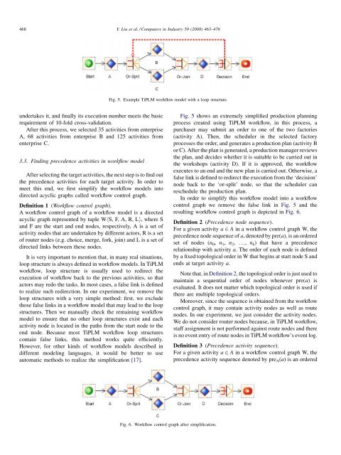
Fig. 5. Example TiPLM <strong>workflow</strong> model with a loop structure.<br />
undertakes it, and finally its execution number meets the basic<br />
requirement <strong>of</strong> 10-fold cross-validation.<br />
After this process, we selected 35 activities from enterprise<br />
A, 68 activities from enterprise B and 125 activities from<br />
enterprise C.<br />
3.3. Finding precedence activities in <strong>workflow</strong> model<br />
After selecting the target activities, the next step is to find out<br />
the precedence activities <strong>for</strong> each target activity. In order to<br />
meet this end, we first simplify the <strong>workflow</strong> models into<br />
directed acyclic graphs called <strong>workflow</strong> control graph.<br />
Definition 1 (Workflow control graph).<br />
A <strong>workflow</strong> control graph <strong>of</strong> a <strong>workflow</strong> model is a directed<br />
acyclic graph represented by tuple WhS, F, A, R, Li, where S<br />
and F are the start and end nodes, respectively, A is a set <strong>of</strong><br />
activity nodes that are undertaken by different actors, R is a set<br />
<strong>of</strong> router nodes (e.g. choice, merge, <strong>for</strong>k, join) and L is a set <strong>of</strong><br />
directed links between these nodes.<br />
It is very important to mention that, in many real situations,<br />
loop structure is always defined in <strong>workflow</strong> models. In TiPLM<br />
<strong>workflow</strong>, loop structure is usually used to redirect the<br />
execution <strong>of</strong> <strong>workflow</strong> back to the previous activities, so that<br />
actors may redo the tasks. In most cases, a false link is defined<br />
to realize such redirection. In our experiment, we remove the<br />
loop structures with a very simple method: first, we exclude<br />
those false links in a <strong>workflow</strong> model that may lead to the loop<br />
structures. Then we manually check the remaining <strong>workflow</strong><br />
model to ensure that no other loop structures exist and each<br />
activity node is located in the paths from the start node to the<br />
end node. Because most TiPLM <strong>workflow</strong> loop structures<br />
contain false links, this method works quite efficiently.<br />
However, <strong>for</strong> other kinds <strong>of</strong> <strong>workflow</strong> models described in<br />
different modeling languages, it would be better to use<br />
<strong>automatic</strong> methods to realize the simplification [17].<br />
Fig. 5 shows an extremely simplified production planning<br />
process created using TiPLM <strong>workflow</strong>, in this process, a<br />
purchaser may submit an order to one <strong>of</strong> the two factories<br />
(activity A). Then, the scheduler in the selected factory<br />
processes the order, and generates a production plan (activity B<br />
or C). After the plan is generated, a production manager reviews<br />
the plan, and decides whether it is suitable to be carried out in<br />
the workshops (activity D). If it is approved, the <strong>workflow</strong><br />
executes to an end and the new plan is carried out. Otherwise, a<br />
false link is defined to redirect the execution from the ‘decision’<br />
node back to the ‘or-split’ node, so that the scheduler can<br />
reschedule the production plan.<br />
In order to simplify this <strong>workflow</strong> model into a <strong>workflow</strong><br />
control graph we remove the false link in Fig. 5 and the<br />
resulting <strong>workflow</strong> control graph is depicted in Fig. 6.<br />
Definition 2 (Precedence node sequence).<br />
For a given activity a 2 A in a <strong>workflow</strong> control graph W, the<br />
precedence node sequence <strong>of</strong> a, denoted by pre(a), is an ordered<br />
set <strong>of</strong> nodes (n 0 , n 1 , n 2 , ..., n k ) that have a precedence<br />
relationship with activity a. The order <strong>of</strong> each node is defined<br />
by a fixed topological order in W that begins at start node S and<br />
ends at target activity a.<br />
Note that, in Definition 2, the topological order is just used to<br />
maintain a sequential order <strong>of</strong> nodes whenever pre(a) is<br />
evaluated. It does not matter which topological order is used if<br />
there are multiple topological orders.<br />
Moreover, since the sequence is obtained from the <strong>workflow</strong><br />
control graph, it may contain activity nodes as well as route<br />
nodes. In our experiment, we just consider the activity nodes.<br />
We do not consider router nodes because, in TiPLM <strong>workflow</strong>,<br />
<strong>staff</strong> <strong>assignment</strong> is not per<strong>for</strong>med against route nodes and there<br />
is no event entry <strong>of</strong> route nodes in TiPLM <strong>workflow</strong>’s event log.<br />
Definition 3 (Precedence activity sequence).<br />
For a given activity a 2 A in a <strong>workflow</strong> control graph W, the<br />
precedence activity sequence denoted by pre A (a) is an ordered<br />
Fig. 6. Workflow control graph after simplification.