representation of an induction motor in field-oriented steering ...
representation of an induction motor in field-oriented steering ...
representation of an induction motor in field-oriented steering ...

Create successful ePaper yourself
Turn your PDF publications into a flip-book with our unique Google optimized e-Paper software.
136<br />
J. Anuszczyk, M. Jabłoński<br />
4. THE INFLUENCE OF EQUIVALENT PARAMETERS<br />
OF THE MODEL ON THE PERFORMANCE<br />
OF THE STEERING ALGORITHM<br />
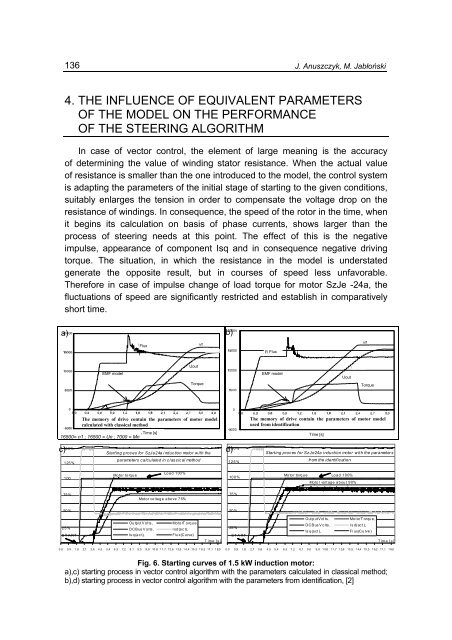
In case <strong>of</strong> vector control, the element <strong>of</strong> large me<strong>an</strong><strong>in</strong>g is the accuracy<br />
<strong>of</strong> determ<strong>in</strong><strong>in</strong>g the value <strong>of</strong> w<strong>in</strong>d<strong>in</strong>g stator resist<strong>an</strong>ce. When the actual value<br />
<strong>of</strong> resist<strong>an</strong>ce is smaller th<strong>an</strong> the one <strong>in</strong>troduced to the model, the control system<br />
is adapt<strong>in</strong>g the parameters <strong>of</strong> the <strong>in</strong>itial stage <strong>of</strong> start<strong>in</strong>g to the given conditions,<br />
suitably enlarges the tension <strong>in</strong> order to compensate the voltage drop on the<br />
resist<strong>an</strong>ce <strong>of</strong> w<strong>in</strong>d<strong>in</strong>gs. In consequence, the speed <strong>of</strong> the rotor <strong>in</strong> the time, when<br />
it beg<strong>in</strong>s its calculation on basis <strong>of</strong> phase currents, shows larger th<strong>an</strong> the<br />
process <strong>of</strong> steer<strong>in</strong>g needs at this po<strong>in</strong>t. The effect <strong>of</strong> this is the negative<br />
impulse, appear<strong>an</strong>ce <strong>of</strong> component Isq <strong>an</strong>d <strong>in</strong> consequence negative driv<strong>in</strong>g<br />
torque. The situation, <strong>in</strong> which the resist<strong>an</strong>ce <strong>in</strong> the model is understated<br />
generate the opposite result, but <strong>in</strong> courses <strong>of</strong> speed less unfavorable.<br />
Therefore <strong>in</strong> case <strong>of</strong> impulse ch<strong>an</strong>ge <strong>of</strong> load torque for <strong>motor</strong> SzJe -24a, the<br />
fluctuations <strong>of</strong> speed are signific<strong>an</strong>tly restricted <strong>an</strong>d establish <strong>in</strong> comparatively<br />
short time.<br />
a) b)<br />
Strumień Flux<br />
n/f<br />
Uwyj.<br />
Strumień Flux Flux<br />
n/f<br />
EMF model<br />
Uout<br />
Moment Torque<br />
EMF model<br />
Uwyj.<br />
Uout<br />
Torque<br />
Moment<br />
The memory <strong>of</strong> drive conta<strong>in</strong> the parameters <strong>of</strong> <strong>motor</strong> model<br />
calculated with classical method<br />
Time [s]<br />
16500= n1 ; 16500 = Un ; 7000 = Mn<br />
150%<br />
150%<br />
c) d)<br />
Start<strong>in</strong>g proces for SzJe24a <strong><strong>in</strong>duction</strong> <strong>motor</strong> with the<br />
parameters calculated <strong>in</strong> classical method<br />
125%<br />
125%<br />
The memory <strong>of</strong> drive conta<strong>in</strong> the parameters <strong>of</strong> <strong>motor</strong> model<br />
used from identification<br />
Time [s]<br />
Start<strong>in</strong>g proces for SzJe24a <strong><strong>in</strong>duction</strong> <strong>motor</strong> with the parameters<br />
from the identification<br />
100<br />
Mo tor to rq u e<br />
Load 100%<br />
10 0 %<br />
Motor torque<br />
Load 100%<br />
Motor voltage about 90%<br />
75 %<br />
Motor voltage above 75%<br />
75 %<br />
50 %<br />
50 %<br />
25%<br />
START<br />
OutputVol ts ,<br />
DCBusVolts,<br />
Isq(act),<br />
MotorTorque,<br />
Isd(act),<br />
Flux(Curve)<br />
Time [s]<br />
25 %<br />
START<br />
OutputVolts ,<br />
DCBusVolts,<br />
Isq(act),<br />
MotorTorque,<br />
Isd(act),<br />
Flux(Curve)<br />
Time [s]<br />
0,0 0,9 1,8 2,7 3,6 4,5 5,4 6,3 7,2 8,1 9,0 9,9 10,8 11,7 12,6 13,5 14,4 15,3 16,2 17,1 18,0<br />
0 ,0 0 ,9 1 ,8 2 ,7 3 ,6 4 ,5 5 ,4 6 ,3 7 ,2 8 ,1 9 ,0 9,9 1 0,8 11 ,7 1 2,6 13 ,5 1 4,4 15 ,3 1 6,2 17 ,1 1 8,0<br />
Fig. 6. Start<strong>in</strong>g curves <strong>of</strong> 1.5 kW <strong><strong>in</strong>duction</strong> <strong>motor</strong>:<br />
a),c) start<strong>in</strong>g process <strong>in</strong> vector control algorithm with the parameters calculated <strong>in</strong> classical method;<br />
b),d) start<strong>in</strong>g process <strong>in</strong> vector control algorithm with the parameters from identification, [2]