representation of an induction motor in field-oriented steering ...
representation of an induction motor in field-oriented steering ...
representation of an induction motor in field-oriented steering ...

You also want an ePaper? Increase the reach of your titles
YUMPU automatically turns print PDFs into web optimized ePapers that Google loves.
Representation <strong>of</strong> <strong>an</strong> <strong><strong>in</strong>duction</strong> <strong>motor</strong> <strong>in</strong> <strong>field</strong>-<strong>oriented</strong> steer<strong>in</strong>g algorithm ... 131<br />
Depend<strong>in</strong>g on the utilization <strong>of</strong> the exam<strong>in</strong>ed drive system there is access to the<br />
parameters adjust<strong>in</strong>g the dynamics <strong>of</strong> the supplied <strong><strong>in</strong>duction</strong> <strong>motor</strong> (these<br />
parameters are shown on the functional block diagrams <strong>of</strong> the <strong>in</strong>verter, [2], [3]).<br />
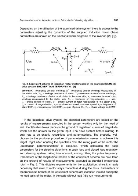
Fig. 2. Equivalent schema <strong>of</strong> <strong><strong>in</strong>duction</strong> <strong>motor</strong> implemented <strong>in</strong> the exam<strong>in</strong>ed SIEMENS<br />
drive system SIMOVERT MASTERDRIVES VC, [3]<br />
Where: R S – resist<strong>an</strong>ce <strong>of</strong> stator w<strong>in</strong>d<strong>in</strong>gs, R ’ r – resist<strong>an</strong>ce <strong>of</strong> rotor w<strong>in</strong>d<strong>in</strong>gs recalculated to<br />
the stator side, X Sσ – leakage react<strong>an</strong>ce <strong>of</strong> stator, X S – own react<strong>an</strong>ce <strong>of</strong> stator w<strong>in</strong>d<strong>in</strong>gs,<br />
X ’ rσ – leakage react<strong>an</strong>ce <strong>of</strong> rotor recalculated to the stator side, X ’ r – own react<strong>an</strong>ce <strong>of</strong> rotor<br />
w<strong>in</strong>d<strong>in</strong>gs recalculated to the stator side, X m – react<strong>an</strong>ce <strong>of</strong> magnetization, s – slip,<br />
I S – phase current <strong>of</strong> stator, I r ’ – phase current <strong>of</strong> rotor recalculated to the stator side,<br />
I m – current <strong>of</strong> magnetization, n 1 – synchronous speed, n – rotor speed, f 1 – frequency <strong>of</strong><br />
stator EMF, f 2 – frequency <strong>of</strong> rotor EMF, p – pair <strong>of</strong> poles, U ph , E ph – phase voltage <strong>an</strong>d EMF<br />
In the described drive system, the identified parameters are based on the<br />
results <strong>of</strong> measurements executed <strong>in</strong> the system work<strong>in</strong>g only for the need <strong>of</strong><br />
test. Identification takes place on the ground <strong>of</strong> registered curves <strong>of</strong> magnitude,<br />
which are the <strong>an</strong>swer to the given <strong>in</strong>put. The drive system before start<strong>in</strong>g its<br />
duty has to be exactly recognized <strong>an</strong>d parameterized. The properly, wellchosen<br />
by the producer procedure <strong>of</strong> parameterization serves to achieve this<br />
target. Right after <strong>in</strong>putt<strong>in</strong>g the qu<strong>an</strong>tities from the rat<strong>in</strong>g plate <strong>of</strong> the <strong>motor</strong> the<br />
„automation parameterization” is executed, which calculates the basic<br />
parameters for the steer<strong>in</strong>g algorithms <strong>in</strong> open loop <strong>an</strong>d closed loop regulation<br />
<strong>an</strong>d steer<strong>in</strong>g system, tak<strong>in</strong>g <strong>in</strong>to account, among other, the pulse frequency.<br />
Parameters <strong>of</strong> the longitud<strong>in</strong>al br<strong>an</strong>ch <strong>of</strong> the equivalent schema are calculated<br />
on the ground <strong>of</strong> results <strong>of</strong> measurements executed at st<strong>an</strong>dstill (motionless<br />
rotor) – Fig. 3. This dictates requirements for the exploitation, s<strong>in</strong>ce it is really<br />
necessary that rotor <strong>of</strong> <strong>motor</strong> stays motionless dur<strong>in</strong>g the tests. Parameters <strong>of</strong><br />
the tr<strong>an</strong>sverse br<strong>an</strong>ch <strong>of</strong> the equivalent schema are identified <strong>in</strong>stead dur<strong>in</strong>g the<br />
no-load tests <strong>of</strong> the <strong>motor</strong>, <strong>in</strong> the state without load (idle-run measurement).