Base coupled differential amplifier - Dipartimento di Ingegneria dell ...
Base coupled differential amplifier - Dipartimento di Ingegneria dell ...
Base coupled differential amplifier - Dipartimento di Ingegneria dell ...

Create successful ePaper yourself
Turn your PDF publications into a flip-book with our unique Google optimized e-Paper software.
INTERNATIONAL JOURNAL OF CIRCUIT THEORY AND APPLICATIONS<br />
Int. J. Circ. Theor. Appl. 2003; 31:351–360 (DOI: 10.1002/cta.237)<br />
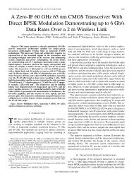
<strong>Base</strong> <strong>coupled</strong> <strong>di</strong>erential amplier: a new topology for RF<br />
integrated LNA<br />
S. Di Pascoli 1 , L. Fanucci 2; ∗; † , B. Neri 1 and D. Zito 1<br />
1 <strong>Dipartimento</strong> <strong>di</strong> <strong>Ingegneria</strong> <strong>dell</strong>’Informazione; Universita <strong>di</strong> Pisa; Via Diotisalvi 2; Pisa I-56122; Italy<br />
2 C. S. Meto<strong>di</strong> e Dispositivi per Ra<strong>di</strong>otrasmissioni; Consiglio Nazionale <strong>dell</strong>e Ricerche; Via Diotisalvi 2;<br />
Pisa I-56122; Italy<br />
SUMMARY<br />
A new topology of bipolar low noise amplier (LNA) for RF applications, named base <strong>coupled</strong> <strong><strong>di</strong>fferential</strong><br />
(BCD), is presented. The proposed approach is compared by simulation against most classical<br />
topologies. The BCD conguration has the key advantage to join an integrated matching on a singleended<br />
input with a <strong>di</strong>erential output. This is done by using down-bond wiring, so that no integrated<br />
inductors are needed. The main advantages of this new topology are a drastic area reduction and an<br />
increased linearity range (or a reduced biasing current with the same linearity) together with a noise<br />
gure (NF) and voltage supply reduction. Particularly, the BCD LNA presented in this paper has been<br />
designed for 2:44 GHz frequency operation. It is characterized by a NF of 1:93 dB, a voltage gain (Av)<br />
of 19:5 dB, an input impedance of 50 a third Input-referred Intercept Point (IIP 3 )of−7:25 dBm and<br />
a <strong>di</strong>ssipated power (P D ) equal to 19 mW. Copyright ? 2003 John Wiley & Sons, Ltd.<br />
KEY WORDS: low noise amplier (LNA); bipolar technology; ra<strong>di</strong>o frequency<br />
1. INTRODUCTION<br />
The rst stage of any integrated receiver for wireless applications is a low noise amplier<br />
(LNA). The design of this stage is very <strong>di</strong>cult since it has to be compliant with several<br />
specications. The most important are: the noise gure (NF), the input dynamic range, the<br />
matching of the input impedance to 50 and the <strong>di</strong>ssipated power. Moreover, a <strong>di</strong>erential<br />
topology to reduce the eects of common mode interferences is recommended for LNA in<br />
wireless applications. Typically, this choice has the drawback to require a balun transformer<br />
between the antenna and the input of the amplier and to determine an increase of the<br />
<strong>di</strong>ssipated power.<br />
∗ Correspondence to: Dr. L. Fanucci, C. S. Meto<strong>di</strong> e Dispositivi per Ra<strong>di</strong>otrasmissioni, Consiglio Nazionale <strong>dell</strong>e<br />
Ricerche, Via Diotisalvi 2, I-56122 Pisa, Italy.<br />
† E-mail: luca.fanucci@iet.unipi.it<br />
Contract=grant sponsor: National Research Council of Italy (CNR) in the framework of the nalized project<br />
‘Materiali e Dispositivi per l’Elettronica a Stato Solido’ (MADESS II)<br />
Received 14 January 2002<br />
Copyright ? 2003 John Wiley & Sons, Ltd. Revised 3 September 2002
352 S. DI PASCOLI ET AL.<br />
Figure 1. Input matching technique.<br />
Another target of the LNA design is the so-called integrated matching, which means to<br />
simultaneously match the minimum NF and the maximum power with Z in =Z ON =50 , being<br />
Z in the input impedance and Z ON the optimum source impedance for the NF [1]. It has been<br />
demonstrated that this result can be achieved in integrated form by suitably choosing the<br />
transistor quiescent point and by using two inductors as shown in Figure 1.<br />
By proper <strong>di</strong>mensioning L 0 and L 1 and by choosing a suitable value for the biasing current<br />
I C and the area size of the input transistor, the integrated matching can be obtained [1,2]. It<br />
is well known that the utilization of integrated inductors causes some problems mainly due<br />
to the quite low value of their quality factor Q (typically Q is lower than 10) and to the<br />
large area occupied on <strong>di</strong>e. Particularly, the low Q implies a not negligible series equivalent<br />
resistance, which impairs the NF, and the large area has a negative impact on yield and cost.<br />
For this reason, whenever it is possible, inductors are realized by exploiting wire bon<strong>di</strong>ng<br />
[3]. Unfortunately, this solution can be adopted only when the inductor is connected in series<br />
with an external lead or with the back grounded plane.<br />
In the past, several LNA topologies have been proposed, but the most widely utilized are<br />
the common emitter, with an emitter degeneration, and the cascode congurations [4].<br />
Taking into account all the above considerations, in Section 2, we propose a new topology of<br />
bipolar LNA named base <strong>coupled</strong> <strong>di</strong>erential (BCD). This approach allows a reduction of the<br />
<strong>di</strong>e area and an increase of the dynamic range without causing any performance degradation<br />
in terms of NF, <strong>di</strong>ssipated power and gain. A comparison among the BCD topology and the<br />
most common ones has been carried out and the results of the simulations are summarized<br />
in Section 3. In Section 4 these results are <strong>di</strong>scussed and nally some conclusions are drawn<br />
in Section 5.<br />
2. BASE COUPLED DIFFERENTIAL AMPLIFIER<br />
The proposed BCD amplier is shown in Figure 2, where some details are omitted for sake<br />
of clarity. Particularly, I B represents a DC current source implemented by a current mirror<br />
scheme. L 1 is realized by means of down-bon<strong>di</strong>ng wire to the ground plane and L 0 is obtained<br />
by using bon<strong>di</strong>ng wire to the input pad: both of them are necessary to obtain the<br />
Copyright ? 2003 John Wiley & Sons, Ltd. Int. J. Circ. Theor. Appl. 2003; 31:351–360
BASE COUPLED DIFFERENTIAL AMPLIFIER 353<br />
Figure 2. <strong>Base</strong> <strong>coupled</strong> <strong>di</strong>erential (BCD) amplier.<br />
integrated input matching. The Q values for the wire bon<strong>di</strong>ng inductors have been estimated<br />
in 30.<br />
If C 0 is not considered, the scheme recalls two cascode stages connected back to back each<br />
other through the bases of transistors Q 2 and Q 4 . For small signals, i b2 = −i b4 , where i b2 and i b4<br />
are the base current small signal variations of Q 2 and Q 4 , respectively. At low frequencies, at<br />
which the eects of the intrinsic capacitances of the transistors are negligible, i b2 =i e2 =(h fe2 +1)<br />
and i b4 =i e4 =(h fe4 + 1). Here, i e2 and i e4 are the small signal variations of the emitter current<br />
while h fe2 and h fe4 are the current gain, of Q 2 and Q 4 , respectively. In the ideal case h fe2 =h fe4 ,<br />
then the variations of the emitter currents of the two transistors and, consequently, those of<br />
the respective collector currents, have the same magnitude, but opposite sign. Therefore, a<br />
perfectly symmetric output is obtained and the amplier realizes the aforementioned transition<br />
from a single-ended input to a <strong>di</strong>erential output, in an ideal way.<br />
This solution combines three undeniable positive aspects for LNA design: (i) maximum<br />
linear operating range accor<strong>di</strong>ng to Reference [5], also conrmed by the simulation results<br />
reported in Section 3; (ii) high common mode interference rejection due to the <strong>di</strong>erential<br />
conguration scheme; (iii) reduced silicon area and noise since high quality factor (Q¿30)<br />
inductors, realized by means of wire bon<strong>di</strong>ng, are used instead of integrated inductors.<br />
The operating point is the same for Q 2 and Q 4 . The shunt capacitor C 0 has been introduced<br />
to reduce the input impedance seen from the base of Q 4 . At high frequencies,<br />
its eect is very important to obtain the opposite values of Q 2 and Q 4 collector currents.<br />
SpectreRF TM simulation results have shown that a slight unbalancing of the output voltages<br />
can be completely recovered by ad<strong>di</strong>ng a very low value capacitance (tens of fF, not shown in<br />
Copyright ? 2003 John Wiley & Sons, Ltd. Int. J. Circ. Theor. Appl. 2003; 31:351–360
354 S. DI PASCOLI ET AL.<br />
Figure 3. BCD output voltages: (a) magnitude and (b) phase.<br />
Figure 2) between the collector and the base of Q 2 . The Figure 3 shows the output voltages<br />
of the BCD stage (V out+ and V out− signals), both in magnitude and in phase, for the frequency<br />
range of interest and for 1 mV of input signal. The symmetry of the two output with respect<br />
to ground, around 2:44 GHz, is remarkable.<br />
3. DIFFERENT TOPOLOGIES: SIMULATION RESULTS<br />
The comparison has been carried out among <strong>di</strong>erent topologies characterized by a singleended<br />
input signal, so that no balun is required.<br />
In that respect, one of the most widely used congurations for low cost wireless applications<br />
is the <strong>di</strong>erential cascode, named emitter <strong>coupled</strong> <strong>di</strong>erential (ECD), shown in Figure 4.<br />
The inductors (L 0 ; L 1 and L 2 ) realize the integrated matching. The considered L 0 can be<br />
implemented by a bon<strong>di</strong>ng wire plus a microstrip while L 1 and L 2 have to be integrated<br />
on chip. The parasitic series resistance of L 0 has been calculated by considering a quality<br />
factor Q nearly equal to 30. The on-chip inductors, L 1 and L 2 , have been calculated by<br />
considering Q=8. They are characterized by an area size of about 100 m×100 m each.<br />
The main advantage of this solution is the bandwidth and the immunity to the common mode<br />
interferences, on the contrary, the main drawback is the impossibility to exploit the downbon<strong>di</strong>ng<br />
to implement L 1 and L 2 for the integrated matching. This is due to the fact that the<br />
emitters of Q 1 and Q 2 have to be connected to the internal current source. Another negative<br />
Copyright ? 2003 John Wiley & Sons, Ltd. Int. J. Circ. Theor. Appl. 2003; 31:351–360
BASE COUPLED DIFFERENTIAL AMPLIFIER 355<br />
Figure 4. Emitter <strong>coupled</strong> <strong>di</strong>erential (ECD) amplier.<br />
aspect is the reduced linearity, if compared with a single-ended cascode amplier (as the<br />
BCD). In fact, Meyer has demonstrated in Reference [5] that, at a xed <strong>di</strong>ssipated power,<br />
the <strong>di</strong>erential pair transconductance stage exhibits an IIP3 about twice lower than that of the<br />
common emitter stage.<br />
The comparison has been also extended to the circuit conguration shown in Figure 5,<br />
named double stage <strong>di</strong>erential (DSD), where the <strong>di</strong>erential amplier follows a single-ended<br />
cascode, in order to obtain a <strong>di</strong>erential output. In this case, down-bon<strong>di</strong>ng wire can be<br />
exploited to realize the input integrated matching.<br />
For each conguration the design has been carried out to obtain the best tradeo between<br />
power consumption, noise gure and area size; obviously, the values of the DC current I B<br />
and I 0 are <strong>di</strong>erent for each case.<br />
As seen in Section 1, many parameters are normally used to summarize the LNA performances.<br />
For a reasonable comparative analysis among the <strong>di</strong>erent schemes, the choice has<br />
been done to keep constant some of them. Because the most signicant parameters of a LNA<br />
are the NF and the gain at 50 of source impedance, the biasing point has been chosen in<br />
such a way to obtain the same NF (which, in this case, is very close to the minimum NF of<br />
the transistors) so, in all the cases, the integrated matching has been realized. Moreover, gain<br />
and output impedance are the same for all congurations.<br />
The ampliers have been designed by using the HSB3 (high speed bipolar) bipolar process<br />
by ST microelectronics. It is a polysilicon self-aligned process (with three levels of metals) for<br />
Copyright ? 2003 John Wiley & Sons, Ltd. Int. J. Circ. Theor. Appl. 2003; 31:351–360
356 S. DI PASCOLI ET AL.<br />
Figure 5. Double stage <strong>di</strong>erential (DSD) amplier.<br />
Table I. Simulation results; A v is the forward voltage gain (V out =V in ); IS is the reverse<br />
voltage gain (V in =V out ) evaluated at 2:54 GHz; PSRR is the ratio A v=A CC , where A CC<br />
is V out =V CC at 2:54 GHz.<br />
BCD ECD DSD<br />
NF (dB) @ 2:44 GHz 1.93 2.50 2.23<br />
A v (dB) @ 2:44 GHz 19.5 19.5 19.5<br />
Z in ()@2:44 GHz 50 50 50<br />
P D (mW) 19 21.3 25.8<br />
IIP 3 (dBm) −7:25 −8:8 −13:3<br />
IS (dB) @ 2:54 GHz −53:9 −54:9 −70:1<br />
PSRR (dB) @ 2:44 GHz 21.55 10.97 19.16<br />
Area (mm 2 ) 0.027 0.077 —<br />
Down-bon<strong>di</strong>ng Yes No yes<br />
RF application, with 50 GHz of cut-o frequency. The transistors used have up to three base<br />
contacts in order to reduce the intrinsic resistance, and so, to oer the best noise performances.<br />
The quality factor values of the inductors taken into account here are typically obtainable at<br />
the considered operating frequency (2.44 GHz) and they have been suggested from practice.<br />
The simulations results have been performed by means of SpectreRF TM , a commercial RF<br />
analog circuit simulator integrated within the Cadence TM design framework. Perio<strong>di</strong>c steadystate<br />
analysis has been utilized to pre<strong>di</strong>ct the third intercept point (IP 3 ) and the 1 dB compression<br />
point (CP 1dB ). The best results obtained for each conguration are reported in<br />
Table I and <strong>di</strong>scussed in Section 4. The IIP 3 has been evaluated considering two input<br />
tones at frequencies f 1 =2:432 GHz and f 2 =2:448 GHz. The 1 dB input compression point<br />
Copyright ? 2003 John Wiley & Sons, Ltd. Int. J. Circ. Theor. Appl. 2003; 31:351–360
BASE COUPLED DIFFERENTIAL AMPLIFIER 357<br />
Figure 6. (a) BCD layout: total area (double trench included)=404×1260m 2 ; h a =125m,<br />
w a =215 m; (b) ECD layout: total area =574×1430 m 2 ; h b =205 m, w b =375 m.<br />
(ICP 1dB ) is approximately 9:6 dB lower than IIP 3 for all the considered congurations, so that<br />
it has not been reported in Table I. The load impedance has been considered equal to 1 KHz,<br />
which is nearly the input impedance presented by the following buer stage.<br />
Figure 6 shows the layouts of the BCD and the ECD ampliers (a) and (b), respectively. In<br />
both of them, BP is the ground shielded pad connected to the base of the input transistor Q1;<br />
in Figure 6(a) EP is the ground shielded pad connected to the emitter of the input transistor<br />
Q1 which has to be down-bon<strong>di</strong>ng wired to the back grounded plane.<br />
Clearly, the area required by the ECD is larger mainly due to the integrated inductors.<br />
The layout of the DSD amplier is not shown because it is characterized by the same area<br />
complexity as the BCD since it does not require any on-chip inductors.<br />
To obtain an exact comparison in terms of area, the same <strong>di</strong>stance between input and<br />
output terminals has been preserved. In the area size (h×w product) reported in Table I, the<br />
area contributions of the capacitor C 0 and of the output buer stage have not been taken into<br />
account considering only the contribution of the amplier itself. It is worth noting that the DC<br />
current source I B of the BCD amplier is generated by means of a proportional to absolute<br />
temperature (PTAT) cell which requires a larger area than a simple current mirror.<br />
Copyright ? 2003 John Wiley & Sons, Ltd. Int. J. Circ. Theor. Appl. 2003; 31:351–360
358 S. DI PASCOLI ET AL.<br />
4. COMPARISONS AND DISCUSSION<br />
The main parameters in Table I, which have been considered for the comparison, are: the<br />
<strong>di</strong>ssipated power P D , the IIP 3 , the area size and the minimum value required for the power<br />
supply V CC . As far as P D is concerned, it is worth noting that, in both ECD and DSD<br />
conguration, the total current is greater that I 0 . Indeed, in Figures 4 and 5 the current mirror<br />
realizing the current source is not represented. The current I 0 has been obtained by using a<br />
current mirror realized by means of two transistors whose area ratio is 1 6<br />
, so that, in this way,<br />
the total current supplied by the batteries is I 0 + I 0 =6.<br />
Other parameters to be considered are isolation (IS) and power supply rejection ratio<br />
(PSRR). The former is dened as the ratio V in =V out (measured by supplying the output with a<br />
small signal and by shunting the input with a 50 resistor), which gives a measurement of the<br />
possible eects of the local oscillator to the input (oscillation frequency has been considered<br />
equal to 2:54 GHz). PSRR is A v =A CC , where A CC is the ratio between the output voltage (V out )<br />
and a possible <strong>di</strong>sturb superimposed to the power supply.<br />
The rst comparison is carried out between BCD and DSD congurations since they are<br />
characterized by the same area complexity. In fact, both of them do not require any integrated<br />
inductor. The superior performances of the BCD are apparent for all the considered parameters,<br />
with the exception of the IS. The main advantage of BCD is the higher value of IIP 3 , whereas<br />
the main drawback of DSD is the <strong>di</strong>ssipated power which is larger by a factor of about 35%.<br />
The reduced value of IIP 3 for the DSD is due to the fact that the path between input and<br />
output is made up by a larger number of active devices (two for BCD and three for DSD).<br />
In the attempt to improve the IIP 3 for the DSD, a mo<strong>di</strong>ed conguration has been considered<br />
where the input cascode stage is replaced by a CE stage (as shown in Figure 7): the simulation<br />
Figure 7. Double stage <strong>di</strong>erential (DSD) amplier with common emitter as rst stage.<br />
Copyright ? 2003 John Wiley & Sons, Ltd. Int. J. Circ. Theor. Appl. 2003; 31:351–360
BASE COUPLED DIFFERENTIAL AMPLIFIER 359<br />
results showed a slight increase of IIP 3 at the expenses of a degradation of the isolation by<br />
a factor of about 20. For this reason this solution has not been reported in Table I.<br />
The second comparison is carried out between BCD and ECD congurations. The superiority<br />
of the BCD is quite evident also in this case, even if the ECD performances are better<br />
than those of the DSD. Particularly, two are the main advantages of the BCD: (i) the smaller<br />
area size and (ii) the smaller input-referred third-order intermodulation <strong>di</strong>stortion. The former<br />
advantage (i) does not require any further clarication: a comparison among the layouts reported<br />
in Figure 6 clearly show the negative impact on the area occupancy of the integrated<br />
inductors: the product w ×h is nearly 3 times larger than the one of the BCD solution. The<br />
latter advantage (ii) derives from the single-ended input which permits to obtain a larger<br />
linearity range, accor<strong>di</strong>ng to Meyer’s demonstration [5]. This is clearly validated by the data<br />
reported in Table I showing that BCD is characterized by the highest value of IIP 3 .<br />
5. CONCLUSIONS<br />
In this paper, we have presented the BCD as bipolar amplier topology which allows an<br />
integrated matching on a single-ended input with a <strong>di</strong>erential output. No integrated inductors<br />
are needed but down-bon<strong>di</strong>ng wire are used to realize the emitter inductive degeneration. The<br />
symmetry of the output voltages with respect to ground has been demonstrated and it has been<br />
conrmed by simulation results. The quasi-ideal <strong>di</strong>erential behaviour has been conrmed also<br />
taking into account the parasitic eects of physical layout, for the HSB3 bipolar technology<br />
by ST Microelectronics, and packaging. This scheme has been employed to realize a LNA in<br />
a2:44 GHz RF front-end for wireless local area network (WLAN) applications. The chip has<br />
been packaged in a TQFP 48 with exposed pad.<br />
A detailed comparative analysis with widely used tra<strong>di</strong>tional congurations, namely emitter<br />
<strong>coupled</strong> <strong>di</strong>erential (ECD) and double stage <strong>di</strong>erential (DSD), has been performed. With<br />
respect to the DSD solution, BCD shows a larger linearity range and a lower power consumption.<br />
With respect to ECD, BCD shows a higher linearity range (or a lower power<br />
consumption with the same linearity), an area complexity approximately three times smaller,<br />
a better noise gure and power supply rejection ratio.<br />
Finally, it is worth mentioning that BCD overall performances are among the best reported<br />
in References [6–8] in the last years in bipolar technology, particularly as far as NF is<br />
concerned.<br />
ACKNOWLEDGEMENTS<br />
This work has been supported by the National Research Council of Italy (CNR) in the framework of<br />
the Finalized Project “Materiali e Dispositivi per l’Elettronica a Stato Solido” (MADESS II).<br />
REFERENCES<br />
1. Palmisano G, Girlando G. Noise gure and input matching in RF cascode ampliers. IEEE Transactions on<br />
Circuits and Systems II: Analog and Digital Signal Processing 1999; 46:1388–1396.<br />
2. Voinigescu SP, Maliepaard MC, Showell JL, Babcock GE, Marchesan D, Schroter M, Schvan P, Harame D. A<br />
scalable high-frequency noise model for bipolar transistors with applications to optimal transistors sizing for low<br />
noise amplier design. IEEE Journal of Solid-State Circuits 1999; 46:1388–1396.<br />
Copyright ? 2003 John Wiley & Sons, Ltd. Int. J. Circ. Theor. Appl. 2003; 31:351–360
360 S. DI PASCOLI ET AL.<br />
3. Colvin JT, Bhatia SS, O KK. Eects of the substrate resistances on LNA performance and a bondpad structure<br />
for reducing the eects in a silicon bipolar technology. IEEE Journal of Solid-State Circuits 1999; 34:<br />
1339–1344.<br />
4. Baringer C, Hull C. Ampliers for wireless communications. In Microwave and RF Circuits Design for Wireless<br />
Communications, Larson LE (ed.), Artech House: Norwood, MA, USA 1997; 345–382.<br />
5. Fong KL, Meyer RG. High-frequency nonlinearity analysis of common-emitter and <strong>di</strong>erential-pair<br />
transconductance stages. IEEE Journal of the Solid-State Circuits 1998; 33:548–555.<br />
6. Wuen W-S, Liu S-F, Chen K-Y, Wen K-A. Receiver front-end chipsets for 2.4-GHz wireless LAN in 0:5 m<br />
BiCMOS. Digest of Technical Papers Asia Pacic Microwave Conference 1999; 2:460–463.<br />
7. Komurasaki H, Sato H, Ono M, Ebana T, Takeda H, Takahashi K, Hayashi Y, Iga T, Hasegawa K, Miki<br />
T. A single-chip 2.4-GHz RF transceiver LSI with a wide-range FV conversion. Digest of Technical Papers<br />
Solid-State Circuits International Conference, 2001; 206–208.<br />
8. A<strong>di</strong>seno, Ismail M, Olson HK. In<strong>di</strong>rect negative feedback bipolar. Procee<strong>di</strong>ngs of Electronics, Circuits and<br />
Systems 1999 International Conference 1999; 1:509–512.<br />
Copyright ? 2003 John Wiley & Sons, Ltd. Int. J. Circ. Theor. Appl. 2003; 31:351–360