Update of ITER ISS-WDS Process Design - IFA
Update of ITER ISS-WDS Process Design - IFA
Update of ITER ISS-WDS Process Design - IFA

You also want an ePaper? Increase the reach of your titles
YUMPU automatically turns print PDFs into web optimized ePapers that Google loves.
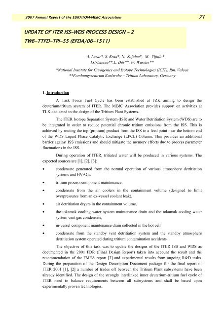
2007 Annual Report <strong>of</strong> the EURATOM-MEdC Association 71<br />
UPDATE OF <strong>ITER</strong> <strong>ISS</strong>-<strong>WDS</strong> PROCESS DESIGN – 2<br />
TW6-TTFD-TPI-55 (EFDA/06-1511)<br />
A. Lazar*, S. Brad*, N. S<strong>of</strong>alca*, M. Vijulie*<br />
I.Cristescu**,L. Dör**, W. Wurster**<br />
*National Institute for Cryogenics and Isotope Technologies (ICIT), Rm. Valcea<br />
**Forshungszentrum Karlsruhe – Tritium Laboratory, Germany<br />
1. Introduction<br />
A Task Force Fuel Cycle has been established at FZK aiming to design the<br />
deuterium/tritium system <strong>of</strong> <strong>ITER</strong>. The MEdC Association provides support on activities at<br />
TLK dedicated to the design <strong>of</strong> the Tritium Plant Systems.<br />
The <strong>ITER</strong> Isotope Separation System (<strong>ISS</strong>) and Water Detritiation System (<strong>WDS</strong>) are to<br />
be integrated in order to reduce potential chronic tritium emissions from the <strong>ISS</strong>. This is<br />
achieved by routing the top (protium) product from the <strong>ISS</strong> to a feed point near the bottom end<br />
<strong>of</strong> the <strong>WDS</strong> Liquid Phase Catalytic Exchange (LPCE) Column. This provides an additional<br />
barrier against <strong>ISS</strong> emissions and should mitigate the memory effects due to process parameter<br />
fluctuations in the <strong>ISS</strong>.<br />
During operation <strong>of</strong> <strong>ITER</strong>, tritiated water will be produced in various systems. The<br />
expected sources are [1], [2], [3]:<br />
• condensate generated from the normal operation <strong>of</strong> various atmosphere detritiation<br />
systems and HVACs.<br />
• tritium process component maintenance,<br />
• condensate from the air coolers in the containment volume (designed to limit<br />
overpressures from an ex-vessel coolant leak),<br />
• air detritiation dryers in the containment volume,<br />
• the tokamak cooling water system maintenance drain and the tokamak cooling water<br />
system vent gas condensate,<br />
• in-vessel component maintenance drain collected in the hot cell<br />
• condensate from the standby vent detritiation system and the standby atmosphere<br />
detritiation system operated during tritium contamination accidents.<br />
The objective <strong>of</strong> this task was to update the designs <strong>of</strong> the <strong>ITER</strong> <strong>ISS</strong> and <strong>WDS</strong> as<br />
documented in the 2001 FDR (Final <strong>Design</strong> Report) taken into account the result and the<br />
recommendation <strong>of</strong> the FMEA report [3] and experimental results from ongoing R&D tasks.<br />
During the preparation <strong>of</strong> the <strong>Design</strong> Description Document package for the final report <strong>of</strong><br />
<strong>ITER</strong> 2001 [1], [2] a number <strong>of</strong> trades <strong>of</strong>f between the Tritium Plant subsystems have been<br />
already identified. The design <strong>of</strong> the strongly interlinked inner deuterium-tritium fuel cycle <strong>of</strong><br />
<strong>ITER</strong> need to balance requirements between all subsystems and shall be based upon<br />
experimentally proven technologies.
72 Atentie<br />
2007 Annual Report <strong>of</strong> the EURATOM-MEdC Association<br />
The CATIA V5 s<strong>of</strong>tware was chosen to create, using the PRM (Project Resource<br />
Management) [8], the 3D layouts <strong>of</strong> plant sites by defining the buildings, the major areas, all the<br />
way down in the plant area, the path to the equipment and so on. Subareas for facilities and<br />
technological equipments have been created within the plant. The system allows a hierarchical<br />
approach including true partition <strong>of</strong> space with shared boundaries, areas with multi patches, and<br />
so on.<br />
2. <strong>Process</strong> Description<br />
The Combined Electrolysis Catalytic Exchange (CECE) method in combination with<br />
Cryogenic Distillation (CD) was chosen for tritium recovery from tritiated water which will be<br />
produced during <strong>ITER</strong> operation. A potential combination <strong>of</strong> the <strong>ITER</strong> <strong>WDS</strong> and <strong>of</strong> the <strong>ITER</strong><br />
<strong>ISS</strong> is shown in Figure 1.<br />
Figure 1. Block diagram <strong>of</strong> <strong>ISS</strong>-<strong>WDS</strong><br />
The <strong>ITER</strong> water detritiation plant comprises two subsystems to process and temporary<br />
store the quantities <strong>of</strong> tritiated water: the water detritiation system (<strong>WDS</strong>) and the tritiated water<br />
holding tank system [2]. The tritiated water holding tank system stores the various tritiated<br />
water streams according to the tritium concentrations prior to processing. Tritiated water is fed<br />
into the LPCE column at heights given by the tritium concentration. At the top <strong>of</strong> LPCE column<br />
natural water is added. Enriched tritiated water is collected in the column boiler from where is<br />
sent through a purification unit to the electrolyzer unit. An advanced electrolyzer based on solid<br />
polymer electrodes (SPE) was proposed for the <strong>ITER</strong> <strong>WDS</strong> to avoid the production <strong>of</strong> a mixed<br />
liquid waste containing high-level tritium concentration (mixture <strong>of</strong> tritiated water and alkaline<br />
solution). The electrolyzer decomposes tritium-enriched water into the tritium-rich H2 gas and<br />
O2 gas streams. The mixture is sent to a moister separator and to a membrane permeator for<br />
chemical purification and the purified permeate is fed into the <strong>ISS</strong> column 1 (CD1). The O2 gas<br />
stream, which contains a small fraction <strong>of</strong> HT gas and tritiated moisture (HTO), is sent for<br />
purification to the Oxygen Striping Column. Tritiated water with high tritium concentration will<br />
be primarily processed within a VPCE column.
2007 Annual Report <strong>of</strong> the EURATOM-MEdC Association 73<br />
Part <strong>of</strong> the tritium-rich H 2 gas stream is sent to the hydrogen isotope separation system<br />
(<strong>ISS</strong>) for tritium recovery, and the rest <strong>of</strong> tritium-rich H 2 gas stream is fed to the catalytic<br />
isotope exchange tower. The <strong>ISS</strong> utilizes cryogenic distillation to separate hydrogen isotope<br />
mixtures [1]. The <strong>ISS</strong> <strong>of</strong> <strong>ITER</strong> is considered to be the major source for stack releases and in this<br />
case it will be in the elemental form (HT). The <strong>ITER</strong> <strong>ISS</strong> columns consist <strong>of</strong> four distillation<br />
columns (CD1, CD2, CD3 and CD4). The four cryogenic distillation columns are directly<br />
connected and equilibrators (Eq) are employed to split the mixed hydrogen isotopes into H 2 , D 2<br />
and T 2 , respectively.<br />
Thereby the <strong>WDS</strong> is employed for detritiation and the <strong>ISS</strong> is employed for tritium<br />
recovery.<br />
3. Plant Layout <strong>Design</strong><br />
A 3D layout <strong>of</strong> the <strong>WDS</strong> and <strong>ISS</strong> systems in the building has been developed based on<br />
the FDR 2001 report and the recommendation from the reports presented at Tritium Plant<br />
Project Team (TPPT) Meeting Cadarache, 8-10 October 2007 [4],[5]. Figure 2 shows vertical<br />
views <strong>of</strong> the major equipment <strong>of</strong> the <strong>ISS</strong> and <strong>WDS</strong> within the building.<br />
Equipment <strong>ISS</strong><br />
<strong>WDS</strong>-<strong>ISS</strong> section <strong>of</strong><br />
TP building<br />
Equipment <strong>WDS</strong><br />
Equipment arrangement in the<br />
TP building<br />
Figure 2. <strong>WDS</strong>-<strong>ISS</strong> section <strong>of</strong> Tritium Plant Building<br />
The designing work involved spaces reservation for the major equipment <strong>of</strong> <strong>ITER</strong> <strong>ISS</strong>-<br />
<strong>WDS</strong> system, analysis <strong>of</strong> the area/volume allocations and optimization <strong>of</strong> the general 3D layout<br />
<strong>of</strong> plants and equipment. The arrangement <strong>of</strong> the constituent process systems has been<br />
optimized in terms <strong>of</strong> minimizing the length <strong>of</strong> interconnections, and has taken into account<br />
provision <strong>of</strong> adequate space for operation and maintenance, separation <strong>of</strong> the building areas into<br />
zones. The 3D layouts are organized in structures called product tree (skeleton) comprising<br />
assemblies, sub-assemblies and parts [8].<br />
Numbering, naming and symbols <strong>of</strong> components and equipment were chosen according<br />
to: <strong>ITER</strong>-FEAT Tritium Plant Numbering System (Doc. No. 32 OD 0010) [6],
74 Atentie<br />
2007 Annual Report <strong>of</strong> the EURATOM-MEdC Association<br />
<strong>ITER</strong>_Plant_Identifica_<strong>ITER</strong>_D_27KSGF_v10 [7], CATIA_V5_E&S_<strong>ITER</strong>_D_25DD33_v1.0<br />
[8].<br />
The equipment placement into the <strong>WDS</strong>-<strong>ISS</strong> layout was done taking into consideration<br />
the building constraints [6], [5]:<br />
<strong>WDS</strong> system:<br />
• B2 (basement level 2) - emergency tanks, L level holding tanks, LL level holding tanks,<br />
H level holding, <strong>WDS</strong> process drain tank.<br />
• B1 (basement level 1) - Tritium monitors for tritiated water, 2 electrolyzer, 2 electrical<br />
cabinet-electrolyzer, space reservation for piping connections.<br />
• L1 (Level 1) – 6 electrolyzer, 6 electrical cabinet-electrolyzer, space reservation for<br />
collecting vessels.<br />
• L2 (Level 2) - space reservation for LPCE columns & O2 stripping column, Space<br />
reservation for VPCE column.<br />
• L3 (level 3) - space reservation for LPCE columns & O2 stripping column, Electrical<br />
cabinet for CECE process, hydrogen purification unit.<br />
• L4 (level 4) - space reservation for LPCE columns & O2 stripping column, heating and<br />
cooling systems for LPCE columns, H 2 discharge.<br />
<strong>ISS</strong> system:<br />
• L2 (level 2) - helium buffer tank, H2 expansion tank, space for temporary storage <strong>of</strong><br />
lower CD cold-box, helium purification unit, helium compressor.<br />
• L3 (level 3) - CD lower cold-box, refrigeration unit, H2 expansion tank, helium<br />
purification & gas impurity measurement.<br />
• L4 (level 4) - CD cold-box, <strong>ISS</strong> Hard shell confinement, Vacuum system, Electrical<br />
cabinet for CD system, H 2 discharge.<br />
From the 3D <strong>WDS</strong> and <strong>ISS</strong> layouts, plot plans were generated with equipment<br />
arrangement for each floor. The plot plans has be send for review to the EFDA CSU Garching<br />
/<strong>ITER</strong>.<br />
4. Collaborative work<br />
Work related to these topics belongs to the task TW6-TTFD-TPI- 55-2 (Art.5.1b) from<br />
the EFDA Technology Work program 2006 and was done in collaboration with FZK<br />
Association team during the period January 2007 - December 2007.<br />
Part <strong>of</strong> this work has been performed during the two-month Mobility Secondment <strong>of</strong> A.<br />
Lazar at Forshungszentrum Karlsruhe – Tritium Laboratory, Germany.<br />
5. Conclusions<br />
Development <strong>of</strong> a Water Detritiation System (<strong>WDS</strong>) and an Isotope Separation System<br />
(<strong>ISS</strong>), configuration and design <strong>of</strong> critical components are essential for <strong>ITER</strong>. <strong>ITER</strong> needs the<br />
<strong>WDS</strong>&<strong>ISS</strong> systems to process tritiated water, which was accumulated from operation and also<br />
the tritiated water which will be generated during decommissioning. The <strong>WDS</strong> is based on the<br />
Combined Electrolysis Catalytic Exchange (CECE) process and is envisaged to work in
2007 Annual Report <strong>of</strong> the EURATOM-MEdC Association 75<br />
combination with the <strong>ISS</strong> with the aim to recover tritium contained in the processed tritiated<br />
water.<br />
The Block diagrams were developed in the Piping and Instrumentation Diagram<br />
application from the CATIA V5 s<strong>of</strong>tware, having as reference the process diagrams from the<br />
DDD _32_E report [2], DDD_32_B report [1] and FMEA report [3].<br />
A 3D layout <strong>of</strong> the <strong>WDS</strong> and <strong>ISS</strong> systems arrangement into the building has been<br />
developed and plot plans were generated with equipment arrangement for each floor. The plot<br />
plans have been sent for review to the EFDA CSU Garching / <strong>ITER</strong>.<br />
The <strong>ITER</strong> inputs will be used in a near future for the process design update <strong>of</strong> the<br />
<strong>WDS</strong>-<strong>ISS</strong> systems, if required.<br />
References<br />
[1] Kveton O. K., “Tritium Plant and Detritiation Systems - Hydrogen Isotope Separation<br />
System (WBS 3.2B)”.<br />
[2] Yoshida H., “Tritium Plant and Detritiation Systems Water Detritiation System and<br />
Tritiated Water Holding Tank System (WBS 3.2.E)”.<br />
[3] Rizzello C., Pinna T., “Failure Mode and Effect Analysis for Water Detritiation System <strong>of</strong><br />
<strong>ITER</strong>”.<br />
[4] Cristescu I., “<strong>WDS</strong>-<strong>ISS</strong> space allocation”, presented at Tritium Plant Project Team (TPPT)<br />
Meeting Cadarache, 8-10 October 2007.<br />
[5] Beloglazov S., “TP_Layout_<strong>ITER</strong>_D_28YUVW_v1.0[1]”, presented at Tritium Plant<br />
Project Team (TPPT) Meeting Cadarache, 8-10 October 2007.<br />
[6] Gugla M., Yoshida H., “<strong>ITER</strong>-FEAT Tritium Plant Numbering System (Doc. No. 32 OD<br />
0010)”<br />
[7] Belogazov S., Chiocchio S.,“<strong>ITER</strong>_Plant_Identifica_<strong>ITER</strong>_D_27KSGF_v1_0”<br />
[8] Belogazov S., Caldwell C., Glugla M., Lazar A., Lux M., Wagner R., Weber V.,“PRM<br />
and Standard Parts Catalogues in CATIA V5 for Tritium containing Systems and Components”<br />
[9] Standards,“EN ISO 10628”, “EN ISO 3511”, “DIN 28401”, “ASME section VIII, div.1 –<br />
Rules for construction <strong>of</strong> pressure vessels”.